Table of Contents
Advertisement
Available languages
Available languages
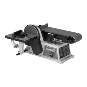
4" Belt / 6" Disc Sander
(Model SM500)
PART NO. 491836-00 REV. 1 05-18-06
Copyright © 2006 Delta Machinery
To learn more about DELTA MACHINERY
ESPAÑOL: PÁGINA 23
visit our website at: www.deltamachinery.com.
FRANÇAIS: PAGE 45
For Parts, Service, Warranty or other Assistance,
1-800-223-7278 (
1-800-463-3582).
please call
In Canada call
Advertisement
Table of Contents

Related Manuals for Delta ShopMaster 491836-00


Summary of Contents for Delta ShopMaster 491836-00
- Page 1 4" Belt / 6" Disc Sander (Model SM500) PART NO. 491836-00 REV. 1 05-18-06 Copyright © 2006 Delta Machinery To learn more about DELTA MACHINERY ESPAÑOL: PÁGINA 23 visit our website at: www.deltamachinery.com. FRANÇAIS: PAGE 45 For Parts, Service, Warranty or other Assistance, 1-800-223-7278 ( 1-800-463-3582).
-
Page 2: Table Of Contents
NOT be modified and/or used for any application other than for which it was designed. If you have any questions relative to its application DO NOT use the product until you have written Delta Machinery and we have advised you. -
Page 3: Safety Guidelines - Definitions
• All toys, washable furniture and utensils used by children should be washed thoroughly before being used again. FIRE HAZARD collected sanding dust from sanding surface coatings (polyurethane, linseed oil, etc.) can self-ignite in dust collector bag or elsewhere and cause fire. To reduce risk, empty bag frequently and strictly follow sander manual and coating manufacturer's instructions. -
Page 4: Important Safety Instructions
Damage to the machine and/or injury may result. 13. USE RECOMMENDED ACCESSORIES. The use of accessories and attachments not recommended by Delta may cause damage to the machine or injury to the user. 14. USE THE PROPER EXTENSION CORD. Make sure IMPORTANT SAFETY INSTRUCTIONS your extension cord is in good condition. -
Page 5: Additional Specific Safety Rules
ADDITIONAL SPECIFIC SAFETY RULES READ AND UNDERSTAND ALL INSTRUCTIONS. FAILURE TO FOLLOW THESE INSTRUCTIONS MAY RESULT IN ELECTRICAL SHOCK, FIRE AND / OR DO NOT OPERATE THIS MACHINE until it is completely assembled and installed according to the instructions. A machine incorrectly assembled can cause serious injury. -
Page 6: Grounding Instructions
POWER CONNECTIONS A separate electrical circuit should be used for your machines. This circuit should not be less than #12 wire and should be protected with a 20 Amp time lag fuse. If an extension cord is used, use only 3-wire extension cords which have 3- prong grounding type plugs and matching receptacle which will accept the machine’s plug. -
Page 7: Extension Cords
F O R E W O R D The ShopMaster Model SM500 is a 4" Belt, 6" Disc Sander that comes equipped with a 5.2 AMP 120 Volt Single Phase Induction Motor, a tilting table, a miter gauge, a backstop, a 4" x 36" 60-grit sanding belt, and a 6" 60-grit sanding disc. -
Page 8: Carton Contents
1. Motor and Base 2. Disc Table 3. Belt and Pulley Guard 4. Disc Plate 5. Dust Chute 6. Support Rod 7. Lower Disc Guard 8. Sanding Disc 9. Backstop 10. Miter Gauge U N PACKING AND CLEANING Carefully unpack the machine and all loose items from the shipping container(s). Remove the protective coating from all unpainted surfaces. -
Page 9: Assembly
6 mm Hex Wrench (Supplied) ADJUSTING THE BELT TENSION Your sander was shipped from the factory with the drive belt (A) Fig. 1 attached to both pulleys (B) and (C). Before assembling the machine, check and adjust the belt tension. - Page 10 ATTACHING THE BELT AND PULLEY GUARD Attach the belt and pulley guard (A) Fig. 4 to the machine base using the two M6x1x30mm cheese head screws (B). INSTALLING THE SANDING DISC PLATE 1. Turn the 1/4-20 x 1/4" hex socket set screw (A) Fig. 5 counter-clockwise until it clears the hole (B) in the sanding plate.
- Page 11 INSTALLING THE DISC SANDER TABLE 1. Thread an M8 x 1.25 x 20mm hex socket head screw (A) Fig. 10 partially into the hole in the base of the sander. Insert the rod (B) into the hole. Align the flat of the rod (B) with the screw (A). Tighten the screw (A).
- Page 12 Insert the pan head screw (B) Fig.12 through the hole in the dust spout and thread it into the taped hole in the sander base. Repeat this process for the two remaining holes.
-
Page 13: Operation
3. Alternately, you can secure the sander by fastening it to a mounting board 18" x 24" or larger. The diagram in Fig. 16 shows the size and center-to-center distance of the holes that you will need to drill in the mounting board. - Page 14 LOCKING THE SWITCH IN THE “OFF” POSITION IMPORTANT: When the tool is not in use, the switch should be locked in the “OFF” position to prevent unauthorized use. To lock the machine, grasp the switch toggle (A) and pull it out of the switch (Fig. 19). With the switch toggle (A) removed, the switch will not operate.
-
Page 15: Tilting The Table
ADJUSTING THE BACKSTOP SQUARE WITH THE SANDING BELT DISCONNECT MACHINE FROM POWER SOURCE. 1. Before adjusting, move the belt tension lever (A) Fig. 23 all the way to the left to the "TIGHTEN" position. 2. Place a square (B) Fig. 24 on the sanding belt with one end of the square against the backstop. See if the backstop is square with the sanding belt. -
Page 16: Miter Gauge
ADJUSTING THE MITER GAUGE SLOT PARALLEL WITH THE SANDING DISC DISCONNECT MACHINE FROM POWER SOURCE. 1. Place an adjustable combination square on the table with the part (A) Fig. 27 in the miter gauge slot (B) to check the distance from the slot to the sanding disc. Check the other side of the disc in the same manner (Fig. 28). The distances should be the same. -
Page 17: Wrench Storage
(A) Fig. 32 should be positioned a maximum of 1/16" away from the sanding belt (B). WRENCH STORAGE Two holes are provided in the base casting to store the two wrenches (A) Fig. 33, supplied with the sander. Fig. 31 Fig. 32... -
Page 18: Replacing The Sanding Disc
4. Apply belt tension by sliding the tension lever (C) Fig. 35 to the left. 5. Replace the backstop that was removed in STEP 2. 6. Connect the power source to the sander. Check the belt tracking. (Refer to the section "TRACKING THE SANDING BELT"). - Page 19 M A C H I N E U S E SURFACING OR EDGE SANDING WITH THE SANDING BELT Always use the backstop (A) Figs. 39 and 40 when surface-sanding (Fig. 39) or when edge sanding Fig. 40. Hold the workpiece firmly and keep your fingers away from the sanding belt. Keep the end of the workpiece against the backstop and move the workpiece evenly across the sanding belt.
-
Page 20: Failure To Sta Rt
For assistance with your machine, visit our website at www.deltamachinery.com for a list of service centers or call the DELTA Machinery help line at 1-800-223-7278 (In Canada call 1-800-463-3582). Fig. 44... -
Page 21: Keep Machine Clean
Apply household floor paste wax to the extension table or other work surface weekly. PARTS, SERVICE OR WARRANTY ASSISTANCE All Delta Machines and accessories are manufactured to high quality standards and are serviced by a network · of Porter-Cable Delta Factory Service Centers and Delta Authorized Service Stations. To obtain additional information regarding your Delta quality product or to obtain parts, service, warranty assistance, or the location of the nearest service outlet, please call 1-800-223-7278 (In Canada call 1-800-463-3582). -
Page 22: Warranty
180 days. Delta may re q u i re that electric motors be re t u rned prepaid to a motor m a n u f a c t u re r ’s authorized station for inspection and repair or replacement. Delta will not be responsible for any asserted defect which has resulted from normal wear, misuse, abuse or repair or alteration made or specifically authorized by anyone other than an authorized Delta service facility or re p resentative. - Page 23 Para obtener más información sobre Delta Machinery, visite nuestro sitio web en: www.deltamachinery.com Para las piezas, el servicio, la garantía o la otra ayuda 1-800-223-7278 ( llaman por favor Lijadora de Correa de 4" / Disco de 6 (Modelo SM500)
-
Page 24: Instrucciones De Seguridad Importantes
Si usted tiene cualquiera pregunta el pariente a su aplicación no utiliza el producto hasta que usted haya escrito Delta Machinery y nosotros lo hemos aconsejado. -
Page 25: Seguridad Personal
PAUTAS DE SEGURIDAD/DEFINICIONES Es importante para usted leer y entender este manual. La información que lo contiene relaciona a proteger SU SEGURIDAD y PREVENIR los PROBLEMAS. Los símbolos debajo de son utilizados para ayudarlo a reconocer esta información. Indica una situación de inminente riesgo, la cual, si no es evitada, causará la muerte o lesiones serias. Indica una situación potencialmente riesgosa, que si no es evitada, podría resultar en la muerte o lesiones s e r i a s . -
Page 26: Normas Generales De Seguridad
El resultado podría ser daños a la máquina y/o lesiones. 13. UTILICE ACCESORIOS RECOMENDADOS. La utilización de accesorios y aditamentos no recomendados por Delta podría causar daños a la máquina o lesiones al usuario. 14. UTILICE EL CORDÓN DE EXTENSIÓN ADECUADO. - Page 27 NORMAS ESPECÍFICAS ADICIONALES DE SEGURIDAD ES IMPORTANTE PARA USTED LEER Y ENTENDER ESTE MANUAL. EL INCUMPLIMIENTO DE LAS INSTRUCCIONES ENUMERADAS DEBAJO PUEDE PROVOCAR DESCARGA ELÉCTRICA, NO UTILICE ESTA MÁQUINA hasta que esté completamente montada e instalada de acuerdo con las instrucciones. Una máquina montada incorrecta- mente puede causar lesiones graves.
-
Page 28: Instrucciones De Conexión A Tierra
CONEXIONES A LA FUENTE DE ALIMENTACIÓN Debe utilizarse un circuito eléctrico independiente para las máquinas. Este circuito debe tener alambre de no menos del No. 12 y debe estar protegido con un fusible de acción retardada de 20 A. Si se utiliza un cordón de extensión, utilice únicamente cordones de extensión de tres alambres que tengan enchufes de tipo de conexión a tierra con tres terminales y un receptáculo coincidente que acepte el enchufe de la máquina. -
Page 29: Cordones De Extensión
P R O L O G O El modelo SM500 del delta es 4 " correa; 6 " lijadora del disco y viene equipado de; 5.2 AMP motor de inducción la monofásico del hp 120Volt, inclinando el vector, ingletes galga, tope, 4 " x 36 " 60 cierra fuertemente la correa que enarena y 6 " 60 cierran fuertemente el disco que enarena. - Page 30 CONTENIDO DE CART O N El motor y se Basa La Mesa del disco El cinturón y la Polea Protegen El Plato del disco Quite el polvo Tobogán Sostenga la Barra El Guardia más bajo del Disco El Disco de Sanding La mampara 10.
- Page 31 Para su pr opia seguridad, no conecte la lijadora a la fuente de energia hasta que la maquina haya sido ensamblada por completo y uste HERRAMIENTAS DE ENSAMBLAJE REQUERIDAS 1/8" Llave Inglesa Hexagonal (suministró) 6 Mm Llave Inglesa Hexagonal (suministró) ESTIMACIÓN DEL TIEMPO DE ENSAMBLAJE AJUSTANDO LA TENSION DE CORREA Su lijadora se envía de fábrica con la correa de marcha (A) Fig.
- Page 32 ENSAMBLAJE DEL PROTECTOR DE CORREA Y POLEA Ensamble el protector de correa y polea (A) Fig. 4 a la base de la máquina haciendo uso de los dos tornillos de 30 mm (1-3/16 pulg.) de largo (B). ENSAMBLAJE DEL PLATO DEL DISCO DE LIJADO Enrosque el tornillo de fijación de 1/4 pulg.
- Page 33 ENSAMBLAJE DEL DISCO DE LIJADO 1. Asegúrese que el plato del disco de lijado (A) Fig. 8 esté limpio. 2. Quite el respaldo del disco de lijado, y oprima el disco (B) firmemente en su sitio completamente a l rededor del plato de lijado, como puede apreciarse en la Fig.
- Page 34 ENSAMBLAJE DEL CONDUCTO DE POLVO Alinee los tres hoyos en el tobogán (A) Fig. 12 de polvo con los tres hoyos en el lado izquierdo de la base de sanding. Introduzca el tornillo de cabeza troncocónica (B) Fig. 12 a través del orificio en el tubo de descarga de polvo y enrósquelo en el orificio roscado en la base de la lijadora.
-
Page 35: Operación
3. Una alternativa para afianzar la lijadora a la superficie de apoyo es la de afianzar la base de la lijadora a una tabla de montaje con tamaño mínimo de 18 x 24 pulgadas. El diagrama que aparece en la Fig. - Page 36 FIJANDO EL INTERRUPTOR EN LA POSICION DE APAGADO IMPORTANTE: Cuándo la herramienta no es adentro uso, el interruptor se debe bloquear en el OFF posición para prevenir uso desautorizado. E s t o puede hacerse tomando la pieza acodada (A) y removiéndolo por completo del interruptor, tal como se ilustra en la Fig.
- Page 37 AJUSTANDO EL ENCUADRE DEL CONTRATOPE CON LA CORREA DE LIJADO Desconecte la máquina de la fuente de potencia! 1. Cuando vaya a realizar dicho ajuste, asegúrese que la palanca de tensionamiento de correa (A) Fig. 23 esté completamente hacia el lado izquierdo en la posición apretada, 2.
- Page 38 AJUSTANDO LA RANURA DE LA ESCUADRA DE INGLETES DE MANERA PARA- LELA AL DISCO DE LIJADO Desconecte la máquina de la fuente de potencia! 1. Coloque y el cuadrado ajustable de la combinación sobre la mesa con la parte (A) Fig. 27 en la ranura (B) del calibrador de mitra para verificar la distancia de la ranura al disco del sanding.
- Page 39 UTILIZANDO EL CONJUNTO DE MESA CON LA CORREA DE LIJADO Cuando se utiliza el brazo de lijado (A) Fig. 31 en la posición vertical, se puede mover el conjunto de mesa completo (B) desde la unidad de disco a la unidad de correa. Desconecte la máquina de la fuente de potencia! 1.
- Page 40 REEMPLAZO DE LA CORREA DE LIJADO Desconecte la máquina de la fuente de potencia! 1. Quite el tornillo (A) Fig. 34 y quite el contratope (B). 2. Deslice la palanca de tensionamiento (C) Fig. 35 a la derecha para soltar la tensión de la correa de lijado, y quite la correa de lijado (D) de ambos tambores de lijado, como se ilustra aquí.
- Page 41 UTILIZAR LA MAQUINA LIJADO DE SUPERFICIE O DE BORDE CON LA CORREA DE LIJADO Siempre utilice la mampara (A) Figs. 39 y 40 cuando de superficie-sanding (Fig. 39) o cuando sanding de orilla (Fig. 40). Tenga el workpiece firmemente y mantenga los dedos lejos del correa de lijado. Mantenga el fin del material contra el contratope y mueva el material uniformemente a través del correa de lijado.
-
Page 42: Localizacion De Fa L L A S
También, vea si hay fusibles fundidos o ruptores abiertos en el circuito. Para obtener asistencia para su máquina, visite nuestro sitio Web en www.deltamachinery.com para tener acceso a una lista de centros de servicio o llame a la línea de ayuda de Delta Machinery al 1-800-223-7278. (En Canadá, llame al 1-800- 463-3582.) -
Page 43: Mantenimiento
P a r a l a o p e r a c i ó n m á s s e g u r a, solamente el delta recomendó los accesorios se debe utilizar con este producto. - Page 44 Delta que durante el uso normal haya presentado defectos de fabricación o de material, s i e m p re que el cliente devuelva el producto con el transporte prepagado a un centro de servicio de fábrica Delta o una estación de servicio autorizado Delta, con un comprobante de compra del producto, dentro del plazo de dos años y dé...
- Page 45 152 mm (6 po) (modèle SM500) 491836-00 REV. 1 05-18-06 Copyright © 2006 Delta Machinery Pour en savoir plus à propos de DELTA MACHINERY consulter le site Web au : www.deltamachinery.com. Pour des pièces, réparations, garantie ou toute autre demande d’aide 1-800-223-7278 1-800-463-3582).
-
Page 46: Directives De Sécurité Importantes
Delta Machinery recommande fortement de NE PAS modifier ce produit ou de NE PAS l’utiliser pour une application autre que celle pour laquelle il a été conçu. Si vous avez des questions à propos de son utilisation, N’utilisez PAS le produit avant de communiquer avec Delta Machinery et d’obtenir nos conseils. -
Page 47: Proposition 65 De La Californie
LIGNES DIRECTRICES EN MATIÈRE DE SÉCURITÉ — Il est important que vous lisiez et compreniez ce mode d’emploi. Les informations qu’il contient concernent VOTRE SÉCURITÉ et visent à ÉVITER TOUT PROBLÈME. Les symboles ci-dessous servent à vous aider à reconnaître cette information. Indique une situation dangereuse imminente qui, si elle n’est pas évitée, causera la mort ou des graves b l e s s u r e s . -
Page 48: Règles Générales De Sécurité
1 3 . UTILISER LES ACCESSOIRES RECOMMANDÉS. L’utilisation d’accessoires qui n’ont pas été recommandés par Delta est susceptible d’endommager la machine ou de blesser l'utilisateur. DIRECTIVES DE SÉCURITÉ IMPORTANTES 1 4 . UTILISER LA RALLONGE ÉLECTRIQUE A P P R O P R I É E . - Page 49 RÈGLES DE SÉCURITÉ SPÉCIFIQUES SUPPLÉMENTAIRES LIRE ATTENTIVEMENT TOUTES LES MISES EN GARDE ET DIRECTIVES D’UTILISATION AVANT D’UTILISER CET ÉQUIPEMENT. À défaut de suivre les directives sous mentionnées, un choc électrique, un incendie, des dommages ou une blessure corporelle grave pourraient survenir. NE PAS FAIRE FONCTIONNER CETTE MACHINE avant qu’elle ne soit entièrement assemblée et installée conformément à...
-
Page 50: Connexions Électriques
CONNEXIONS ÉLECTRIQUES Un circuit électrique séparé doit être utilisé pour vos machines. Ce circuit doit utiliser un câble de calibre 12 au minimum et doit être protégé par un fusible temporisé de 20 A. Si vous utilisez une rallonge électrique, n’utiliser que des rallonges à... -
Page 51: Rallonges Électriques
RALLONGES ÉLECTRIQUES Utiliser les rallonges électriques appropriées S’assurer que la rallonge est en bon état et qu’il s’agit d’une rallonge à 3 fils avec une fiche de mise à la terre à 3 lames et prise de courant compatible avec la fiche de la machine. -
Page 52: Contenu Du Carton
1. Moteur et base 2. Table du disque 3. Dispositif de protection pour la courroie et la poulie 4. Plaque du disque 5. Sortie de poussière 6. Tige de support 7. Dispositif inférieur de protection du disque 8. Disque abrasif 9. - Page 53 Pour sa pro p re sécurité, ne pas brancher la machine à une source d’alimentation jusqu’à ce que la machine soit entièrement assemblée, ni avant d'avoir lu et compris l’intégralité de ce mode d ' e m p l o i . OUTILS NÉCESSAIRES POUR L’...
- Page 54 INSTALLATION DU DISPOSITIF DE PROTECTION DE LA COURROIE ET DE LA POULIE Assembler le dispositif de protection de la courroie et de la poulie (A, fig. 4) à la base de la machine à l'aide des deux vis à tête cylindrique bombée (B) M6x1x30 mm. INSTALLATION DE LA PLAQUE SUPPORT D'ABRASIF 1.
- Page 55 INSTALLATION DU DISQUE ABRASIF 1. Nettoyer la plaque support d'abrasif (A, fig. 8. 2. Décoller la pellicule au dos du disque abrasif et appliquer le disque (B) fermement en place sur toute la surface de la plaque de ponçage (fig. 8). ASSEMBLAGE DU COUVERCLE INFÉRIEUR AU DISQUE ABRASIF Fixer le couvercle inférieur (A, fig.9) sur le dispositif de protection de la courroie et de la poulie à...
- Page 56 ASSEMBLAGE DE LA SORTIE DE POUSSIÈRE Aligner les trois trous de la sortie de poussière (A, fig. 12) avec les trois trous du côté gauche de la base de la ponceuse. Insérer la vis à tête cylindrique à dépouille (B) fig.
- Page 57 3. Alternativement, fixer la ponceuse à une planche de montage 18 x 24 po (46 x 61 cm) ou de plus grande dimension. Le schéma de la figure 16 illustre la dimension et la distance centre à centre des trous à percer dans la planche de montage.
- Page 58 VERROUILLAGE DE L'INTERRUPTEUR EN POSITION D'ARRÊT I M P O R TANT lorsque l’outil l’interrupteur doit être verrouillé en position d’arrêt afin d’empêcher toute utilisation non autorisée. Pour verrouiller l’outil, saisir la bascule de l’interrupteur (a) et la retirer de l’interrupteur (fig. 19). Une fois la bascule de l’interrupteur (a) retirée, l’interrupteur ne fonctionnera pas.
-
Page 59: Inclinaison De La Table
RÉGLAGE DE LA BUTÉE ANTIRETOUR D'ÉQUERRE AVEC LA BANDE ABRASIVE DÉBRANCHER LA MACHINE DE LA SOURCE D’ALIMENTAT I O N . 1. Avant le réglage, déplacer le levier (A, fig. 23) de tension de la courroie complètement à gauche en position « SERRÉE ». - Page 60 RÉGLAGE DE LA FENTE DE LA JAUGE À ONGLET PARALLÈLE AU DISQUE ABRASIF DÉBRANCHER LA MACHINE DE LA SOURCE D’ALIMENTAT I O N 1. Placer une équerre combinée ajustable sur la table avec une partie (A, fig. 27) dans la fente de la jauge à onglet (B) pour vérifier la distance entre la fente et le disque abrasif.
- Page 61 LA PONCEUSE Lors de l'utilisation du bras de la ponceuse (A, fig. 31) dans la position verticale, il est possible de déplacer entièrement le module de l'appareil à disque à celui à courroie. DÉBRANCHER LA MACHINE DE LA SOURCE D’ALIMENTAT I O N . 1.
- Page 62 REMPLACEMENT DE LA BANDE ABRASIVE DÉBRANCHER LA MACHINE DE LA SOURCE D’ALIMENTAT I O N 1. Desserrer la vis (A, fig. 34) et déposer la butée antiretour (B). 2. Glisser le levier de tension (C, fig.35) vers la droite pour réduire la tension de la bande abrasive. Retirer la bande abrasive (D) des deux cylindres de contact.
-
Page 63: Utilisation De La Machine
U T I L I S ATION DE LA MACHINE SURFAÇAGE OU PONÇAGE DE BORD À L'AIDE DE LA BANDE ABRASIVE Toujours utiliser la butée antiretour (A, figures 39 et 40) lors de surfaçage (fig. 39) ou de ponçage de bord (fig. 40). 40. Tenir la pièce solidement et éloigner les doigts de la bande abrasive. - Page 64 PONÇAGE D'EXTRÉMITÉ AVEC LA COURROIE Lors du ponçage des extrémités de grandes pièces, utiliser la bande abrasive avec le bras de la ponceuse en position verticale et le module de la table déplacé par rapport à la courroie (fig. 43). Consulter les sections« MODIFICATION DE LA POSITION DU BRAS DE LA PONCEUSE »...
- Page 65 PIÈCES RÉPARATION OU AIDE À PROPOS DE Tous les outils et accessoires Delta sont fabriqués selon des normes de qualité élevées et sont réparés par un réseau de centres de réparation de l’usine Porter-Cable — Delta et de centres de réparation agréés Delta. Pour de plus amples renseignements à...
-
Page 66: Garantie
à Delta une opportunité raisonnable de vérifier le défaut présumé par une inspection. La période de garantie des produits Delta réusinés est de 180 jours. Delta peut demander que les moteurs électriques soient re t o u rn é s (transport payé... - Page 67 Delta pour obtenir toutes pièces ou accessoires pour tous produits Porter-Cable Delta. Si aucun n’est disponible, composer le 8 0 0 - 2 2 3 - 7 2 7 8 et vous serez redirigés vers le centre de réparation de l'usine Porter-Cable Delta le plus près de chez vous.
Need help?
Do you have a question about the ShopMaster 491836-00 and is the answer not in the manual?
Questions and answers