Asus ROG Strix G15CE Manual
- Quick start manual (112 pages) ,
- Quick start manual (112 pages) ,
- Service manual (26 pages)
Advertisement
- 1 ASUS Desktop ROG Strix G15CE Overview
- 2 Components Top View
- 3 Components Bottom View
- 4 Appropriate Tools
- 5 SLIDE DOOR
- 6 VGA CARD
- 7 DDR & SSD CARD
- 8 FAN
- 9 MAIN BOARD with CPU COOLER & CPU
- 10 FRONT BEZEL and LED BOARD
- 11 POWER SWITCH
- 12 FRONT BEZEL ASSY
- 13 TOP COVER
- 14 FRONT IO BOARD
- 15 HDD
- 16 POWER SUPPLY
- 17 LED BOARD
- 18 CABLE ASSEMBLY
- 19 Documents / Resources
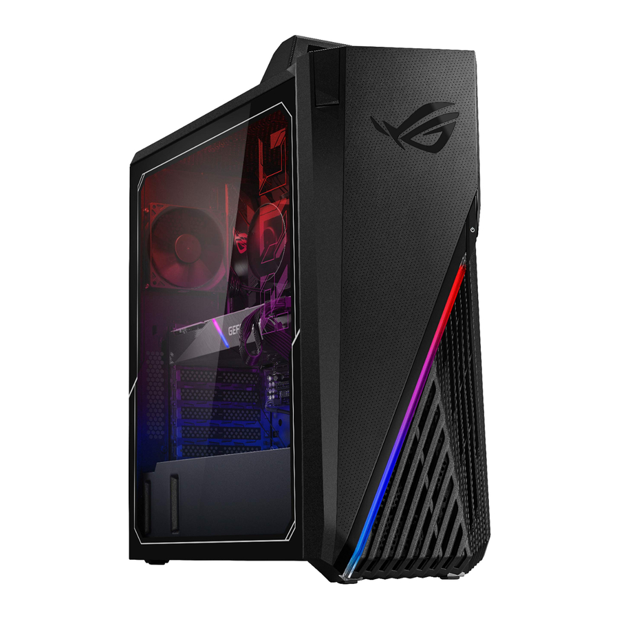
ASUS Desktop ROG Strix G15CE Overview
Front & Top View

- Power button
- Headphone port
- Microphone port
- USB 3.2 Gen 1 Type-C® port
- USB 3.2 Gen 1 port
- Headset hanger
Rear Panel View

- DisplayPort
- HDMI™ port.
- USB port with BIOS FlashBack™
- BIOS FlashBack™ button
- USB 2.0 ports
- USB 3.2 Gen 2 ports
- USB 3.2 Gen 2x2 Type-C® port
- Audio USB Type-C® port
- Rear Speaker Out port (Black)
- Center/Subwoofer port (Orange)
- Microphone port (Pink)
- Line In port (Lime)
- Line Out port (Light blue)
- Power connector
- Expansion slot brackets
- ASUS Graphics Cards (On selected models only)
- Intel Wi-Fi 6 ports
- LAN (RJ-45) port
- Air vents
Components Top View


Components Bottom View

Appropriate Tools
Please prepare and select the appropriate tools to disassemble/assemble for the ROG Strix (G15CE) desktop.
- Screwdriver
Please accord to different screw specification to choose different screwdriver and head.
![]()
- Plastic Blade
![]()
- Plastic Tweezers
Use a pair of tweezers to remove/insert/tidy cables.
![]()
- Thickness Gauge
Thickness compass specification 0.05mm-1.5mm. Use it to measure the gap.
![]()
- Magnetism Board
Suggest local buy magnetism board to place screw, avoid mix different type screw to cause assembly damage.
![]()


- Alcohol 95%
![]()
- Thermal Grease
![]()
- Cable Tie (Local Buy)
![]()
- Needle nose pliers
![]()
- Glove
![]()
- Dust-free Cloth
![]()


SLIDE DOOR
Disassembly Notice
Please be sure to pull out adapter and disconnect the battery.
| Screws | QTY | Spec | Torque (kgf-cm) |
 | 4 | SCREW #6-32 L6*H2.3 (B)B-NI-ZN | 8.0± 0.5 |
- Remove screws *4pcs.
![]()
- Pull out the side doors*2pcs.


VGA CARD
Disassembly Notice
Please be sure to pull out adapter and disconnect the battery.
| Screws | QTY | Spec | Torque(kgf-cm) |
 | 2 | SCREW #6-32*L6 (B)B-NI-ZN NY | 4.0± 0.5 |
 | 2 | SCREW M2.5*4L(4.5,1.8) (P) #1 | 4.0± 0.5 |
 | 2 | SCREW M3*6L (5.5,2.15) (P) #2 | 4.0± 0.5 |

- Disconnect cables (Yellow mark).
- Remove screws *4pcs (Red and Blue mark).
- Press and unlock the VGA card.
- Take out the VGA card.
![]()
- Remove screws *2pcs, and take TUF SUP BKT


DDR & SSD CARD
Disassembly Notice
Please be sure to pull out adapter and disconnect the battery.
| Screws | QTY | Spec | Torque (kgf-cm) |
 | 2 | Retention Screw | 2.0 ± 0.2 |

- Unlock and then remove DDR *4pcs.
- Remove screw *2pcs, and then take out the SSD Housing.
- Unlock and remove SSD *1pcs.


Assembly Notice
 Please follow the below criteria to assemble DDR.

| Memory slot | 1pcs | 2pcs | 3pcs | 4pcs |
| DIMM_A1 | ● | ● | ||
| DIMM_A2 | ● | ● | ● | ● |
| DIMM_B1 | ● | |||
| DIMM_B2 | ● | ● | ● |
FAN
Disassembly Notice
Please be sure to pull out adapter and disconnect the battery.
| Screws | QTY | Spec | Torque (kgf-cm) |
 | 4 | M5*10L (F) W-NI (TP5) | 8.0± 0.5 |
- Release CONDUCTIVE Cloth (Green mark)*1pcs and disconnect (yellow mark) FAN connector *1pcs.
![]()
- Remove 4 screws on the outside of iron grid.
![]()
- Take out the Fan*1 pcs.
![]()


MAIN BOARD with CPU COOLER & CPU
Disassembly Notice
Please be sure to pull out adapter and disconnect the battery.
| Screws | QTY | Spec | Torque (kgf-cm) |
 | 2 | M3*4L (6.3,2.05) (P) #2 | 6.0± 0.5 |
 | 6 | SCREW #6-32 L6*H2.3 (B) W-NI | 8.0± 0.5 |
 | 4 | Retention Screw | 8.0± 0.5 |
- Disconnect (Yellow mark) connectors *7pcs.
![]()
- Remove screws *8pcs (Red and green mark).
- Take out the Main Board.
![]()
- Unscrew 4pcs screws and remove the CPU Cooler.

- Remove the CPU.


CPU COOLER Disassembly Notice
If the CPU COOLER is hard to disassemble, please move the COOLER left and right to separate

Pin facing down on Processor packaging to protect the CPU.

Assembly Notice
Please follow the instructions to assemble the CPU.

Assembly Notice
Please be sure to pull out adapter and disconnect the battery.
Please make sure that re-smear thermal material on CPU Die, if thermal module have to be reassembled.
- Using dust-free cloth with 95% alcohol to clean up the residual thermal grease on CPU& GPU Die.

- Please use plastic tool (Plastic stick) to get Thermal Grease, and smear over CPU around 0.2~0.3mm thick.


 Attention:
- Please clean plastic tool with Dust-free cloth and 95% alcohol before using.
- Please mix well before Thermal grease using (In case Oil-Grease separation).
FRONT BEZEL and LED BOARD
Disassembly Notice
Please be sure to pull out adapter and disconnect the battery.
| Screws | QTY | Spec | Torque (kgf-cm) |
 | 2 | M2.5*5L (4.6,1.7) (P) #1 | 3.0± 0.5 |
 | 3 | M2.5*4.2L(7.3,2.3) (P)+W | 4.0± 0.5 |
- Pull the latch slightly away.

- Disconnect the connectors *3pcs of the cable inside.
![]()
- Turn over the front case and Remove screws *2pcs.
![]()
- Tear the FRONT LENS FOIL slightly ( Yellow mark).
- Remove screws *3pcs located on the LED CR board.
![]()
- Take out the LED CR BD *1pcs.
![]()


POWER SWITCH
Disassembly Notice
Please be sure to pull out AC POWER CORD.
- Remove POWER SWITCH HOLDER with POWER SW CABLE from the front case.

- Release hooks (green mark) then take out POWER SW CABLE from POWER SWITCH HOLDER.


Assembly Notice
Please follow the steps below to assemble POWER SWITCH HOLDER and POWER SW CABLE.


*When inserting the switch cable into the holder, please make sure the hooks no broken or deformation.
*After finishing the assembly process, press the power button to ensure the power button function is OK. (It has a click feeling is OK)
FRONT BEZEL ASSY
FRONT BEZEL Assembly Notice
NOTE! Before assembling the FRONT BEZEL ASSY, please carefully read the following assembly instructions.
When assembling the LED board, USB cable and power cord on the FRONT BEZEL ASSY, please make sure that the USB cable and power cord do not touch the PIN HEADER of the LED board, otherwise it may cause a short circuit and overheating. Please follow the steps below to confirm and assemble the power cord, USB cable, LED board.
- Please use ACETATE TAPE to wrap one end of the POWER Cable and USB Cable.

- Paste PINHEADER ACETATE FABRIC *3pcs to cover some of the pin headers on the LED control board.

- After connecting the POWER and USB cable to the LED board, please tidy up the cables in the direction of the yellow arrow and be careful to avoid the PIN HEADER (marked in red).

- Check that the cable direction must follow the yellow arrow, paste tape to fix then reassemble the FRONT BEZEL ASSY.


TOP COVER
Disassembly Notice
Please be sure to pull out adapter and disconnect the battery.
| Screws | QTY | Spec | Torque (kgf-cm) |
 | 2 | SCREW M2.5*6L (5.5,0.8) (K) #1//KL,MACHINE NY B-ZN | 3.0± 0.5 |
- Use the Plastic Blade to Remove the Handle Cover.

- Remove screws *2pcs located on the end of the Handle.

- Pull the latch slightly away from the edge case until it's detached.

- Take out the Top Case.
![]()


FRONT IO BOARD
Disassembly Notice
Please be sure to pull out adapter and disconnect the battery.
| Screws | QTY | Spec | Torque (kgf-cm) |
 | 2 | M2.5*4L (K) B-ZN NY #1 | 3.0± 0.3 |
 | 2 | M3*4L (6.3,2.05) (P) | 6.0± 0.5 |
- Remove screws *2pcs.
![]()
- Disconnect cables *2pcs.
![]()
- Remove screws *2pcs.

- Separate FRONT IO BOARD and FIO bracket.


Assembly Notice
When assemble FIO USB cable on FRONT IO BOARD, please follow below steps to paste USB CABLE ACETATE TAPE.
- Taking the ACETATE TAPE to align the centerline and parallel to the IO BOARD.
![]()
- Winding it parallel.
![]()
- Attach fully then done.
![]()


HDD
Disassembly Notice
Please be sure to pull out adapter and disconnect the battery.
| Screws | QTY | Spec | Torque (kgf-cm) |
 | 4 | SCREW #6-32*6L(7.1,2.3) (B) #2 | 6.5± 0.5 |
- Remove screws *4pcs.
![]()
- Disconnect the cables *2pcs
![]()
- Take the HDD out.
![]()


POWER SUPPLY
Disassembly Notice
Please be sure to pull out adapter and disconnect the battery.
| Screws | QTY | Spec | Torque (kgf-cm) |
 | 4 | SCREW #6-32*L6 (B)B-NI-ZN NY | 8.0± 0.5 |
- Disconnect the cables *4pcs.
![]()
- Remove screws *4pcs.

- Take out the POWER SUPPLY.


LED BOARD
Disassembly Notice
Please be sure to pull out adapter and disconnect the battery.
| Screws | QTY | Spec | Torque (kgf-cm) |
 | 3 | SCREW M2.5*4L (K) B-ZN NY | 2.5± 0.2 |
 | 2 | SCREW M2.5*4L (K) B-ZN NY | 2.5± 0.2 |

- Remove screw*3pcs, and then disconnect cable *1pcs.
- Remove screw*2pcs, and then disconnect cable *1pcs.
CABLE ASSEMBLY
Assembly Notice
Please be sure to pull out adapter and disconnect the battery.
Tidy up the cable of the back mainframe as illustrated.

SERVICE AND SUPPORT
Visit our multi-language website at https://www.asus.com/support/
Safety precautions
- Before handling components, use a grounded wrist strap or touch a safely grounded object to avoid damaging them due to static electricity.
- Keep liquids or moisture away from your Notebook PC to avoid short circuits.
- Remove rings, watches, and any other metal objects from your hands.
- Hold components by the edges to avoid touching the ICs.
- Properly install all components before connecting the AC power. Do not use power adapters or batteries from other devices to reduce the risk of injury to persons due to fire or explosion. Use only certified power adapters or batteries supplied by the manufacturer or authorized retailers.
- Detach all clips or flaps before removing cables to prevent damage.
- Disconnect cables, connectors, and power plugs by pulling the plug evenly to avoid damage.
- Use the correct screw models on your Notebook PC to prevent damage.
- Confirm that the cable orientation is correct before connecting any cables.
- Fully remove all adhesive residue after removing and before installing any components.
- Photograph the appearance of cables, cable routing, connectors, and screws for later reference before proceeding with each step.
Documents / Resources
References
Download manual
Here you can download full pdf version of manual, it may contain additional safety instructions, warranty information, FCC rules, etc.
Advertisement


Need help?
Do you have a question about the ROG Strix and is the answer not in the manual?
Questions and answers