Table of Contents
Advertisement
Advertisement
Table of Contents

Related Manuals for Asus ROG GR8


Summary of Contents for Asus ROG GR8
- Page 1 REPUBLIC OF GAMERS ROG GR8 User Guide...
- Page 2 ASUS will only be responsible for or indemnify you for loss, damages or claims based in contract, tort or infringement under this Warranty Statement. This limit also applies to ASUS’ suppliers and its reseller. It is the maximum for which ASUS, its suppliers, and your reseller are collectively responsible.
-
Page 3: Table Of Contents
Resetting your PC ...................25 Recovering from a system image file ............26 Removing everything and reinstalling Windows ........27 Turning off your ROG GR8 ................28 Putting your ROG GR8 to sleep ..............28 Entering the BIOS Setup ................28 Quickly enter the BIOS ..................29 ROG GR8... - Page 4 Contents Upgrading your ROG GR8 Upgrading memory modules ..............32 Installing a 2.5-inch storage drive ..............37 Appendix Safety information ...................44 Setting up your system.................44 Care during use ....................44 Regulatory notices ...................46 ASUS contact information ................52 ROG GR8...
-
Page 5: About This Manual
PC, organized through the following chapters: Chapter 1: Getting to know your ROG GR8 This chapter details the hardware components of your ROG GR8. Chapter 2: Using your ROG GR8 This chapter provides you with information on using your ROG GR8. -
Page 6: Package Contents
NOTE: Actual product specifications and package contents may vary depending on your country or region. IMPORTANT! Bring the warranty card to the ASUS Service Center for replacement of the defective components if the device or its components fail or malfunction during normal and proper use within the warranty period. -
Page 7: Getting To Know Your Rog Gr8
Getting to know your ROG GR8... -
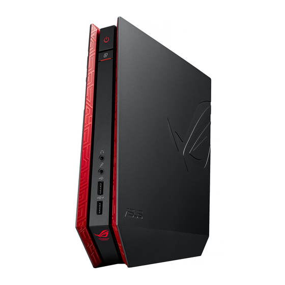
Page 8: Features
Features Front panel ROG GR8... - Page 9 Power button The power button allows you to turn the ROG GR8 on or off. Miracast Receiver button The Miracast Receiver button allows you to mirror the display from other Miracast-enabled devices. Headphone jack The stereo headphone jack is used to connect the system’s audio out signal to headphones.
-
Page 10: Bottom View
Bottom view Top view Air vents The air vents allow cooler air to enter your ROG GR8 chassis and expel hot air out. IMPORTANT! For optimum heat dissipation and air ventilation, ensure that the air vents are free from obstructions. -
Page 11: Rear Panel
Rear panel HDD/Drive LED indicator This indicator lights up when your ROG GR8 is accessing the internal storage drives. Audio Input Jack This 1/8-inch stereo input jack can be used to connect a stereo audio source to the ROG GR8. This feature is used mainly to add audio to multimedia applications. - Page 12 Digital audio out port (S/PDIF optical) The Sony/Philips Digital Interface (S/PDIF) optical out port allows you to transfer digital audio from your ROG GR8 into an amplifier or your TV. HDMI port The HDMI (High Definition Multimedia Interface) port supports a Full-HD device such as an LCD TV or monitor to allow viewing on a larger external display.
- Page 13 Do not cover the adapter and keep it away from your body. Cover lock latch + Kensington security slot The cover lock latch fastens the side cover on your ROG GR8. The Kensington security slot allows you to secure your ROG GR8 using Kensington® security products.
-
Page 15: Using Your Rog Gr8
Using your ROG GR8... -
Page 16: Getting Started
Getting started Positioning your ROG GR8 The ROG GR8 can be positioned standing up or lying down. When positioning your ROG GR8, ensure that the rubber studs or the rubber feet are in contact with the flat and stable surface of your table or desk. -
Page 17: Connecting The Ac Power Adapter
Connecting the AC power adapter To connect the AC power adapter to your ROG GR8: A. Connect the AC power cord to the AC/DC adapter. Plug the AC power cord into a 100V~240V power source. Connect the DC power connector into your ROG GR8’s power (DC) input port. - Page 18 IMPORTANT! • We strongly recommend that you use only the AC power adapter and cable that came with your ROG GR8. • Use a grounded wall socket while using your ROG GR8. • The socket outlet must be easily accessible and near your ROG GR8. • To disconnect your ROG GR8 from its main power supply, unplug your ROG GR8 from the power socket. ROG GR8...
-
Page 19: Connecting A Display Panel
Connecting a display panel You can connect a display panel or projector to your ROG GR8 that has the following connectors: • HDMI connector • DisplayPort connector • VGA connector (use with a DisplayPort to VGA adapter or HDMI to VGA adapter) • DVI connector (use with an HDMI to DVI adapter) NOTE: The HDMI to DVI adapter, DisplayPort to VGA adapter, or HDMI to VGA adapter are each sold separately. -
Page 20: Connecting The Keyboard Or Mouse
Connecting the keyboard or mouse You can connect generally any USB keyboard and mouse to your ROG GR8. You can also connect a USB dongle for a wireless keyboard and mouse set. To connect a keyboard and mouse to your ROG GR8: Connect the USB cable from your keyboard and mouse to any of the USB 2.0/3.0 ports of your ROG GR8. -
Page 21: Turning On Your Rog Gr8
Turning on your ROG GR8 Press the power button to turn on your ROG GR8. ROG GR8... -
Page 22: Using The Miracast Receiver
All Share Cast on some Android™ devices. • Miracast is supported on Android™ devices running on 4.2 or later versions. Set the Search for display then refer to the SSID shown on your the ROG GR8. Select the SSID of ROG GR8 and pair it with your Miracast-enabled Android device. - Page 23 On your device with Windows® 8.1 / Windows 8.1 PRO OS, call out the Charms bar then select Devices. Under Devices, select Project then click the SSID of ROG GR8. For Windows 8.1 PRO, go to Devices > Project > Add a wireless display.
- Page 24 Miracast Receiver function is enabled. Launch Intel WiDi from your device. From the Detected Adapters window, select the ROG GR8’s SSID then click Connect. Key-in the WPS PIN shown on your TV display then click Next.
-
Page 25: Recovering Your System
IMPORTANT! This section only applies for models with the bundled operating system installed in your ROG GR8. Resetting your PC The Reset your PC option restores your ROG GR8 to its factory default settings. IMPORTANT! Back up all your data before using this option. -
Page 26: Recovering From A System Image File
Recovering from a system image file IMPORTANT! This section only applies for models with the bundled operating system installed in your ROG GR8. You can create a USB recovery drive and use this to recover your PC’s settings. Creating a USB recovery drive WARNING! All files on your USB storage device will be permanently deleted during the process. -
Page 27: Removing Everything And Reinstalling Windows
IMPORTANT! This section only applies for models with the bundled operating system installed in your ROG GR8. Restoring your ROG GR8 to its original factory settings can be done using the Remove everything and reinstall option in PC Settings. Refer to the steps below to use this option. -
Page 28: Turning Off Your Rog Gr8
(4) seconds until your ROG GR8 turns off. Putting your ROG GR8 to sleep To put your ROG GR8 on Sleep mode, press the Power button once. Entering the BIOS Setup BIOS (Basic Input and Output System) stores system hardware settings that are needed for system startup in the ROG GR8. -
Page 29: Quickly Enter The Bios
Quickly enter the BIOS To quickly enter the BIOS: • Turn off your ROG GR8, then press the power button to turn your ROG GR8 back on , and then press <F2> or <Del> during POST. • When your ROG GR8 is off, disconnect the power cord from your ROG GR8’s power connector. Reconnect the power cable and press the power button to turn on your ROG GR8. Press <F2> or <Del>... - Page 30 ROG GR8...
-
Page 31: Upgrading Your Rog Gr8
Upgrading your ROG GR8... -
Page 32: Upgrading Memory Modules
Turn off your ROG GR8. Disconnect all cables and peripherals. Place the ROG GR8 on its side on a stable and flat surface. Move down the latch at the rear panel to unlock the side cover. NOTE: Before you remove the side cover, ensure that the UNLOCK label on the latch is visible. - Page 33 Slide the side cover towards the rear to detach it from the chassis then gently lift to remove it from the chassis. Pry open the SO-DIMM slot cover. ROG GR8...
- Page 34 A. Press the retaining clips on each side to release the memory module. B. Carefully remove the memory module. C. Repeat steps A and B to remove the other memory module. NOTES: • Use the same model and speed when replacing memory modules. • Remove the upper memory module first if you wish to replace the lower memory module. ROG GR8...
- Page 35 Align and insert the memory module into the slot (A) then press it down (B) until it is securely seated in place. 10. Replace the SO-DIMM slot cover. Ensure that it is fitted firmly back into its place. ROG GR8...
- Page 36 11. Replace the side cover then slide it towards the front of ROG GR8 to re-attach. 12. Press the latch upward to securely fasten the side cover to the chassis. ROG GR8...
-
Page 37: Installing A 2.5-Inch Storage Drive
Turn off your ROG GR8. Disconnect all cables and peripherals. Place the ROG GR8 on its side on a stable and flat surface. Press down the latch at the rear panel to unlock the side cover. NOTE: Before you remove the side cover, ensure that the UNLOCK label on the latch is visible. - Page 38 Slide the side cover towards the rear to detach it from the chassis then gently lift to remove it from the chassis. Remove the four screws that secures the 2.5-inch HDD/SSD extension bay. Using the flap, pull the extension bay to remove it from the chassis. flap ROG GR8...
- Page 39 Prepare the 2.5-inch HDD/SSD and the bundled set of four screws. Turn the extension bay upside down and place the 2.5-inch HDD/SSD into the extension bay as shown. Ensure that screw holes on the 2.5-inch HDD/SSD matches the screw holes on the extension bay.
- Page 40 11. Carefully place the 2.5-inch HDD/SSD and extension bay assembly into the drive bay then slide it towards the SATA connector. 2.5-inch HDD/SSD and extension bay assembly HDD/SSD SATA connector Drive bay SATA connector 12. Secure the 2.5-inch extension bay with four screws.
- Page 41 13. Replace the side cover then slide it towards the front of ROG GR8 to re-attach. 14. Move the latch upward to securely fasten the side cover to the chassis.
-
Page 43: Appendix
Appendix... -
Page 44: Safety Information
Safety information Your ROG GR8 is designed and tested to meet the latest standards of safety for information technology equipment. However, to ensure your safety, it is important that you read the following safety instructions. Setting up your system • Read and follow all instructions in the documentation before you operate your system. - Page 45 The warranty does not apply to the products that have been disassembled by users DO NOT throw the ROG GR8 in municipal waste. This product has been designed to enable proper reuse of parts and recycling. This symbol of the crossed out wheeled bin indicates that the product (electrical, electronic equipment, and mercury-containing button cell battery) should not be placed in municipal waste.
-
Page 46: Regulatory Notices
REACH Complying with the REACH (Registration, Evaluation, Authorization, and Restriction of Chemicals) regulatory framework, we publish the chemical substances in our products at ASUS REACH website at http://csr.asus.com/english/REACH.htm ASUS Recycling/Takeback Services ASUS recycling and takeback programs come from our commitment to the highest standards for protecting our environment. - Page 47 RF exposure compliance. Declaration of Conformity (R&TTE directive 1999/5/EC) The following items were completed and are considered relevant and sufficient: • Essential requirements as in [Article 3] • Protection requirements for health and safety as in [Article 3.1a] • Testing for electric safety according to [EN 60950] • Protection requirements for electromagnetic compatibility in [Article 3.1b] • Testing for electromagnetic compatibility according to [EN 301 489-1] & [EN 301 489-17] • Effective use of the radio spectrum as in [Article 3.2] • Radio test suites according to [EN 300 328-2] ROG GR8...
- Page 48 Loir et Cher Loiret Manche Meuse Nièvre Nord Oise Orne Puy du Dôme Pyrénées Atlantique Pyrénées Bas Rhin Orientales Haute Saône Saône et Loire 75 Paris Tarn et Garonne Vaucluse Vosges Yonne Territoire de Val de Marne Belfort ROG GR8...
- Page 49 End users must follow the specific operating instructions for satisfying RF exposure compliance. Operation is subject to the following two conditions: • This device may not cause interference and • This device must accept any interference, including interference that may cause undesired operation of the device. ROG GR8...
- Page 50 EC of the European Parliament and Commission from 9 March, 1999 governing Radio and Telecommunications Equipment and mutual recognition of conformity. Wireless Operation Channel for Different Domains N. America 2.412-2.462 GHz Ch01 through CH11 Japan 2.412-2.484 GHz Ch01 through Ch14 Europe ETSI 2.412-2.472 GHz Ch01 through Ch13 ROG GR8...
- Page 51 Department of Energy helping us all save money and protect the environment through energy efficient products and practices. All ASUS products with the ENERGY STAR logo comply with the ENERGY STAR standard, and the power management feature is enabled by default. The monitor and computer are automatically set to sleep after 10 and 30 minutes of user inactivity.
-
Page 52: Asus Contact Information
+1-510-739-3777 +1-510-608-4555 Web site http://www.asus.com/us/ Technical Support Support fax +1-812-284-0883 Telephone +1-812-282-2787 Online support http://www.service.asus.com/ ASUS COMPUTER GmbH (Germany and Austria) Address Harkort Str. 21-23, D-40880 Ratingen, Germany +49-2102-959911 Web site http://www.asus.com/de Online contact http://eu-rma.asus.com/sales Technical Support Telephone +49-1805-010923* Support Fax... - Page 53 We, the undersigned, Manufacturer: ASUSTeK COMPUTER INC. Address: 4F, No. 150, LI-TE Rd., PEITOU, TAIPEI 112, TAIWAN Authorized representative in Europe: ASUS COMPUTER GmbH Address, City: HARKORT STR. 21-23, 40880 RATINGEN Country: GERMANY declare the following apparatus: Product name :...
- Page 54 DECLARATION OF CONFORMITY Per FCC Part 2 Section 2. 1077(a) Asus Computer International Responsible Party Name: , CA 94539. Address: 800 Corporate Way, Fremont Phone/Fax No: (510)739-3777/(510)608-4555 hereby declares that the product Product Name : Desktop PC Model Number : GR8...
Need help?
Do you have a question about the ROG GR8 and is the answer not in the manual?
Questions and answers