Bosch Tronic 4000, TR4001 L 13 ESOB, TR4001 L 18 ESOB, TR4001 L 27 ESOB Manual
- Installation instructions manual (31 pages) ,
- Installation and operating instructions manual (32 pages) ,
- Installation instructions manual (92 pages)
Advertisement
- 1 About the appliance
- 2 User Instructions
- 3 Installation (only for specialised and qualified technicians)
- 4 Water connection
- 5 Electrical connection
- 6 Commissioning of the device
- 7 Maintenance
- 8 Problems
- 9 Technical information
- 10 Water quality
- 11 Environmental protection and disposal
- 12 Warranty Period and Coverage
- 13 Explanation of symbols and safety instructions
- 14 Standards, regulations and directives
- 15 Documents / Resources
About the appliance
Use as intended
The appliance was designed to heat potable water. Please observe all country-specific regulations, guidelines and standards for potable water.
The appliance should only be installed in sanitary installations with a pressurised circuit.
Any other use is non-compliant with its intended use. The manufacturer accepts no responsibility for damages resulting from any non-compliant use.
THIS APPLIANCE DELIEVERS WATER NOT EXCEEDING 50°C IN ACCORDANCE WITH AS 3498.
Scope of delivery
- Appliance
- Screws (4x)
- Wall plugs (4x)
- Washers (6x)
- Fixing materials
- Jumpers (2x)
- Fittings (2x)
- Extension fittings (2x)
- Plug (2x)
- Cap (2x)
- Tee connector (2x)
- Appliance documentation
Required tools for installation
- Spirit level.
- 19 and 24 mm open-ended spanner (for connecting the fittings).
- 12 mm Allan key.
- Screwdriver.
- Drill (for wall fixing).
Appliance accessories
For more information on accessories available for this appliance, please consult the appliance catalogue.
Dimensions

[1] Cold water Inlet
[2] Hot water Outlet User Instructions
Appliance design

Fig. 3 Appliance components
[1] Wi-Fi accessory (Accessory not supplied with the appliance)
[2] Wi-Fi pairing button and LED
[3] Jumpers (appliance configuration)
[4] "Restart" button
[5] Flow sensor
[6] Water filter and Volumetric flow rate limiter
[7] Short power cable input
[8] Cold water inlet ½"
[9] Hot water outlet ½"
[10] Entry for lower power cable
[11] Connection terminal
[12] Temperature sensor
[13] Heating element
[14] Entry for top power cable
[15] Appliance wall-mounting point
Transportation and storage
The appliance must be transported and stored in a dry, frostfree location.
When handling,
▶ Do not drop the appliance.
▶ The appliance should be transported in the original packaging and suitable means of transportation must be used.
▶ The appliance must only be removed from the original packaging when it is in the installation location.
 Dispose of the polystyrene packaging in accordance with local state and national regulations. For local practice, contact your council or visit recyclemate.com.au.
User Instructions
Please read and comply with the detailed safety notices at the beginning of this manual!
The appliance heats the water as it circulates inside it.
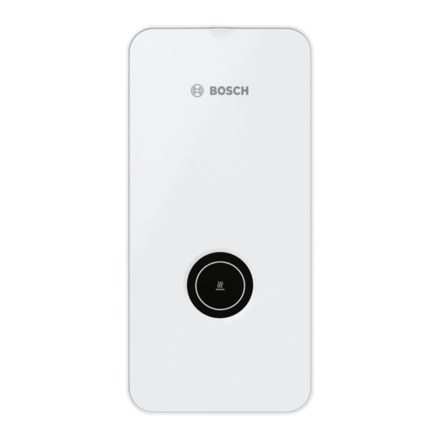
Operating panel

[1] Operating status LED
Before commissioning the appliance

Risk of electric shock!
▶ The initial commissioning of the appliance must be carried out by a qualified expert who will provide the client with all the information required for its proper functioning.
NOTICE
Risk of damage to the appliance!
▶ Never turn on the appliance if there is no water. This could damage the heating element.
Switching the appliance on/off
Switching On
▶ Turn on a hot water tap.
The appliance turns on. The water heats up while it circulates through the appliance.
Switching Off
▶ Turn off the hot water tap.
LED status display
| LED | Status of the appliance |
| Off | Appliance switched off |
| White LED | Appliance switched on |
| White LED flashes (1x per second) | The appliance is not reaching the set temperature. The appliance has reached the power limit (→ Problems chapter). |
| White LED flashes (2x per second) | Automatic vent mode active. |
| Red LED | Malfunction in the appliance (→ Problems chapter). |
| White LED flashes 4x | The water inlet temperature is higher than the temperature selected on the appliance (Solar). The appliance does not heat up. |
| White LED flashes (1x every 4 seconds) | Holiday mode active (only possible through the APP). The appliance does not heat the water. |
Table 2
Temperature control
This appliance is thermostatic and with a factory-defined fixed temperature control set at 50°C.

Risk of scalding!
Scalding in children, the elderly or adults due to contact with hot water.
▶ Always check the water temperature by hand.
| Length of time for scalding to occur | ||
| Temperature | Elderly people/ children under 5 years of age | Adults |
| 50°C | 2.5 minutes | more than 5 minutes |
| 52°C | less than 1 minute | 1.5 to 2 minutes |
| 55°C | Roughly 15 seconds | Roughly 30 seconds |
| 57°C | Roughly 5 seconds | Roughly 10 seconds |
| 60°C | Roughly 2.5 seconds | Less than 5 seconds |
| 62°C | Roughly 1.5 seconds | Less than 3 seconds |
| 65°C | Roughly 1 second | Roughly 1.5 seconds |
| 68°C | Less than 1 second | Roughly 1 second |
Table 3
Start-up after a power failure
After a power failure,
▶ Turn on the hot water tap completely and let the water flow until hot water comes out.
Start-up after a water supply cut
▶ Turn off the appliance's circuit breaker at the electrical cabinet.
▶ Turn on a hot water tap and keep it on until the air is completely purged out of the pipework.
▶ Turn off the hot water tap.
▶ Turn on the appliance circuit breaker at the electrical cabinet.
▶ Turn on the hot water tap and let the water flow for at least for a minute.
Only after this operation will it be safe to use the appliance again.
Cleaning
▶ Do not use abrasive or solvent-based cleaning agents, or alcohol-based products.
▶ Do not use steam cleaning appliances.
▶ Clean the exterior with mild cleaning agents.
▶ Clean the remains of dirt or limescale.
Connectivity
The appliance supports Wi-Fi connectivity.
For more information on accessories available for this appliance, please consult the appliance catalogue.
Customer Service
Whenever you contact the Customer Service Hotline, please provide the serial number of the appliance (SNR/TTNR).
The serial number for the appliance can be found on the plate inside of the front cover.
Installation (only for specialised and qualified technicians)
Important information
The installation, electrical connection and the initial commissioning are operations that must be carried out by qualified experts only.
In order to ensure the correct installation and operation of the appliance, please observe all regulations, technical guidelines and applicable national and regional directives.

Risk of electric shock!
Before beginning the installation work:
▶ Turn off the electric supply at the electrical cabinet.
▶ Turn off the cold water supply.
Risk of scalding due to hot water!
If you use preheated water, the temperature of the hot water may exceed the maximum temperature established for the appliance and cause scalding, in which case;
▶ Use a thermostatic valve to limit the temperature of the water entering the appliance.
NOTICE
Risk of damage to property!
Risk of irreparable damage to the appliance.
▶ Only remove the appliance from the packaging when in the installation location.
▶ Handle the appliance with care.
NOTICE
Risk of damage to property!
Risk of damage to heating elements.
▶ Carry out the water connections first.
▶ Carry out the electrical connections, with the circuit breaker turned off, ensuring that it is duly grounded.
▶ Purge the appliance completely before turning on the residual current device, by turning on the hot water tap completely and let the water circulate in the appliance for 1 minute.
Test for delivery temperature performance
The appliance must be tested in accordance with PCA at 50°C - limited water heater, see figure below.

Fig. 5 Figure A.1 - Option 1 - simple water heater (AS 3498)
[1] Inlet water.
[2] Inlet pressure (Pi) and inlet temperature (Ti).
[3] Water heater.
[4] Flow rate to sanitary fixtures used primarily for personal hygiene purposes.
[5] Pipework to sanitary fixtures used primarily for personal hygiene purposes.
[6] Valves to control water flow for the purposes of testing.
[7] Delivery temperature (represents water temperature at the outlet from sanitary fixtures used primarily for personal hygiene purposes.
Choose the installation location
NOTICE
Risk of damage to the appliance!
Never support the appliance on the water connections and/or by the electric feed cable.
▶ Choose a wall which is strong enough to support the weight of the appliance.
▶ Use the fixing materials supplied with the appliance.
▶ Mount the appliance in a vertical position with the hydraulic connections below.
Installation location
| ▶ | Comply with current guidelines. |
| ▶ | Install the appliance in a room where the ambient temperature never drops below 0°C. |
| ▶ | Do not install the appliance in locations with an altitude above 2000 m above sea level. |
| ▶ | Install the appliance near to the most used hot water tap, so as to reduce thermal loss and wait times. |
| ▶ | Install the appliance in a location where it is possible to carry out maintenance. |
| ▶ | Install the appliance taking into account the specific voltage on the data plate. |
Protection zone
When installation is required in a wet area please comply with the following installation standard:
- AS/NZS 3000; clause 6.2.4.5 and table 6.1.
Unpack and remove the cover of the appliance
NOTICE
Risk of damage to the appliance! In the event of transportation damages,
▶ Do not install the appliance.
Before carrying out any installation,
▶ Pay attention to the instructions given in this manual.
▶ Perform the installation of the appliance according to the following images.
▶ Unpack the appliance.
▶ Dispose of the packaging according to the recycling systems applicable in the country.
▶ Remove the front fascia of the appliance.

▶ Loosen the fixing screw at the front of the appliance.

▶ Loosen and remove the front fascia of the appliance.

▶ Turn around the hot water pipe.
▶ Open the side fixing parts of the hydraulic block.

▶ Remove the hydraulic block from the back.

Water connection
NOTICE
Damages to the installation!
Damages to the water pipework.
▶ Ensure that the pipework can withstand a maximum pressure of 10 bar and a maximum temperature of 100°C.
NOTICE
Danger of damage to the appliance!
The existence of sand can cause a reduction in the flow rate and its obstruction in more serious cases.
▶ Purge the water circuit before installing the appliance.
This appliance is intended to be permanently connected to the mains water supply.
Water connections to the appliance can be vertical or horizontal, brass plugs/caps are supplied to blank off unused inlet and outlet fittings. All other fittings must be in accordance with AS/NZS3500 and local regulatory requirements. The plumbing connection for this appliance must comply with standards set out in AS3500.4 and PCA.
Accessories
The accessories supplied with the device must be used, as shown in Fig. 12.

[1] Cold water inlet (G ½")
[2] Hot water outlet (G ½")
▶ Only use taps and accessories with capacity to operate in a closed circuit (under pressure).
Identify the water connections
▶ Make sure the cold and hot water pipes are duly identified, in order to avoid confusion.

[1] Cold water inlet (G ½")
[2] Hot water outlet (G ½")
▶ Install the water connection accessories.
During the installation of the shut-off valve,
▶ Make sure that the shut-off valve handle is facing upwards.

[1] Cold water inlet (G ½")
[2] Hot water outlet (G ½")
To mount the appliance on the wall
▶ Remove the plastic part from the back of the appliance.

▶ Use the back of the appliance as a hole pattern.
▶ Support the appliance on the cold water accessory to facilitate marking on the wall.
▶ Mark the mounting point, ensuring that the appliance is in a level and vertically position.

For models with Aquastop system (TR...A),
▶ Ensure the vertical alignment of the appliance. The appliance cannot be tilted by more than 1°.
▶ Separate the fixing parts.

▶ Fix into the wall the fixing parts for the appliance.

▶ Attach the back of the appliance to the wall.

Electrical installation of the appliance
It is possible to connect the power cable in three different positions;
- Upper connection
- Lower Connection
- Lower connection for short cables


The opening of the cable conduit must fit the power cable perfectly. If the cable conduit is damaged during assembly, the holes must be covered in a watertight manner.
▶ The cable conduit must be cut according to the diameter of the power cable.

▶ Insert the connection cable at least 40 mm inside the appliance, unless you are using the lower connection site for short cables.
▶ Pass the power cable through the cable conduit, ensuring tightness.

▶ If the distance between the appliance and the wall is 2-8 mm, the appliance must be levelled using the upper mounting fixing.

If the appliance is not perpendicular to the wall,
▶ Use spacers at the bottom to level the appliance.
▶ The spacers should be placed at the back of the appliance.

[1] Spacers
▶ Level the appliance with the upper mounting fixing and the spacers, if the distance between the appliance and the wall is 8-16 mm.

If the appliance is not securely fixed to the wall,
▶ Use the screws to fix the spacers to the wall.

After levelling the appliance,
▶ Tighten the fixings so that the appliance is secured to the wall.

Hydraulic block assembly
▶ Position the hydraulic block into the back of the appliance.
▶ Position the water inlet and outlet pipes into the sealing membrane.

▶ Adjust the hydraulic block until it is firmly secured at the back of the appliance.

▶ Place the bonded washers onto the water connections.
▶ Tighten the water connections.
▶ Check if there are leaks.
The air must be purged from the appliance
After all of the hydraulic connections to the appliance have been carried out, purge the air from the appliance,
▶ Turn on the cold water supply.
▶ Turn on a hot water tap for 1 minute to purge air from the appliance.

[1] Hot water tap
Appliance configuration
Risk of electric shock!
Before configuring the appliance,
▶ Turn off the electrical supply at the electrical cabinet.
It is possible to configure several parameters on the same appliance.
▶ Use the electronic Jumpers provided to carry out the different appliance configurations.

▶ Save the removed Jumpers for future changes or installations.

Setting maximum temperature
▶ Use Jumper J5 to set the maximum temperature of the appliance, according to the table below.

Hot water temperature calibration

Risk of electric shock!
Before configuring the appliance,
▶ Use personal protective equipment to avoid electric shock.
▶ Never touch the live parts of the appliance!
Before starting the hot water temperature calibration on the appliance:
▶ Ensure that the device has no errors.
Risk of electric shock!
▶ Disconnect the power supply before carrying out any work on the device.
If the hot water temperature at the tap closest to the appliance does not match the temperature selected on the appliance, you can adjust it as follows;
▶ Remove the appliance's front panel (→ Fig. 6).
▶ Remove the appliance's front cover (→ Fig. 8).
▶ Switch the power supply on to adjust the appliance.
▶ Remove Jumper 1 (J1) [1].
After the LED flashes 5x times, the appliance enters the temperature calibration mode.
▶ Press the reset button [2]. Temperature increases by 1°C.

▶ Check the water temperature at the closest hot water tap with a thermometer.
If you need to increase the temperature:
▶ Press the reset button [2]. The maximum temperature value is + 5°C.
| Level | LED blinks | °C temperature |
| 1 | 1x | 0°C |
| 2 | 2x | + 1°C |
| 3 | 3x | + 2°C |
| 4 | 4x | + 3°C |
| 5 | 5x | + 4°C |
| 6 | 6x | + 5°C |
Table 5
To exit the temperature calibration mode:
▶ Return Jumper 1 (J1) to its initial position.
▶ Place the front cover and front panel back on the appliance.
If you exceed the adjustment time (15 minutes) or if the appliance shows an error:
▶ Enter temperature calibration mode again.
To enter the temperature calibration mode;
▶ Place Jumper 1 (J1) in its position.
▶ Wait 5 seconds.
▶ Start the calibration process.
Calibration example
| Temperature on the device | Temperature on the tap | Calibration |
| 50°C | 47°C | + 3°C |
Table 6
Electrical connection
(only for specialised and qualified technicians)
General information
Risk of electric shocks!
▶ Disconnect the power supply before carrying out any work on the device.
All regulation, control and safety equipment of the device is connected at the factory and supplied ready for operation.
Lightning strike!
▶ The device must have a separate connection in the distribution box and be protected by a 30 mA fault current circuit breaker and earth lead. A overvoltage protection device must also be provided in areas characterised by frequent lightning strikes.
Electrical connection
The electrical mains connection terminal can be assembled at the top or at the bottom of the appliance. The electrical connection can be made in 3 different ways,
- Upper connection (Fig. 33)

- Lower Connection (Fig. 34)

- Lower connection for short cables (Fig. 35)


▶ Carry out the electrical connections, according to the position of the power cable. The layout of the electrical cables must be positioned in accordance with the images.
Maximum length for short cables
For installations using the lower connection for short cables, the length of the cables must not exceed 70 mm.

[A] > 150 mm
[B] ≤ 70 mm
The opening of the cable conduit must fit the power cable perfectly. If the cable conduit is damaged during assembly, the holes must be covered in a watertight manner.
Procedure for lower connection for short cables
▶ Press the snap fits with a screwdriver.

▶ Remove the appliance's sealing membrane.

▶ Pull the end of the cable conduit to its full extent to protect the electrical cable.

▶ Cut the end of the cable conduit according to the diameter of the electrical cable so as to guarantee a tight fit.
▶ Pass the power cable through the cable conduit guaranteeing a minimum of 10 mm of insulating cover for the electrical cable.


[A] ≥ 10 mm
▶ Replace the sealing membrane on the back of the appliance.
▶ Tighten the electrical cables into the electrical terminal of the appliance.

▶ Position the electrical cable so that it is not in the way of where the appliance's central screw is inserted and it allows the appliance cover to be correctly fitted.
Install the appliance cover
Connect the cable to the operating panel
Before attaching the appliance cover,
▶ Connect the cable from the operating panel to the electronic board.

▶ Place the cover on the appliance.

▶ Tighten the fixing screw on the cover of the appliance.

Commissioning of the device
(only for approved specialists)
First commissioning of the appliance
NOTICE
Risk of damage to the appliance!
The initial commissioning of the appliance must be carried out by a qualified expert who will provide the customer with all the information required for its proper operation.
▶ Turn on the cold water inlet.
▶ Check the tightness of all connections.
▶ Turn on the appliance circuit breaker at the electrical cabinet.
Initial operation
▶ Completely turn on a hot water tap and let the water flow for at least 1 minute, until the LED stops blinking (2x per second). Only after this period (for safety reasons) will the appliance start heating the water.
Check the correct operation of the user interface
After turn on a hot water tap,
▶ Check if the operation LED lights up.
If the operation LED does not light up,
▶ Check if the cable from the operating panel is correctly connected to the electronic board (→ Fig. 43).
If the appliance does not heat the water
▶ Remove the aerator from the hot water taps.
▶ Remove the flow rate reducer from the shower.
▶ Removing the flow limiter from the appliance (→ Removing/Replacing the flow limiter).
Information for the customer
▶ Inform the customer about the how appliance works and provide instructions on how to use it.
▶ Give the customer all the printed documents for the appliance.
Removing/Replacing the flow limiter
The appliance needs a minimum water pressure and flow rate to start (→ Tab. 8).
If the appliance does not start up, due to the low water flow rate in the domestic water installation,
▶ Remove the flow limiter from the appliance.

Maintenance
(only for specialised and qualified technicians)
Risk of personal or material damage!
Before commencing any maintenance work:
▶ Switch off the electric supply.
▶ Close the water shut-off valve.
Inspection, maintenance and repairs,
| ▶ | It is the customer's responsibility to call an expert to carry out repairs and inspections. |
| ▶ | Inspection, maintenance and repairs must only be carried out by authorised experts. |
| ▶ | Use only original spare parts from the manufacturer. The manufacturer will assume no responsibility for damage caused by spare parts not supplied by the manufacturer. |
| ▶ | Order spare parts from the spare parts catalogue for this appliance. |
| ▶ | During maintenance work, replace removed joints with new ones. |
| ▶ | After carrying out maintenance work, press the restart button to restart the appliance. |
NOTICE
Damage to the appliance!
▶ For safe and environmentally compatible operation, maintenance and cleaning must be carried out at least once every 12 months in accordance with Maintenance chapter.
Problems
Electrical shock!
▶ Disconnect the power supply before carrying out any work on the appliance.
▶ Installation, repairs and maintenance must only be carried out by qualified experts.
The following table describes the solutions to possible problems (some of the solutions should only be carried out by experts).
| Problem | Cause | Solutions |
| Volumetric flow rate of water too low. | The tap or shower filter is clogged. | Remove the filter, wash or remove the limescale. |
| The appliance's water filter is clogged. | Ask a qualified expert to clean the water filter. | |
| Possible flow blockage caused by the appliance's volumetric flow rate limiter. | Request a qualified expert to remove the volumetric flow rate limiter(→ Removing/Replacing the flow limiter Chapter). | |
| The appliance does not turn on. | The residual current device tripped in the electrical cabinet. | Check the residual current device in the electrical cabinet. |
| The appliance does not heat the water. | Holidays mode is active (white LED blinks 1x every 4 seconds) | Deactivate Holidays mode, only possible via the APP. |
| The water does is not heating up sufficiently. | The power limit was reached (white LED flashing 1x per second). | Reduce the flow rate of the water tap. |
| Flow rate too high and/or cold water inlet temperature too low (winter). | Ask a qualified expert to adjust the flow rate by means of the angle valve. Check the volumetric flow rate limiter or use another to reduce the water flow rate. | |
| Sometimes the appliance temporarily stops supplying hot water. | The appliance detects air in the water and momentarily shuts off the heating elements (white LED flashing 2x per second). | Wait a few seconds while the appliance purges the air from the system. |
| The (red) LED is flashing | Malfunction in the appliance. | Close and open the hot water tap. If the error remains; Contact customer support. |
Table 7 Problems
Technical information
Technical data
| Technical characteristics | Unit | TR4001 L 13 | TR4001 L 18 | TR4001 L 27 | |||
| Rated voltage | V | 400V | 415V | 400V | 415V | 400V | 415V |
| Rated output power | kW | 13 | 14 | 18 | 19.4 | 27 | 27.5 |
| Rated current | A | 18.8 | 19.5 | 26 | 27 | 39 | 39.7 |
| Fuse protector/RCD | A | 20 | 20 | 25 | 32 | 40 | 40 |
| Minimum cable cross-sectional area[1]) | mm[2] | See footnote1) | |||||
| Water mixed at rated output with temperature increase of; | |||||||
| 12°C up to 38°C (without volumetric flow rate limiter) | l/min | 8.1 | 8.7 | 9.8 | 10.5 | 14.6 | 14.9 |
| 12°C up to 38°C (with volumetric flow rate limiter) | l/min | 7.6 | 7.6 | 7.6 | 7.6 | 9.4 | 9.4 |
| 12°C up to 50°C | l/min | 5.6 | 6.0 | 6.7 | 7.2 | 10.0 | 10.2 |
| Pressure loss with temperature rise of: | |||||||
| 12°C up to 50°C (without volumetric flow rate limiter) | bar | 0.7 | 0.8 | 1.0 | 1.2 | 2.3 | 2.3 |
| 12°C up to 50°C (with volumetric flow rate limiter) | bar | 1.2 | 1.4 | 1.7 | 2.2 | 5 | 5 |
| Minimum appliance start-up flow rate2) | l/min | 2.5 | 2.5 | 2.5 | |||
| Minimum appliance start-up pressure[3]) | MPa (bar) | 0.04 (0.4) | 0.04 (0.4) | 0.04 (0.4) | |||
| Application field for water with specific electrical resistance at 15°C. |  cm cm | ≥ 1 300 | ≥ 1 300 | ≥ 1 300 | |||
| Water's maximum conductivity at 15°C | μS/cm | ≤ 769 | ≤ 769 | ≤ 769 | |||
| Nominal pressure | MPa (bar) | 1.0 (10) | 1.0 (10) | 1.0 (10) | |||
| Maximum allowable infeed temperature | °C | 50°C | 50°C | 50°C | |||
| Volumetric flow rate limiter | l/min (cor) | 7.6 (White) | 7.6 (White) | 9.4 (Yellow) | |||
| Maximum impedance at the connecting point | | 0,347 | 0,170 | 0,117 | |||
[1] ) The cross sectional area of the connection cable must be in accordance with the power rating of the appliance and the specific requirements of AS/NZS 3000.
[2] ) The first time the appliance is commissioned, the minimum water flow rate should be 3.5 l/min.
[3] ) The pressure drop in the mixer should be added to this value.
Table 8 Technical characteristics
Water quality
All Bosch appliances are constructed from high quality materials and components and all are certified for compliance with relevant parts of Australian gas, electrical and water standards.
While Bosch water heaters are warranted against manufacturing defects, the warranty is conditional upon correct installation and use, in accordance with detailed instructions provided with the heater.
In the case of the water supplied to the heater, it is important that the water quality be of acceptable standard.
In regions where water is characterized by high chloride and calcium carbonate levels, it is essential to analyse it and, if necessary, treat the water to prevent eventual damage to appliance heating elements.
In the areas of Australia where water maybe supplied either fully or partly from bores, artesian wells, or similar, one or more of the important limits may well be exceeded and the heater could, therefore, be at risk of failure.
If the installer is uncertain about the water quality in the area, they should always contact the Bosch Customer Contact Centre Phone 1300 30 70 37 and request to speak with the technical team.
Alternatively, you can contact us using the online form at:
https://www.bosch-homecomfort.com/au/en/residential/customer-support/contact-us/
Or via post to:
Robert Bosch Aust Pty Ltd, Attention TT Warranty Department, Locked Bag 66, Clayton South, Victoria, 3169. Claims received by post will take longer to process and we encourage you to call.
If it is determined that the water supply does not meet quality standards, the Bosch warranty will not apply.
Environmental protection and disposal
Environmental protection is a fundamental corporate strategy of the Bosch Group.
The quality of our products, their economy and environmental safety are all of equal importance to us and all environmental protection legislation and regulations are strictly observed. We use the best possible technology and materials for protecting the environment taking account of economic considerations.
Packaging
- Polystyrene
Clean polystyrene material may be recycled. Recycle, incinerate, or landfill, as appropriate, in an approved facility.
Dispose of in accordance with Local, State & Federal EPA waste regulations.
Polystyrene packaging is not recyclable in yellow recycling bins. May be landfilled in Australia.
To confirm local practices, contact your local Council. For disposal locations visit https://recyclemate.com.au/ select material and location. - Cardboard
Dispose in your kerbside recycling bin or a dedicated cardboard recycling bin. - Soft Plastic Wrapping
Dispose of soft plastic wrapping packaging in your general waste bin.
Used appliances
Used appliances contain valuable materials that can be recycled.
The various assemblies can be easily dismantled. Synthetic materials are marked accordingly. Assemblies can therefore be sorted by composition and passed on for recycling or disposal.
Old electrical and electronic appliances
![]() Do not dispose in your kerbside bins.
Do not dispose in your kerbside bins.
Electronic products can contain toxic chemicals and pose health and safety risks for the people handling your kerbside waste. They are a cause of contamination in kerbside bins and can pose a fire risk in collection trucks and at material recovery facilities.
Keep devices out of your kerbside bins and always safely dispose of them at a nominated collection point. If there are no options close to you for appropriate disposal, contact help@recyclemate.com.au for further guidance on appropriate disposal practices in your state or jurisdiction.
Warranty Period and Coverage
The following is a list of the classes of products sold by Bosch which are covered by this voluntary warranty, and the warranty periods which apply in each case.
| Product Group | Description | |||
| Electric Water Instantaneous Unit | Models | Application | Parts | Labour |
| 3 Phase Electric Water Instantaneous Hot Water | TR4001 | Domestic | 5 year | 5 year |
| TR7001 | Domestic | 5 year | 5 year | |
| TR8501 | Domestic | 5 year | 5 year |
How to Make a Warranty Claim
If a Product fails within the warranty period, the end user must stop using the Product and make a claim as soon as possible, in any event before the end of the Warranty Period (see Deadlines for Submitting Warranty Claims below).
To make a warranty claim under this voluntary warranty, call the Bosch Customer Contact Centre (in Australia on ph: 1300 307 037. Please be ready to provide the model and serial number, date of installation, purchase details and a full description of the problem. Alternatively, for claims in Australia, you can post details of your claim to Robert Bosch (Australia) Pty Ltd, Attn HC Warranty Department, Locked Bag 66, Clayton Sth, Victoria, 3169. Claims received by post will take longer to process and we encourage you to call. Bosch may refer you to one of its Bosch Warranty Authorised Service Dealers.
Proof of purchase and purchase date, as well as proof of installation and proper commissioning by a licensed installer, may be required by Bosch or an authorised service technician.
All warranty service calls will be conducted by an authorised service technician during normal business hours. Bosch will not accept claims under this voluntary warranty for attendance and repair of the Product by third parties not authorised by Bosch.
If the installer is uncertain about the water quality in the area, they should always contact the Bosch Customer Contact Centre Phone 1300 30 70 37 and request to speak with the technical team.
Alternatively, you can contact us using the online form at https://www.boschhomecomfort.com/au/en/residential/customer-support/contact-us/. ;
Or via post to Robert Bosch (Australia) Pty Ltd, Attention HC Warranty Department, Locked Bag 66, Clayton South, Victoria, 3169. Claims received by post will take longer to process and we encourage you to call
More details about how Bosch handles your personal information is included in its https://www.bosch.com.au/privacy-policy/
Bosch Contact Details
This warranty is offered by Robert Bosch (Australia) Pty Ltd (ACN 004 315 628) of 1555 Centre Road, Clayton, Victoria 3168. Please call the Customer Contact Centre on 1300 30 70 37 in Australia if you have any queries in relation to this warranty or contact us using the online form at https://www.boschhomecomfort.com/au/en/residential/home/
Explanation of symbols and safety instructions
Explanation of symbols

In warnings, signal words at the beginning of a warning are used to indicate the type and seriousness of the ensuing risk if measures for minimising danger are not taken.
The following signal words are defined and can be used in this document:

DANGER indicates that severe or life-threatening personal injury will occur.
WARNING indicates that severe to life-threatening personal injury may occur.
CAUTION indicates that minor to medium personal injury may occur.
NOTICE indicates that material damage may occur.

The info symbol indicates important information where there is no risk to people or property.
| Symbol | Meaning |
| ▶ | a step in an action sequence |
| → | a reference to a related part in the document |
| • | a list entry |
| – | a list entry (second level) |
Table 1
Explanation of symbols and safety instructions
General safety instructions
 General description
Read this manual carefully and act accordingly.
| ▶ | Before utilisation, please read and keep the user manuals (appliance, etc.). |
| ▶ | Pay attention to the safety and warning notices. |
| ▶ | Follow national and regional regulations, technical regulations and guidelines. |
| ▶ | Please document the works that were carried out. |
Use as intended
The appliance is intended for private and domestic use only. The appliance can also be used in non-domestic environments, for example offices, as long as the use is for domestic purposes. Any utilisation other than what is outlined is not permitted.
| ▶ | The appliance should be used and assembled as outlined in the text and images. We do not accept any liability for damages that are caused due to the failure to comply with the instructions in this manual. |
| ▶ | This appliance should be used up to a maximum altitude of 2,000 m above sea level. |
| ▶ | The appliance must be installed in a room protected from below-zero temperatures. |

In the event of a malfunction or water leak in the appliance,
▶ Immediately turn off the electrical supply to the appliance.
▶ Turn off the cold water supply to the appliance immediately.
Installation
These installation instructions are for experts specialised in water installations, electrical engineering and heating techniques. All instructions from the manuals must be observed. Failure to comply with these instructions can result in material damage, personal injury and danger to life.
| ▶ | Read the installation instructions (heat generator, heating regulator, etc.) before installation. |
| ▶ | Comply with the current legal provisions in the country in which the appliance is installed, and those of the local energy and water supply companies. |
| ▶ | Install the appliance into a cold-water circuit containing water for human consumption (closed circuit). |
| ▶ | The installation must only be carried out by an authorised contractor. |
Explanation of symbols and safety instructions
▶ Always switch off the electric current before opening the appliance.
▶ To avoid dangerous situations, repairs and maintenance may only be carried out by an authorised technician.
▶ This appliance is of protection classI and must be connected to the protective conductor.
▶ The appliance must be permanently connected to the electrical installation. The cross sectional area of the wire must be equivalent to the power to be installed.
Danger of electric shocks!
The appliance's grounded pipes can make it seem that the appliance is grounded.
▶ The appliance must be connected to the protective conductor cable.
▶ To guarantee compliance to relevant safety regulations, an all-pole separator must be fitted during installation, according to chapter Technical data. The contact opening must be at least 3 mm.
▶ Make sure that the maximum and minimum inlet water pressure is compliant with the value specified by the manufacturer (→ chapter Technical data ).
▶ Water taps and accessories must have been approved for operation with appliances that function in a closed circuit (under pressure).
▶ The temperature of the cold water can be pre-heated with a maximum limit of 50°C.
Risk of scalding!
▶ If the appliance uses pre-heated water, the selected or limited temperature can be exceeded. In these cases, use a thermostatic valve to limit the temperature of the preheated cold water.
▶ The specific electrical resistance of the water cannot be less than 1300  cm. Ask your local water supply supplier to inform you of the electrical resistance level of the water.
▶ The appliance is suitable for supplying water to multiple usage points, including water for baths.
▶ Before installing the appliance, make sure that the electrical connection is disconnected and that the water supply is closed.
▶ Prepare the water connections before the electrical connections.
| ▶ | Make only the openings on the back of the appliance that are required for its installation. If it is a new installation, unused holes must be sealed so as to ensure water tightness. |
| ▶ | Live parts must not be accessible after the assembly. |
| ▶ | Do not use abrasive, caustic or alcohol-based cleaning agents. |
| ▶ | Do not use steam cleaning appliances. |
Installation
The installation of this appliance shall conform to the Plumbing Code of Australia (PCA).
For continued safety of this appliance it must be installed, operated and maintained in accordance with the manufacturer's instructions.
This appliance must only be installed in accordance with the acceptable plumbing configurations specified in these instructions. Failure to do so may result in conditions where delivery temperature control is inadequate.
This appliance may deliver water at high temperature. Refer to the plumbing code of Australia (PCA), local requirements and installation instructions to determine if additional delivery temperature control is required.
Inspection, cleaning and maintenance
The user is responsible for ensuring the heating system is safe and environmentally compatible.
Missing or inadequate inspection, cleaning and maintenance can lead to bodily injury and up to the danger of death and property damage.
We recommend the signing of a contract for the annual inspection and responsive maintenance with a specialized and authorized contractor.
The work can only be carried out by a specialized and authorized contractor that has to carry out all the work and immediately eliminate the detected faults.
Maintenance
▶ Maintenance must only be carried out by an authorised contractor.
▶ Always disconnect the appliance from the electric current before carrying out any maintenance work.
▶ The user is responsible for the safety and environmental compatibility of the installation and/or maintenance.
▶ Only original spare parts should be used.
Safety of appliances with electrical connection for domestic use and similar purposes
To avoid danger due to electrical appliances, in line with AS/ NZS 60335.1:2022, the following specifications are valid:
"This appliance is not intended for use by persons (including children) with reduced physical, sensory or mental capabilities, or lack of experience and knowledge, unless they have been given supervision or instruction concerning use of the appliance by a person responsible for their safety. Children should be supervised to ensure that they do not play with the appliance."
"If the connection cable is damaged, it must be replaced by the manufacturer, its customer service personnel or a similarly qualified person in order to avoid danger."
Standards, regulations and directives
Observe all regulations and standards during installation and operation:
- Regulations for the electrical installation and for the connection to the electrical supply network
- Regulations for the electrical installation and for the connection to the remote signalling and wireless network
- National standards and regulations
This water heater must be installed in accordance with:
- Manufacturers Installation Instructions
- AS/NZS 3500.4 "National Plumbing & Drainage Code"
- AS/NZS 3000 "Wiring Rules"
- Municipal Building Codes
- Any other State or Federal Statutory Regulations
Robert Bosch (Australia) Pty Ltd
Thermotechnology Division
1555 Centre Road
Clayton Victoria 3168
Australia
Phone: 1300 30 70 37
Fax: 1300 30 70 38
www.bosch-homecomfort.au
New Zealand
Phone: 0800 54 33 52
Fax: 0800 54 33 55
www.bosch-homecomfort.nz
Documents / Resources
References
Contact Us | Bosch Thermotechnology
Recycle Mate
Home | Bosch Home Comfort Group
![www.bosch.com.au]() Privacy policy | Bosch in Australia
Privacy policy | Bosch in AustraliaHome | Bosch Home Comfort Group
Bosch Hot Water & Heating - Residential | Bosch Thermotechnology
Bosch Hot Water & Heating - Residential | Bosch Thermotechnology
Download manual
Here you can download full pdf version of manual, it may contain additional safety instructions, warranty information, FCC rules, etc.
Download Bosch Tronic 4000, TR4001 L 13 ESOB, TR4001 L 18 ESOB, TR4001 L 27 ESOB Manual
Advertisement


Need help?
Do you have a question about the Tronic 4000 and is the answer not in the manual?
Questions and answers