Mackie SRM450, SRM450V2 Service Manual
- Service manual (24 pages) ,
- User manual (21 pages) ,
- User's manual and warranty registration (20 pages)
Advertisement
INTRODUCTION
 SERVICE ON THIS EQUIPMENT IS TO BE PERFORMED BY EXPERIENCED REPAIR TECHNICIANS ONLY
This manual contains basic service information. It is essential that you have a copy of the user's manual as this contains the complete operating instructions.
SERVICE TECHNICAL ASSISTANCE
Mackie Designs, Service Technical Assistance, is available 8AM - 5PM PST, Monday through Friday for Authorized Mackie Service Centers, at 1-800-258-6883. Feel free to call with any questions and speak with a carefully-calibrated technician. If one is not available, leave a detailed message and a qualified Mackoid will return your call asap.
DISCLAIMER
The information contained in this manual is proprietary to Mackie Designs, Inc. The entire manual is protected under copyright and may not be reproduced by any means without express written permission from Mackie Designs, Inc.
Block Diagram

Specifications
Low-Frequency Transducer
| Diameter | 300mm (12") |
| Voice Coil Diameter | 63.5mm (2.5") |
| Sensitivity (1W@1m) | 98 dB |
| Nominal Impedance | 8 ohms |
| Power Handling | 300W |
| Frequency Range | 50Hz – 3000Hz |
High-Freq Driver and Horn
| Diaphragm Diameter | 44.5mm (1.75") |
| Exit Throat Diameter | 24.5mm (1") |
| Diaphragm Material | Titanium |
| Sensitivity (1W@1m) | 106 dB |
| Nominal Impedance | 8 ohms |
| Power Handling | 150W |
| Frequency Range | 1000Hz – 20,000Hz |
Low-Freq Power Amplifier
| Rated Power | 300 watts |
| Rated THD | < 0.1% |
| Cooling: | Convection Extrusion |
| Design: | Class G, Parametric Servo Feedback |
High-Freq Power Amplifier
| Rated Power | 100 wa tts |
| Rated THD | < 0.1% |
| Cooling: | Convection Extrusion |
| Design: | Conventional Class AB |
System specs
| Input Type | Balanced Differential |
| Input Impedance | Line: 20k ohms |
| Input Protection | RFI and level protected |
| Sensitivity | Line: +4 dBu (centered) |
| Mic: –36 dBu | |
| Maximum Input Level | Line: +22 dBu |
| Low-Cut Frequency | 75Hz, Second-order filter |
| EQ | Peaking +3 dB @ 55Hz, +3 dB @ 20kHz |
| Over-Excursion Protection | Second-Order High-Pass Filter |
| Thermal Protection | Amplifier shutdown, autoreset |
| Low-Line Voltage Shut Down: | 60% Nominal line |
| Acoustic Freq Response: | 45Hz – 20,000Hz |
| Low-Freq –3 dB Point: | 55Hz |
| Maximum SPL @ 1m: | 123 dB |
| Low-Freq Crossover: | 24 dB/octave, time offset corrected |
| High-Freq Crossover: | 24 dB/octave |
| Crossover Frequency: | 1600Hz |
| Driver Protection | Independent LF and HF compressors |
| Low-Freq Roll-Off: | Dynamic-signal level dependent |
| Accessory Interface | ±15V DC |
| Operating Temp Range | –10ºC - 45ºC (14ºF - 113ºF) |
Line Input Power
| US | 120V, 60Hz |
| Europe | 230V, 50Hz |
| Japan | 100V, 50/60Hz |
Disclaimer
Since we are always striving to make our products better by incorporating new and improved materials, components, and manufacturing methods, we reserve the right to change these specifications at any time without notice.
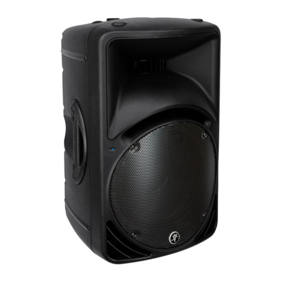
Overview
The SRM450 is an active two-way loudspeaker system capable of extremely high sound pressure levels.
The Transducers
The SRM450 active monitors feature a 12" high-power low-frequency woofer and a 1.75" titanium diaphragm high-output precision compression driver. This high frequency driver is mounted on an acoustically non-resonant exponential waveguide, providing a wide, controlled dispersion and precise reproduction of the critical upper mid-range and high frequencies. The result is an unbelievably smooth off-axis response that allows everyone in the audience to experience the same high-resolution audio no matter where they are seated. Each driver has been specifically designed by our engineers for optimum performance in the lightweight high-strength cabinet.
FR Series Power Amplifiers
To power these beautiful things, each SRM450 includes two of our acclaimed FR Series "Fast Recovery" power amplifiers. Our exclusive design uses low negative feedback, yet allows the amplifiers to maintain low distortion and stability and to quickly recover when driven into clipping. The amplifiers include the following features:
- The low-frequency amplifier produces up to 540 watts peak (300 continuous) before clipping.
- The high-frequency amplifier produces up to 150 watts peak (100 continuous) before clipping.
- Each amplifier has its own compressor circuit that acts when the input signal is large enough to cause clipping, distortion and excessive voice coil heat. The compressor will automatically decrease the input signal to a safe level. The compressor in the lowfrequency amp works independently from that in the high-frequency amp.
- The low-frequency amp uses a servo feedback loop which senses the current flowing in the woofer coil. This controls the low-frequency response and maintains low distortion at high output levels.
- The low-frequency amplifier also has a sweeping filter. This will automatically move the low cut-off frequency up or down depending on the amplifier output. For example, if the amplifier is below clipping, the low-frequency cut-off point is 55Hz. As it approaches clipping, this shifts up smoothly to 120Hz, providing more power reserves and less distortion before clipping. This happens quickly and continuously, protecting the amplifer and the woofer and reducing any noticable distortion.

Although the amplifiers have these protection circuits, you must still make sure the PEAK light is not blinking often or continuously. If it is, turn down your mixer faders, or preamplifier gain, or turn down the SRM450 LEVEL control.
The Crossover
The built-in electronic crossover is a 24 dB/octave Linkwitz-Riley design. Although more expensive than other crossover designs, the benefits provided by the Linkwitz-Riley design have been well documented. These benefits include:
- Absolutely flat frequency response throughout the bandpass, without the characteristic ripple near the crossover point exhibited by other designs.
- The sharp 24 dB per octave roll-off of the filters ensures that the transducers aren't reproducing frequencies outside of their capabilities.
- The acoustic sum of the two driver responses is unity at the crossover frequency, resulting in perfect power response.
- Our heroic engineers have worked carefully to ensure that the SRM450 also provides perfect phase response. This diligence has yielded phenomenal accuracy, even if you are standing 20 feet away.
The Cabinet
The SRM450 cabinet was designed to be the strongest molded composite cabinet on the planet. This material is as strong as concrete, and rigid enough to prevent unwanted vibrations in the cabinet. It has built-in fly points for hanging, and a socket in the bottom for mounting on a tripod stand. Although it is an exceptional choice for installed sound situations, its light weight and durable finish also make it ideal for portable sound system use. The asymmetrical trapezoidal design of the cabinet makes it easy to use as a floor wedge for stage monitor applications.
Safety test
You must perform the following leakage test before returning the unit to your customer. Take every safety precaution to protect yourself while doing this test.
- Make a small loading RC circuit as shown in the diagram below, and connect the AC volt meter between the AC power source ground and any exposed metal on the unit under test.
- Connect the unit under test to an AC power source using a ground-lift adaptor, leaving the unit's safety ground floating. Turn the unit on.
- The meter reading should be less than 750mVAC (note: this is equivalent to 0.5mA of leakage current).
- Flip the plug over in the receptical so the hot and neutral are swapped. Verify that the reading is still less then 750mVAC.
- If either reading is greater than 750mVAC, then you must investigate and repair the unit before returning it to your customer.

Bias adjustment
The Amplifier Bias of every SRM450 must be carefully adjusted as follows.
- Place the SRM450 on its side so that the heatsink fins are horizontal.
- Connect the power cord and turn it on, with no input signal applied. Make sure that the TIMED TURNOFF switch is OFF.
![]()
- Let it sit this way for an hour or more to allow the heatsink temperature to rise. You can play music through to speed things up. If you have a thermometer, the bias adjustment procedure is best done when the heatsink temperature is 45 to 50 deg C.
- Turn off the SRM450 and remove the power cord.
- Remove the complete amplifier/heatsink assembly from the plastic speaker case but leave all wires connected, including the speaker wires. Support the amplifier so it can be safely turned on again.
- Replace the power cord and turn on the amplifier and take care not to touch any exposed live AC components.
- No input signal is applied.
- Low frequency amplifier bias adjustment: While the heatsink is still warm, measure the DC voltage across the 2 pins of J21. Adjust R202 until a reading of 4mV to 4.5mV is reached. See sheet 2 for the location of J21 and R202.
![]()
When finished adjusting, secure R202 with a small drop of paint, such as nail varnish. - High frequency amplifier bias adjustment:
Measure the DC voltage across the 2 pins of J20. Adjust R212 until a reading of 4mV to 4.5mV is reached.
![]()
Secure R212 with a small drop of paint.


- This completes the adjustment procedure. Reassemble and perform a full test.

SRM-450 PARTS LIST
Parts Numbering guide
040- Cables
055- Finished PCB Assy
100- Pots and resistors
200- Capacitors
300- Semiconductors
400- Jacks/Connectors
500- Switches
510- Fuses
550- Chassis Metalwork
600- Transformers
601- Inductors
610- Wires and Cables
640- AC line cords
700- Hardware
760- Knobs/Plastic
770- Fans
790- Misc./Packing
800- Printed Material
860- EPROM
| PART# | DESCRIPTION |
| 090-132-xx | Master Parts |
| 080-136-00 | Cabinet subassembly |
| 055-227-00 | Main Board |
Components noted with this symbol shall be replaced only by the component specified. This is required to maintain product safety.
Master Parts List 090-132-xx

Cabinet Subassembly 080-136-00
| PART NO. | DESCRIPTION | REV | QTY | NOTES |
| 055-280-00 | PC B ASSY LED | 1 | ||
| 080-156-00 | SA C ABLE PC B LED BLK/WHT | 1 | ||
| 080-157-00 | SA SUPPO RT DRIVER THRO AT | 1 | ||
| 080-158-00 | SA HARNESS BLU & BLU/BLK | 1 | ||
| 080-159-00 | WIRE YEL WOOFER | 1 | ||
| 490-025-00 | COMP DRIVER | 1 | Comp driver | |
| 490-042-00 | WOOFER SRM450 | 1 | Woofer | |
| 490-047-00 | SRM FRO NT C ASE MRB | 1 | Front case | |
| 490-048-00 | SRM REAR C ASE MRB | 1 | Rear case | |
| 490-052-00 | PO LE MNT KNO B | 1 | ||
| 490-053-00 | FO AM D BLK&WHT | 1 | ||
| 550-408-00 | TOP HANDLE PA SPKR | 1 | Top handle | |
| 550-410-00 | GRILL 12IN SPKR AC TIVE | B | 1 | Grill |
| 700-123-00 | SC REW SIDE HDL G RIP MNTG | 4 | ||
| 700-124-00 | SC REW HDL MNTG TO C ASE | 4 | ||
| 700-125-00 | SC REW WO O FER | 8 | ||
| 701-021-00 | 6X3/8 PHP PLASTITE BLK | A | 4 | |
| 701-026-00 | SCREWS FOR CASE | 17 | ||
| 701-027-00 | SCREW BAC K PANEL | 12 | ||
| 701-028-00 | SCREW FEET G RILL C D-THR | 13 | ||
| 701-029-00 | SC REW PC B ASSY LED | 1 | ||
| 705-031-00 | FLYING HW INS NUTS G ALV | 8 | ||
| 705-032-00 | FLYING HW INS NUTS BLK | 2 | ||
| 710-049-00 | WASH HDL MTNG TO C ASE | 4 | ||
| 710-050-00 | WASH FLAT WO O FER | 8 | ||
| 710-051-00 | FLYING HW INS WASH G ALV | 8 | ||
| 710-052-00 | FLYING HW INS WASH BLK | 2 | ||
| 712-068-00 | FLYING HW INSERTS | 10 | ||
| 712-069-00 | GROMMET LEAD WIRE | 1 | ||
| 750-015-00 | FEET | 3 | ||
| 760-115-00 | SIDE HANDLE GRIP SRM450 | A | 2 | |
| 760-116-00 | PLASTIC SIDE HANDLE | A | 2 | |
| 780-135-00 | GASKET WOOFER SRM450 | 1 | Woofer Gasket | |
| 780-138-00 | FOAM DA C O MP DR TO CASE | 1 | ||
| 780-139-00 | FO AM D C O MP D TO THRO AT | 1 | ||
| 780-140-00 | GASKET FOR SPEAKER | 1 | ||
| 790-010-00 | BAG 20 X 7 X 48 4MIL G USS | 1 | ||
| 800-141-00 | BOX SRM450 | 1 | ||
| 810-088-00 | CARDBD BTTM SRM450/C 300 | 1 | ||
| 810-089-00 | TRIANG INS SRM450/C 300 | 1 | ||
| 840-249-00 | LBL LO G O SPKR FRO NT | A | 1 | |
| 840-250-00 | LBL LO G O SPKR RUNNING MAN | A | 1 | |
| 840-251-00 | LBL SPKR PWR AC TIVE | A | 1 | |
| 840-314-00 | LBL INSERT COVER SRM450 | A | 10 |
055-227-00 Main pcb assembly


Components noted with this symbol shall be replaced only by the component specified. This is required to maintain product safety.

SRM450 Pole Mount Insert Rework Instructions
 Note: These instructions are to be used along with Mackie kit P/N 020-006-00 to repair SRM450s which already have the pole mount insert stripped out. The pole mount bolt assembly (bolt, knurled brass insert and alignment bushing) must still be with the unit as the parts will be recycled and also used during the rework.
- Remove stripped out pole mount bolt assembly. This can be done by hand – one or two sharp jerks on the bolt should pull the assembly free.

Pole Mount Bolt Assembly - Unscrew the defective brass knurled insert from the bolt and remove the black metal bolt bushing.
- Screw the metric nut (M6x1.00) onto the insert installation tool until it stops.
- Screw the new replacement threaded brass insert onto the end of the installation tool until it stops against the nut.
![]()
Replacement Insert
(Mackie P/N 712-073-00) - Slide the black metal bushing down onto the insert tool so it is behind the nut (shoulder on the bushing should be away from the nut) – this will be used to align the new insert during installation.


Installation Tool Assembly
Insert Installation - Place the tool (insert first) into the pole mount hole.
- Using the small pipe, gently tap the bushing into place so it fits snug. The bushing only needs to be partially installed (as a guide) since it will be removed shortly. Remove the pipe.

Tapping bushing into place with pipe - Attach drill or similar device to insert tool and drive insert into position clockwise. Insert will stop against shoulder when at correct installed depth.
![information]() NOTE: DO NOT drive the insert in fast! Doing so will damage the plastic hole and decrease the effectiveness of the repair. Drive the insert in relatively slowly while applying downward pressure. You will feel the new threaded insert (self-tapping) catch, start cutting and then bottom out once the shoulder contacts the bottom of the hole. Once you feel this, STOP! DO NOT force the insert past this bottoming out point or you will strip out the new threads.
NOTE: DO NOT drive the insert in fast! Doing so will damage the plastic hole and decrease the effectiveness of the repair. Drive the insert in relatively slowly while applying downward pressure. You will feel the new threaded insert (self-tapping) catch, start cutting and then bottom out once the shoulder contacts the bottom of the hole. Once you feel this, STOP! DO NOT force the insert past this bottoming out point or you will strip out the new threads. - Reverse the drill and back the tool out. A quick, sharp twist once you start to back the tool out will break the tool free from the insert. You do not need to remove the tool slowly as with the installation. The metal bushing will easily pull out along with the installation tool.
- Using a small flathead screwdriver or similar tool, remove the plastic chips from inside the pole mount hole on the bottom of the speaker. If compressed air is available, blow out the inside of the new threaded insert to remove any plastic chips that may be present.
![]()
Plastic burrs from insert installation - Take the installation tool out of the drill and remove the metric nut from the threaded end of the tool.
- To reinstall the black metal bushing, screw the installation tool back into the insert a few threads and slide the bushing back down the tool – with the shoulder of the insert up. Again, using the piece of pipe, permanently tap the insert into place until it bottoms against the shoulder. Take care to reinstall the bushing straight.
- Remove the insert tool and pipe.
- Reinstall the original pole mount bolt. There may be some additional friction in the threads. This is due to plastic burrs protruding slightly through the slots in the insert – this friction will decrease the more the pole mount bolt is used.


SRM450/C300 stabilizing feet

Documents / ResourcesDownload manual
Here you can download full pdf version of manual, it may contain additional safety instructions, warranty information, FCC rules, etc.
Advertisement


Need help?
Do you have a question about the SRM450 and is the answer not in the manual?
Questions and answers