Table of Contents
Advertisement
Quick Links
Air Conditioning Control System - Optional Parts
Mounting Attachment for Wall Surface Installation
Installation Manual
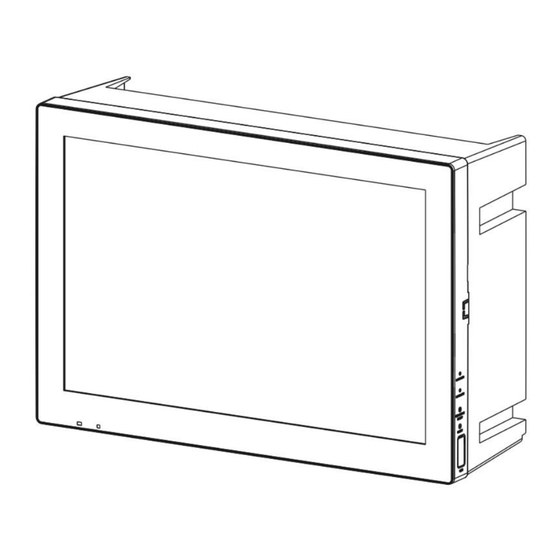
PAC-YK92TB
Before installing the product, please read this Installation Manual carefully to ensure proper operation.
Retain this manual for future reference.
Applicable Model
For distribution to dealers and contractors only
Contents
··························································································
············································································
········································································
en-1
AE-C
··································································
····································································
······························································
·························································
····················································
·········································
·······························································
······················································
·················································
························································
········································
········································
·································································
3
5
5
5
6
7
9
9
9
10
10
10
10
14
16
17
WT10528X01
Advertisement
Table of Contents

Related Manuals for Mitsubishi Electric PAC-YK92TB


Summary of Contents for Mitsubishi Electric PAC-YK92TB
-
Page 1: Table Of Contents
Applicable Model AE-C Air Conditioning Control System - Optional Parts Mounting Attachment for Wall Surface Installation Installation Manual For distribution to dealers and contractors only Contents PAC-YK92TB ·································································· Safety precautions ·························································································· 1. Parts ···································································· 1-1. Supplied parts ······························································ 1-2. Commercial parts ·························································... -
Page 2: Manual Download
Manual Download http://www.mitsubishielectric.com/ldg/ibim/ en Go to the above website to download manuals, select model name, then choose language. de Besuchen Sie die oben stehende Website, um Anleitungen herunterzuladen, wählen Sie den Modellnamen und dann die Sprache aus. Rendez-vous sur le site Web ci-dessus pour télécharger les manuels, sélectionnez le nom de modèle puis choisissez la langue. es Visite el sitio web anterior para descargar manuales, seleccione el nombre del modelo y luego elija el idioma. -
Page 3: Safety Precautions
Safety precautions ►Thoroughly read the following safety precautions prior to installation. ►Observe these precautions carefully to ensure safety. : indicates a hazardous situation which, if not avoided, could result in death or serious injury. : indicates a hazardous situation which, if not avoided, could result in minor or moderate injury. - Page 4 ■ Precautions for installation Properly dispose of the packing materials. Plastic bags pose a suffocation hazard to children. Installation work must be performed by the dealer or qualified personnel according to the instructions in the Installation Manual. Improper installation work or installation work performed by the user may cause trouble.
-
Page 5: Parts
1. Parts 1-1. Supplied parts The package contains the following items. • Transport them to the installation site as packed. Item Shape Quantity Remarks Mounting attachment for wall-surface installation D-2 LAN extension cable Installation Manual ― (this manual) 1-2. Commercial parts Item Shape Quantity... -
Page 6: External Dimensions
1-3. External dimensions Unit: mm (in.) 304 (11-31/32) 292 (11-1/2) 94 (3-23/32) 30° 165 (6-1/2) 8.4 (11/32) 244 (9-5/8) 122 (4-13/16) *1 For installation with screws *2 For installation with anchors *3 For installation with screws *4 Service cover WT10528X01 en-6... -
Page 7: Overview Of Installation
2. Overview of installation (A) Mounting attachment (supplied part D-1) (B) Screw (for installing the mounting attachment) (commercial part S-1) (C) AE-C (D) Roundhead screw (supplied with AE-C) en-7 WT10528X01... - Page 8 Note • Leave the LAN extension cable (supplied part D-2) connected to the LAN1 port on the AE-C when no LAN cable is connected to the LAN1 port. (A) LAN extension cable WT10528X01 en-8...
-
Page 9: Selecting The Installation Site
3. Selecting the installation site Install the product where the weight of the product can be held. Installation in a place with insufficient strength or improper installation may cause the product to fall, causing injury. Install the mounting attachment on a wall that can hold the weight of the AE-C and the mounting attachment (total 3.8 kg (9 lbs)). -
Page 10: Installation
4. Installation To reduce the risk of injury, electric shock, or malfunction, do not touch the edges of the product. To reduce the risk of injury, do not touch burrs of knockout holes. 4-1. Progress of building construction and construction conditions None. - Page 11 Note • When no LAN cable is connected to the AE-C, unscrew the screw on the bottom and remove the service cover. *1 Service cover *2 Screw 2. Install the mounting attachment (supplied part D-1) on a wall. • When anchoring the mounting attachment, use M6 anchors. (B) Screw (for installing the mounting attachment) (commercial part S-1/S-2) *1 Orient the mounting attachment according to the UP mark shown inside the mounting attachment.
- Page 12 3. Route the cables through the cable access holes. • To prevent malfunction caused by electrical interference noise, do not put the AC power cable together with the M-NET cable or the LAN cable in the same conduit tube. *1 LAN cable *2 M-NET transmission cable *3 AC power cable Note...
- Page 13 • Leave the LAN extension cable (supplied part D-2), which is for maintenance, connected to the LAN1 port on the AE-C when no LAN cable is connected to the LAN1 port. Put the LAN extension cable in the mounting attachment as shown below. Route the LAN extension cable Install the AE-C on the mounting Put the LAN extension cable in...
-
Page 14: Routing Cables From The Bottom Of The Mounting Attachment
4-2-2. Routing cables from the bottom of the mounting attachment Steps 1. Cut out the thin-walled part on the bottom and the knockout hole of the service cover to make cable access holes. • Unscrew the screw on the bottom, and remove the service cover. •... - Page 15 Note • Leave the LAN extension cable (supplied part D-2), which is for maintenance, connected to the LAN1 port on the AE-C while no LAN cable is connected to the LAN1 port. Put the LAN extension cable in the mounting attachment as shown below. Route the LAN extension cable Install the AE-C on the mounting Put the LAN extension cable in...
-
Page 16: Maintenance
5. Maintenance When performing maintenance while no LAN cable is connected to the AE-C, remove the service cover on the bottom, take out the LAN extension cable (supplied part D-2), and connect it to the computer for maintenance. *1 Service cover *2 Screw Note •... -
Page 17: Electrical Wiring
6. Electrical wiring Refer to the Installation Manual for the AE-C for details of wiring. en-17 WT10528X01... - Page 20 Please be sure to put the contact address/telephone number on this manual before handing it to the customer. 872C769A10 HEAD OFFICE: TOKYO BLDG., 2-7-3, MARUNOUCHI, CHIYODA-KU, TOKYO 100-8310, JAPAN MANUFACTURER: MITSUBISHI ELECTRIC CORPORATION Air-conditioning & Refrigeration Systems Works 5-66, Tebira 6 Chome, Wakayama-city, 640-8686, Japan WT10528X01_en...
Need help?
Do you have a question about the PAC-YK92TB and is the answer not in the manual?
Questions and answers