Advertisement
Available languages
Available languages
Quick Links
M I T S U B I S H I R o o m
M o d e l M L P -4 4 9 W U
I N S T A L L A T I O N M A N U A L
C o rre c t i n s t a l l a t i o n i s e s s e n t i a l f o r g o o d p e rf o rm a n c e o f t h e p ro d u c t a n d s a f e t y . B e s u re t o re a d t h i s m a n u a l b e f o re
i n s t a l l a t i o n .
T H E FO L L O W I N G
S H O U L D A L W A Y S B E O B S E R V E D FO R S A FE T Y
• Be sure to read T E FOLLOWING S OULD ALWA S BE OBSERVED FOR SAFET
• Be sure to observe the arnings and cautions specified here as they include important items related to safety.
• After reading this manual, be sure to keep it together ith the OPERATING INSTRUCTIONS for future reference.
D o n o t p e rf o rm
i n s t a l l a t i o n b y y o u rs e l f ( u s e r) .
Incomplete installation could cause fire or electric shock, injury due to the unit
falling, or leakage of ater. Consult the dealer from hom you purchased
the unit or a qualified installer.
P e rf o rm
t h e i n s t a l l a t i o n s e c u re l y re f e rri n g t o t h e i n s t a l l a t i o n m a n u a l .
Incomplete installation could cause fire or electric shock, injury due to the
unit falling, or leakage of ater.
1. C o m p o n e n t s
● This kit contains the follo ing parts.
Q'ty
Remark
2. C h e c k s b e f o re i n s t a l l a t i o n
● Before installing the grille (1), make sure the indoor unit is square ith the ceiling opening (or parallel to the all-ceiling joint).
● C h e c k t h a t t h e 4 p o i n t s f o r s e c u ri n g t h e g ri l l e ( 1) o n t h e i n d o o r u n i t a re l e v e l w i t h t h e c e i l i n g s u rf a c e .
Use the installation template supplied ith the indoor unit to arrange the position of the indoor unit so that the 4 points for securing the grille (1) are level ith
the ceiling surface ith a tolerance of 1/8 in. (3 mm). (Fig. 1)
Note: Instructions for using the installation template are provided on the installation template itself.
N o t e : I f t h e m i s a l i g n m e n t b e t w e e n t h e 4 p o i n t s f o r s e c u ri n g t h e g ri l l e ( 1) a n d t h e c e i l i n g s u rf a c e i s m o re t h a n 1/ 8 i n . ( 3 m m ) , t h e i n t a k e g ri l l e m a y
n o t o p e n o r c l o s e p ro p e rl y .
● Make sure the follo ing is completed: insulation for the refrigerant pipes, drainage pipes, etc. and iring connections and arrangements.
● Check that any material like ceiling insulation does not protrude to the ceiling opening.
Points for securing grille (1)
Points for securing grille (1)
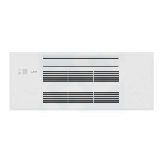
A i r C o n d i t i o n e r O p t i o n a l G ri l l e
(1) Grille
1
Fi g . 1
before installation.
WARNING
(Could lead to death, serious injury, etc.)
I n s t a l l t h e u n i t s e c u re l y i n a p l a c e w h i c h c a n b e a r t h e w e i g h t o f t h e
u n i t .
If the installation location cannot bear the eight of the unit, the unit could
fall causing injury.
Be sure to use the parts provided or specified parts for the installa-
t i o n w o rk .
The use of defective parts could cause fire or electric shock, injury due to
the unit falling, or leakage of ater.
U s e a p p ro p ri a t e p ro t e c t i v e e q u i p m e n t a n d t o o l s f o r s a f e t y .
Failure to do so could cause injury.
(2) Scre
6
M5 × 16
Drain pan
Ceiling surface
Point for securing grille (1)
(3) Scre
1
4 × 12
Ma e sure these surfaces are ush
w i t h e a c h o t h e r ( 0 - 1/ 8 i n . [ 0 - 3 m m ] ) .
E n -1
Advertisement

Related Manuals for Mitsubishi Electric MLP-449WU


Summary of Contents for Mitsubishi Electric MLP-449WU
- Page 1 M I T S U B I S H I R o o m A i r C o n d i t i o n e r O p t i o n a l G ri l l e M o d e l M L P -4 4 9 W U I N S T A L L A T I O N M A N U A L C o rre c t i n s t a l l a t i o n i s e s s e n t i a l f o r g o o d p e rf o rm a n c e o f t h e p ro d u c t a n d s a f e t y .
- Page 2 3 . G ri l l e i n s t a l l a t i o n 1. Open the intake grille by pressing the 2 tabs on the intake grille to the direction indicated by arro s. (Fig. 2) Slide the 2 shafts in ard and remove the intake grille from the shafts.
- Page 3 3 . G ri l l e i n s t a l l a t i o n 10. ook the safety strings of the side covers L/R to the grille and install the side covers. (Fig. 8) • Make sure that the catches of the side covers L/R are engaged securely. (Fig. 8) •...
-
Page 4: M A N U A L D E I N S T A L A C I Ó N
Rejilla opcional para aire acondicionado de sala MITSUBISHI M o d e l o M L P -4 4 9 W U M A N U A L D E I N S T A L A C I Ó N Una instalaci n correcta es esencial para el buen funcionamiento del producto su seguridad. - Page 5 3. Instalaci n de la rejilla 1. Abra la rejilla de entrada presionando las 2 leng etas de dicha rejilla en la direcci n indicada por las flechas. (Fig. 2) Deslice los 2 ejes hacia el interior y retire la rejilla de entrada de los ejes. (Fig. 3) Retire los cordones de seguridad de la rejilla de entrada y ret rela.
- Page 6 3. Instalaci n de la rejilla 10. Enganche los cordones de seguridad de las cubiertas laterales I/D a la rejilla e inst lelas. (Fig. 8) • C ompruebe que los cierres de las cubiertas laterales I/D estén enganchados de forma segura. (Fig. 8) • A bra la tapa de la pantalla y compruebe que las marcas de posici n estén alineadas correctamente.
- Page 7 Grille optionnelle du climatiseur individuel MITSUBISHI Modèle MLP-449WU NOTICE D’INSTALLATION Seule une installation correcte vous permettra d’obtenir un fonctionnement optimal conforme aux règles de sécurité. Veuillez lire ce manuel attentivement avant de procéder à l’installation. INSTRUCTIONS A RESPECTER A TOUT MOMENT PAR MESURE DE SECURITE • Veuillez lire les “INSTRUCTIONS A RESPECTER A TOUT MOMENT PAR MESURE DE SECURITE”...
-
Page 8: Installation De La Grille
3. Installation de la grille 1. Ouvrez la grille d’admission en appuyant sur les 2 languettes de la grille d’admission dans le sens indiqué par les flèches. (Fig. 2) Glissez les 2 axes vers l’intérieur et retirez la grille d’admission des axes. (Fig. 3) Retirez les cordons de sécurité... - Page 9 3. Installation de la grille 10. Accrochez les cordons de sécurité des caches latéraux G/D à la grille et montez les caches latéraux. (Fig. 8) • Assurez-vous que les taquets des caches latéraux G/D sont bien engagés. (Fig. 8) • Ouvrez le couvercle de l’affichage et vérifiez que les repères de positionnement sont correctement alignés.
- Page 12 EAD OFFICE: TO O BUILDING, 2-7-3, MARUNOUC I, C I ODA- U, TO O 100-8310, APAN DT79B455 01...
Need help?
Do you have a question about the MLP-449WU and is the answer not in the manual?
Questions and answers