Advertisement
Table of Contents
HEAT PUMP UNIT
SERVICE MANUAL
[Model Name]
EHGT17D-YM9ED
[Service Ref.]
EHGT17D-YM9ED.UK
HEAT PUMP UNIT
MAIN REMOTE
CONTROLLER
R32
Revision:
• DISASSEMBLY PROCEDURE
has been modified in
REVISED EDITION-A.
OCH722 is void.
CONTENTS
1. SAFETY PRECAUTION ................................... 2
2. SPECIFICATIONS ............................................ 8
3. PART NAMES AND FUNCTIONS .................. 9
4. OUTLINES AND DIMENSIONS ..................... 10
5. WIRING DIAGRAM ......................................... 11
6. FIELD WIRING ............................................... 13
7. WATER SYSTEM DIAGRAM ......................... 14
8. CONTROLS ................................................... 17
9. TROUBLESHOOTING ................................... 43
10. DISASSEMBLY PROCEDURE ...................... 78
11. SUPPLEMENTARY INFORMATION .............. 93
12. SERVICE AND MAINTENANCE ................... 94
PARTS CATALOG (OCB722)
December 2020
No. OCH722
REVISED EDITION-A
Advertisement
Table of Contents

Related Manuals for Mitsubishi Electric EHGT17D-YM9ED


Summary of Contents for Mitsubishi Electric EHGT17D-YM9ED
-
Page 1: Table Of Contents
HEAT PUMP UNIT December 2020 No. OCH722 SERVICE MANUAL REVISED EDITION-A [Model Name] EHGT17D-YM9ED Revision: • DISASSEMBLY PROCEDURE has been modified in REVISED EDITION-A. OCH722 is void. [Service Ref.] EHGT17D-YM9ED.UK CONTENTS 1. SAFETY PRECAUTION ........2 2. SPECIFICATIONS ..........8 3. -
Page 2: Safety Precaution
SAFETY PRECAUTION MEANINGS OF SYMBOLS DISPLAYED ON THE UNIT This mark is for R32 refrigerant only. Refrigerant type is written on nameplate of heat pump unit. WARNING In case that refrigerant type is R32, this unit uses a flammable refrigerant. (Risk of fire) If refrigerant leaks and comes in contact with fire or heating part, it will create harmful gas and there is risk of fire. - Page 3 [1] Warning for service (1) Do not alter the unit. (2) For installation and relocation work, follow the instructions in the Installation Manual and use tools and pipe components specifically made for use with refrigerant specified in the installation manual. (3) Ask a dealer or an authorized technician to install, relocate and repair the unit.
- Page 4 [4] Cautions for unit using R32 refrigerant Pay careful attention to the following points. (1) Information on servicing (1-1) Checks on the Area Prior to beginning work on systems containing flammable refrigerants, safety checks are necessary to ensure that the risk of ignition is minimized.
- Page 5 (3) Repair to intrinsically Safe Components Do not apply any permanent inductive or capacitance loads to the circuit without ensuring that this will not exceed the permissible voltage and current permitted for the equipment in use. Intrinsically safe components are the only types that can be worked on while live in the presence of a flammable atmos- phere.
- Page 6 b) Isolate system electrically. c) Before attempting the procedure, ensure that: • mechanical handling equipment is available, if required, for handling refrigerant cylinders; • all personal protective equipment is available and being used correctly; • the recovery process is supervised at all times by a competent person; •...
- Page 7 [5] Service tools Use the below service tools as exclusive tools for R32 refrigerant. Tool name Specifications Gauge manifold · Only for R32 · Use the existing fitting specifications . (UNF1/2) · Use high-tension side pressure of 5.3MPa·G or over. Charge hose ·...
-
Page 8: Specifications
SPECIFICATIONS Product specification Model name EHGT17D-YM9ED Nominal domestic hot water volume 170 L Overall unit dimensions 1750 × 595 × 680 mm (Height × Width × Depth) Weight (empty) 181 kg Weight (full) 360 kg Refrigerant The amount of refrigerant 0.9kg... -
Page 9: Part Names And Functions
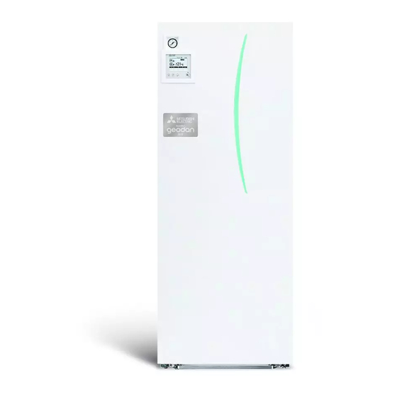
PART NAMES AND FUNCTIONS Component Parts <Overall> Part name DHW outlet pipe Cold water inlet pipe Water pipe (Space heating return connection) Water pipe (Space heating flow connection) Brine pipe (Bore hole return connection) Brine pipe (Bore hole flow connection) Control and electrical box Main remote controller Plate heat exchanger (Refrigerant - Water) -
Page 10: Outlines And Dimensions
OUTLINES AND DIMENSIONS <Unit: mm> 4-1. Technical Drawings G1/2 209.5 301.6 376.3 460.6 471.5 505.6 550.6 <TOP> HANDLE MANOMETER MAIN CONTROLLER TERMINAL BLOCK FRONT PANEL HANDLE HANDLE <BACK> <LEFT SIDE> <FRONT> <RIGHT SIDE> Letter Pipe description Connection size/type DHW outlet connection 22 mm/Compression Cold water inlet connection 22 mm/Compression... -
Page 11: Wiring Diagram
WIRING DIAGRAM CNPWM CN01 Immersion heater (1Ph1kW)(Option) (WH) (BK) Power supply Power supply to Booster heater to Immersion heater 3~ 400V 50Hz ~/N 230V 50Hz CNP1 TBO.1 (WH) <How to use TBO.1 to 4> ECB2 Connect them using either way as shown below. ECB1 Tool 2WV2b... - Page 12 Symbol Name Symbol Name Terminal block (Power supply) Motor for Compressor ECB1 Earth leakage circuit breaker for booster heater Brine Pump Motor Earth leakage circuit breaker for immersion heater High Pressure Switch ECB2 (Option) Flow Switch Water circulation pump 1 63HS High Pressure Sensor (Space heating &...
-
Page 13: Field Wiring
FIELD WIRING Breaker abbreviation Meaning ECB1 Earth leakage circuit breaker for booster heater ECB2 Earth leakage circuit breaker for immersion heater (option) Terminal block 1 Affix label A that is included with the manuals near each wiring diagram for heat pump units. Wiring circuit Earth leak- breaker... -
Page 14: Water System Diagram
DHW tank capacity 170 L Mass of the unit when full 360 kg Maximum primary working pressure 2.5 bar * EN60335/Type 1000W single phase 230V 50Hz, length 460 mm. Use only Mitsubishi Electric service parts as a direct replacement. OCH722A... - Page 15 Local system 1-zone temperature control Zone1 Zone1 2-zone temperature control 1-zone temperature control with boiler Zone1 Zone1 Zone2 2-zone temperature control & Buffer tank control 1-zone temperature control (2-zone valve ON/OFF control) Zone1 Zone1 Zone2 Zone2 1. Zone1 heat emitters (e.g. radiator, fan coil unit) (local supply) 10.
- Page 16 Filling the System (Primary Circuit) 1. Check and charge expansion vessel. 2. Check all connections including factory fitted ones are tight. 3. Insulate pipework. 4. Thoroughly clean and flush, system of all debris. 5. Fill heat pump unit with potable water. Fill primary heating circuit with water and suitable anti-freeze and inhibitor as necessary. Always use a filling loop with double check valve when filling the primary circuit to avoid back flow contamination of water supply.
-
Page 17: Controls
CONTROLS 8-1. Main remote controller <Main remote controller parts> Letter Name Function Screen Screen in which all information is displayed Menu Access to system settings for initial set up and modifications. Back Return to previous menu. Confirm Used to select or save. (Enter key) Power/Holiday If system is switched off pressing once will turn system on. - Page 18 8-2. Setting the Main remote controller After the power has been connected to the heat pump units (See "6. FIELD WIRING") the initial system settings can be entered via the main remote controller. 1. Check all breakers and other safety devices are correctly installed and turn on power to the system. 2.
- Page 19 8-4. Main Settings Menu The main settings menu can be accessed by pressing the MENU button. To reduce the risk of untrained end users altering the settings accidentally there are 2 access levels to the main settings; and the service section menu is password protected. User Level –...
- Page 20 <Main Remote Controller Menu Tree> Initial Unrestricted access Installer only Main screen * Short press for 1 Zone system. Information Long press Option Forced DHW ON ( )/OFF ON ( )/Prohibited ( )/Timer ( ) Heating ON ( )/Prohibited ( )/Timer ( ) Consumed electrical energy Energy monitor Menu...
- Page 21 <Continued from the previous page.> Unrestricted access <Main Remote Controller Menu Tree> Installer only Initial Long press Main Main screen menu Standard (Heat pump & electric heater)/Heater (Electric heater only)/ Heat source setting Menu Boiler/Hybrid (Heat pump & heater/Boiler) Pump speed Service Heat pump flow rate range Password...
- Page 22 8-5. Service Menu The service menu provides functions for use by installer or service engineer. It is NOT intended the home owner alters settings within this menu. It is for this reason password protection is required to prevent unauthorised access to the service settings. The factory default password is "0000".
- Page 23 <Thermistor adjustment> This function allows adjustments to be made to the thermistor readings from −10 to 10°C in 0.5°C intervals. THW1: Thermistor (Flow water temp.) THW2: Thermistor (Return water temp.) THW5A: Thermistor (DHW tank upper water temp.) THW5B: Thermistor (DHW tank lower water temp.) THW6: Thermistor (Zone1 flow temp.)(Option) THW7: Thermistor (Zone1 return temp.)(Option) THW8: Thermistor (Zone2 flow temp.)(Option)
- Page 24 Mixing valve control 1. From the Auxiliary settings menu highlight Mixing valve control. 2. Press CONFIRM. 3. The Mixing valve control screen is displayed. 4. Use F1 and F2 buttons to set Running time between 10 to 240 seconds. The Running time equals to a period from full open of the valve (at a hot water mixing ratio of 100%) to full close (at a cold water mixing ratio of 100%).
- Page 25 <Operation settings> Heating operation This function allows operational setting of flow temperature range from the Ecodan and also the time interval at which the FTC collects and processes data for the auto adaptation mode. Menu subtitle Function Range Unit Default Flow temp.
- Page 26 Booster heater1 Booster heater2 Pump1 Pump2 Pump3 heater When additional pumps supplied locally are EHGT17D-YM9ED 3 kW 6 kW 0 kW ***(factory fitted pump) connected as Pump2/3, change setting ac- cording to specs of the pumps. Change setting to 1 kW when connecting optional immersion heater "PAC-IH01V2-E".
- Page 27 2. Settings using the main remote controller In this menu, all parameters required to record the consumed electrical energy and the delivered heat energy which is displayed on the main remote controller can be set. The parameters are an electric heater capacity, supply power of water pump and heat meter pulse.
- Page 28 <Summary of settings> This function shows the current installer/user entered settings. Abbreviation Explanation Abbreviation Explanation HWtemp DHW max. temperature Z2 mode Operation mode HWdrop DHW temperature drop - HER (Heating room temperature) HWtime DHW max. operation time - HE (Heating flow temperature) NO HW DHW mode restriction - HCC (Heating compensation curve)
- Page 29 Resetting the password If you forget the password you entered, or have to service a unit somebody else installed, you can reset the password to the factory default of 0000. 1. From the main settings menu scroll down the functions until Service Menu is highlighted.
- Page 30 8-6. Request code list Request Description Request content Unit Remarks code (Display range) Operation state Refer to 8-6-1. Detail Contents in Request Code. – Compressor-Operating current (rms) 0 to 50 Compressor-Accumulated operating time 0 to 9999 10 hours Compressor-Number of operation times 0 to 9999 100 times Discharge temperature (TH4)
- Page 31 Request Description Request content Unit Remarks code (Display range) C.B.-Capacity setting display Refer to 8-6-1.Detail Contents in Request Code. – C.B.-Setting information Refer to 8-6-1.Detail Contents in Request Code. – C.B.-Microprocessor version information Examples) Ver 5.01 → "0501" C.B.-Microprocessor version information Auxiliary information (displayed after version in- –...
- Page 32 Request Description Request content Unit Remarks code (Display range) Condensing temperature (T63HS) at the time of error −39 to +88 °C Thermostat ON time until operation stops due to error 0 to 9999 Minutes Water circulation pump 1 - Accumulated operating time (after reset) 0 to 9999 10 hours Water circulation pump 2 - Accumulated operating time (after reset)
- Page 33 8-6-1. Detail Contents in Request Code [Operation state] (Request code :" 0") Relay output state Power currently Data display Display Compressor Four-way valve Solenoid valve supplied to compressor – – – – Relay output state Operation mode Operation mode Display Operation mode STOP •...
- Page 34 [Actuator output state] (Request code :"54") Data display Actuator output state 1 Actuator output state 2 Actuator output state Actuator output state Compressor is Display Four-way valve Compressor Display warming up [Error content (U9)] (Request code :"55 ") Data display Error content 1 Error content 2 Error content...
- Page 35 [Outdoor unit -– Capacity setting display] (Request code : "70") Data display Capacity [Outdoor unit – Setting information] (Request code : "71") Setting information 1 Data display Display Defrost mode Setting information 1 Standard Setting information 2 For high humidity Setting information 2 Single-/ Heat pump/...
- Page 36 FTC switch setting display (Request code: 162 to 166) 0: OFF 1: ON 0: OFF 1: ON SW1, SW2, SW3, SW4, SW5 SW1, SW2, SW3, SW4, SW5 Display Display 00 00 00 40 00 01 00 41 00 02 00 42 00 03 00 43 00 04...
- Page 37 FTC switch setting display (Request code: 162 to 166) 0: OFF 1: ON 0: OFF 1: ON SW1, SW2, SW3, SW4, SW5 SW1, SW2, SW3, SW4, SW5 Display Display 00 80 00 C0 00 81 00 C1 00 82 00 C2 00 83 00 C3 00 84...
- Page 38 Output signal display (Request code: 175/553) Please refer to Table 2 on relevant wiring diagram whilst using the following. 0: OFF 1: ON 0: OFF 1: ON Display Display xx 40 xx 00 xx 01 xx 41 xx 02 xx 42 xx 43 xx 03 xx 04...
- Page 39 Output signal display (Request code: 175/553) Please refer to Table 2 on relevant wiring diagram whilst using the following. 0: OFF 1: ON 0: OFF 1: ON Display Display xx C0 xx 80 xx C1 xx 81 xx C2 xx 82 xx C3 xx 83 xx C4...
- Page 40 0: OFF 1: ON Output signal display (Request code: 175/553) Display Please refer to Table 2 on relevant wiring diagram whilst using the following. 40 xx 41 xx 0: OFF 1: ON 42 xx 43 xx Display 44 xx 00 xx 45 xx 01 xx 46 xx...
- Page 41 Input signal display (Request code: 176/554) Please refer to Table 1 on relevant wiring diagram whilst using the following. 0: OFF (open) 1: ON (short) 0: OFF (open) 1: ON (short) Display Display 00 00 00 40 00 01 00 41 00 02 00 42 00 03...
- Page 42 Water circuit only operation Indoor unit only operation When in water circuit only operation the FTC controller board has control functions. Water circuit Necessary <Heater> Heat pump Not necessary Heating for DHW and space heating is provided by the heater. Main remote controller Necessary •...
-
Page 43: Troubleshooting
TROUBLESHOOTING 9-1. Troubleshooting <Summary of self diagnosis based on error codes and service procedures> Present and past error codes are logged, and they can be displayed on the main remote controller. Please refer to the table below and subsequent explanations to diagnose and remedy typical problems that may occur in the field. Unit Condition Error Code Action... - Page 44 9-4. Self diagnosis and action ■ Error Codes (FTC controller board) Check if DIP SW is set correctly. (Refer to "9-8. FUNCTION OF SWITCHES".) Error code Title and display conditions Possible Cause Diagnosis and action Circulation water temperature overheat Insufficient system head Refer to table in "9-6.
- Page 45 Error code Title and display conditions Possible Cause Diagnosis and action P1/P2/L5/LD FTC thermistor failure Connector/terminal wire has become Visually check the terminals and connec- Note: The thermistors subject to failure can be detached or loose wiring. tions and reattaches appropriate. checked in “Request code: 567”...
- Page 46 Error code Title and display conditions Possible Cause Diagnosis and action Heating operation error THW1 has become detached from its Visually inspect location and reattach as Note: “3” is displayed in “Request code: 567” in holder. necessary. “Running information”. <Heating/FS> Booster heater fault Electrically test to determine fault.
- Page 47 Error code Title and display conditions Possible Cause Diagnosis and action Low primary circuit (Zone2 side) flow rate Insufficient system head If more head required either add a pump of the same size or replace existing pump. detected by flow switch Reduced flow in primary water circuit Check circulation pump (See "9-6.
- Page 48 Error code Title and display conditions Possible Cause Diagnosis and action E3/E5 Main remote controller communication failure 1. 2 or more main remote controllers have 1. Only connect 1 main remote controller to 1 (Transmission error) been connected to the FTC. FTC board.
- Page 49 Error Codes (Controller circuit board) Code Error Cause Action 1. No voltage is supplied to terminal block (TB1) of 1. Check following items. heat pump unit. a) Power supply breaker a) Power supply breaker is turned off. b) Connection of power supply terminal block (TB1) b) Contact failure or disconnection of power sup- c) Connection of power supply terminal block (TB1) ply terminal...
- Page 50 Code Error Cause Action Open/short of heat pump unit thermis- 1. Disconnection or contact failure of connectors 1. Check connection of connector (TH3, TH32, TH34 tors Controller circuit board: TH3, TH32, TH34, TH7 TH7) on the controller circuit board. (TH3: (TH3, TH32, TH34, TH7 and TH8) Power board: CN6 Check connection of connector (CN6) on the...
- Page 51 Code Error Cause Action Detailed Input current sensor error/ 1. L1-phase open 1. Check the field facility for the power supply. codes L1-phase open error • Decrease in input current 2. Disconnection or loose connection between TB1 2. Check the wiring between TB1 and noise filter through heat pump unit and noise filter circuit board circuit board.
- Page 52 9-5. Troubleshooting by inferior phenomena Fault symptom Possible cause Explanation - Solution Main remote controller 1. There is no power supply to main remote 1. Check LED2 on FTC. (See "5. WIRING DIAGRAM".) display is blank. controller. (i) When LED2 is lit. Check for damage or contact failure of the main remote controller wiring.
- Page 53 Contact your Mitsubishi Electric dealer. 7. Immersion heater cut-out tripped. 7. Check immersion heater thermostat and press reset button, located on im- mersion heater boss, if safe.
- Page 54 Contact your Mitsubishi Electric dealer. 8. Incorrectly sized heat emitter. 8. Check the heat emitter surface area is adequate Increase size if necessary.
- Page 55 Annual Maintenance It is essential that the heat pump unit is serviced at least once a year by a qualified individual. Any spare parts required should be purchased from Mitsubishi Electric. NEVER bypass safety devices or operate the unit without them being fully operational.
- Page 56 Flow rate [L/min] Brine Circulation Pump Characteristics <Recommended water flow rate range> Heat pump unit Water flow rate range [L/min] EHGT17D-YM9ED 7.1-27.7 Flow rate [L/min] Water circulation pump (sanitary circuit) Measure the resistance between the terminals with a tester. (Winding temperate 20°C)
- Page 57 Part Name Checkpoints Booster heater Measure the resistance between the terminals with a tester. Thermostat (90°C) and thermal cut out (121°C) Terminal Normal Abnormal 121 °C 90 °C Manual reset 9–10 110(±35) mΩ Open or Short Thermal cut-out water thermostat 3 + 6 kW heater (400 V, 3 phase) Terminal Normal...
- Page 58 Brine pump (MBP1) Refer to the next page. Motor for compressor Measure the resistance between the terminals with a tester. (Winding temperature 20°C) (MC) EHGT17D-YM9ED Abnormal 1.65 Open or short Linear expansion valve Disconnect the connector then measure the resistance with a tester. (Winding temperature 20°C)
- Page 59 Check the fuse (F5) on controller circuit board Replace controller board (C.B) and brine pump (MBP1). Did the fuse blow? Wiring contact check Contact of brine pump connector (CNF1). Is there contact failure? Brine pump check (CNF1) EHGT17D-YM9ED UNIT Brine pump BH56N077 Measuring points Resistance pin1–pin4 1.6 MΩ...
- Page 60 <Thermistor Characteristics Charts> Low temperature thermistors • Room temperature thermistor (TH1) • Liquid refrigerant temperature thermistor (TH2) • Liquid thermistor (TH3) • Ambient thermistor (TH7) • Flow water temperature thermistor (THW1) • Return water temperature thermistor (THW2) • DHW tank temperature thermistor (THW5A/B) •...
- Page 61 Linear expansion valve (1) Operation summary of the linear expansion valve • Linear expansion valve opens/closes through stepping motor after receiving the pulse signal from the outdoor controller board. • Valve position can be changed in proportion to the number of pulse signal. <Connection between the outdoor controller board and the linear expansion valve>...
- Page 62 (3) How to attach and detach the coil of linear expansion valve <Composition> Linear expansion valve is separable into the main body and the coil as shown in the diagrams below. Main body Coil Lead wire Stopper <How to detach the coil> Hold the lower part of the main body (shown as A) firmly so that the main body does not move and detach the coil by pulling it upward.
- Page 63 9-7. Test point diagram FTC (Controller board) CNP1/OUT1 (TBO.1 1-2) Water circulation pump1 (230 V AC) OUT2 (TBO.1 3-4) Water circulation pump2 (Local supply) (230 V AC) CN01 OUT3 (TBO.1 5-6) Power supply Water circulation pump3 (3-5: 230 V AC) (Local supply) (230 V AC) CNP4/OUT14 Water circulation pump4...
- Page 64 Controller circuit board <CAUTION> TEST POINT1 is high voltage. CNDM 1–2: Input of low-level sound priority mode Function switch CN51 Function switch Abnormal history clear 1–3: External signal output Input of external contact point • Compressor operat- ing signal • Abnormal signal Model select Function switch Function switch...
- Page 65 Noise filter circuit board LO1, LO2, LO3 CNAC2 POWER SUPPLY 230 V AC LO1-LO2/LO2-LO3/LO3-LO1 : AC400V OUTPUT (Connect to the controller (Connect to the converter circuit board (L1-IN), ACL2, ACL3) circuit board (CNAC)) Connect to the converter circuit board (N-IN) Connect to the ACL4 CNCT Primary current...
- Page 66 Power circuit board Brief Check of POWER MODULE • If they are short-circuited, it means that they are broken. Measure the resistance in the following points (connectors, etc.). 1. Check of DIODE MODULE L1 - P1 , L2 - P1 , L3 - P1 , L1 - N1 , L2 - N1 , L3 - N1 2.
- Page 67 Converter circuit board L1-IN, N-IN L1-A1 Connect to the noise filter CK-OU Connect to the ACL1 circuit board (LO1, NO) Connect to the CK capacitor Connect to the power circuit board (CN7) L1-OU, L2-OU, L3-OU L1-A2, L2-A2, L3-A2 Connect to the power circuit board Connect to the ACL1, ACL2, ACL3 (TB-L1, L2, L3) OCH722A...
- Page 68 9-8. FUNCTION OF SWITCHES (1) Function of switches (FTC controller board) Located on the FTC controller board are 6 sets of small white switches known as DIP switches. The DIP switch number is printed on the circuit board next to the relevant switches.
- Page 69 (2) Function of switches (Controller circuit board) Default DIP switch Function Effective timing settings SW1 SW1-1 — — ― — SW1-2 Abnormal history clear Normal Clear Always SW4 SW4-1 — — ― — SW4-2 — — ― — SW5 SW5-1 —...
- Page 70 <Display function of inspection for heat pump unit> The blinking patterns of both LED1 (green) and LED2 (red) on controller circuit board indicate the types of abnormality when it occurs. Types of abnormality can be indicated in details by connecting an optional part “A-Control Service Tool (PAC-SK52ST)” to connector CNM on controller circuit board.
- Page 71 Indication Error Detailed Controller circuit board reference Check Inspection method Contents page code* LED1 (Green) LED2 (Red) 3 blinking 1 blinking Abnormality of discharge temperature 1 Check if stop valves are open. (TH4) and Comp. surface temperature 2 Check if connectors (TH4, LEV-A) on controller (TH33) circuit board are not disconnected.
- Page 72 <Heat pump unit operation monitor function> [When optional part “A-Control Service Tool (PAC-SK52ST)” is connected to Controller circuit board (CNM)] Digital indicator LED1 displays 2 digit number or code to inform operation condition and the meaning of error code by controlling DIP SW2 on “A-Control Service Tool”.
- Page 73 ■ The black square ( ) indicates a switch position. SW2 setting Display detail Explanation for display Unit Pipe temperature/Liquid (TH3) −40 to 90 −40 to 90 (When the coil thermistor detects 0: or below, “–” and temperature are displayed by turns.) (Example) When −10:;...
- Page 74 Capacity setting display Displayed as an outdoor capacity code. Code Capacity Code display EHGT17D-YM9ED 2 3 4 5 6 • The tens digit (Total display for applied setting) Refrigerant circuit setting information Setting details Display details H·P / Cooling only 0 : H·P...
- Page 75 ■ The black square ( ) indicates a switch position. SW2 setting Display detail Explanation for display Unit Liquid pipe temperature (TH2) −39 to 88 −39 to 88 (When the temperature is 0: or less, “–” and temperature are displayed by turns.) 2 3 4 5 6 Indoor ambient temperature (TH1) 8 to 39...
- Page 76 ■ The black square ( ) indicates a switch position. SW2 setting Display detail Explanation for display Unit Error postponement code history (3) Postponement code display of heat pump unit Blinking: During postponement Code Lighting: Cancellation of postponement display “00” is displayed in case of no postponement. 2 3 4 5 6 Error history (3) (Oldest) When no error history, “0”...
- Page 77 ■ The black square ( ) indicates a switch position. SW2 setting Display detail Explanation for display Unit Discharge superheat on error occurring 0 to 255 (When the temperature is 100°C or more, hundreds 0 to 255 digit, tens digit and ones digit are displayed by Heating = TH4−T turns.) 63HS...
-
Page 78: Disassembly Procedure
SW2 setting Display detail Explanation for display Unit −39 to 88 Brine inlet temperature (TH32) (When the temperature is 0°C or less, “–” and −39 to 88 temperature are displayed by turns.) (Example) When –15°C; 2 3 4 5 6 0.5 s 0.5 s Borehole freeze prevention status... - Page 79 DISASSEMBLY PROCEDURE PHOTOS/ FIGURES 1. How to remove the front panel Photo 1 (1) Remove the front panel (4 screws 4×10). (2) Disconnect the relay connector (Blue/3 pins) in the back of the front panel. Screws 4×10 Front panel 2. How to remove the main remote controller (1) Remove the front panel (Refer to Procedure 1).
- Page 80 DISASSEMBLY PROCEDURE PHOTOS/ FIGURES 4. How to remove the converter circuit board, the power Photo 4-1 Contactor BHC2 circuit board, and noise filter circuit board Frame Contactor BHC1 (1) Remove the front panel. (Refer to Procedure 1.) (2) Remove the frame from the side frame (4 screws 4×10). (Photo 4-1) (3) Loosen the fastener bundling the lead wires connected to the ATW controller board and the controller circuit board.
- Page 81 DISASSEMBLY PROCEDURE PHOTOS/ FIGURES 5 . How to remove the control box Photo 5-1 Screws 4×10 (1) Remove the front panel. (Refer to Procedure 1.) (2) Remove the frame. (Refer to Procedure 4-2.) (3) Disconnect the lead wires connected to the following controller boards and the CONT base front.
- Page 82 DISASSEMBLY PROCEDURE PHOTOS/ FIGURES 7. How to remove the P-HEX (Water-Water) Photo 7 (1) Remove the front panel. (Refer to Procedure 1.) (2) Remove the frame. (Refer to Procedure 4-2.) (3) Release the lead wires from the clamp on the control box. (Photo 5-1) (4) Remove the module box front.
- Page 83 DISASSEMBLY PROCEDURE PHOTOS/ FIGURES 9. How to remove the manometer Figure 9-1 (1) Remove the front panel. (Refer to Procedure 1.) (2) Remove the side panel L (13 screws 4×10). (Figure 9-1) (3) Remove the frame. (Refer to Procedure 4-2.) (4) Disconnect the relay connectors.
- Page 84 DISASSEMBLY PROCEDURE PHOTOS/ FIGURES 10. How to remove the pressure relief valve/ air vent (auto- Figure 10-1 matic) Pressure relief valve (10 bar) Air vent (automatic) <Pressure relief valve (3 bar)> (1) Remove the field piping from the pressure relief valve (3 Pressure relief bar).
- Page 85 DISASSEMBLY PROCEDURE PHOTOS/ FIGURES 11. How to pull out the module unit assy Photo 11-1 Module unit assy (Pull out the module unit assy before removing the reactor, brine pump, water pump, flow switch, booster heater, LEV, COMP, P-HEX, flow sensor, H.P. switch, or H.P. sensor, muffler.) (1) Remove the front panel.
- Page 86 DISASSEMBLY PROCEDURE PHOTOS/ FIGURES 12. How to remove the reactor Photo 12 (1) Pull out the module unit assy. (Refer to Procedure 11.) Screws 4×10 Reactors (2) Release the lead wires connected to the reactors from the clamps. (Photo 12) (3) Disconnect the lead wires from the 3 reactors.
- Page 87 DISASSEMBLY PROCEDURE PHOTOS/ FIGURES 14. How to remove the water pump Photo 14-1 (1) Pull out the module unit assy. (Refer to Procedure 11.) (2) Remove the module box front. (Refer to Procedure 13-2.) (3) Remove the module box top and the module box side L from the module unit assy (13 screws 4x10).
- Page 88 DISASSEMBLY PROCEDURE PHOTOS/ FIGURES 15. How to remove the flow switch Photo 15 (1) Pull out the module unit assy. (Refer to Procedure 11.) (2) Remove the module box front. (Refer to Procedure 13-2.) (3) Remove the module box top and the module box side R. (Refer to Procedure 13-3.) Relay connector (4) Disconnect the relay connector of the flow switch.
- Page 89 DISASSEMBLY PROCEDURE PHOTOS/ FIGURES 17. How to remove the LEV Photo 17-1 (1) Pull out the module unit assy. (Refer to Procedure 11.) (2) Remove the module box front. (Refer to Procedure 13-2.) (3) Remove the module box top, the module box side L, and the module box side R from the module unit assy (18 screws 4×10).
- Page 90 DISASSEMBLY PROCEDURE PHOTOS/ FIGURES 18. How to remove the H.P. switch, the H.P. sensor, and Photo 18-1 the muffler (1) Pull out the module unit assy. (Refer to Procedure 11.) (2) Remove the module box front. (Refer to Procedure 13-2.) (3) Remove the module box top, the module box side L, the Booster heater Band E...
- Page 91 DISASSEMBLY PROCEDURE PHOTOS/ FIGURES 19. How to remove the P-HEX. Photo 19-1 (1) Pull out the module unit assy. (Refer to Procedure 11.) Pipe BH WPHEX (2) Remove the module box front. (Refer to Procedure 13-2.) Fastener (3) Remove the module box top, the module box side L, the module box side R, and the module box back from the module unit assy.
- Page 92 DISASSEMBLY PROCEDURE PHOTOS/ FIGURES 21. How to remove the flow sensor Photo 21 (1) Remove the water pump assy. (Refer to Procedure 14.) Water pump assy (2) Remove the flow sensor (the 2 fasteners and the 2 O-rings in front and back of the flow sensor). (Photo 21) Fasteners O-rings Flow sensor...
-
Page 93: Supplementary Information
*4 The “Hybrid” automatically switches heat sources between Heat pump (and Electric heater) and boiler. Product fiche of temperature control (a) Supplier's name: MITSUBISHI ELECTRIC CORPORATION (b) Supplier's model identifier: PAR-WT50R-E and PAR-WR51R-E (c) The class of the temperature control:... -
Page 94: Service And Maintenance
SERVICE AND MAINTENANCE Engineers Forms Commissioning/Field settings record sheet (continued from the previous page) Default Field Main remote controller screen Parameters Notes setting setting Setting Service Thermistor THW1 −10°C to +10°C 0°C menu adjustment THW2 −10°C to +10°C 0°C THW5A −10°C to +10°C 0°C THW5B... - Page 95 (From the previous page.) Engineers Forms Commissioning/Field settings record sheet (continued from the previous page) Default Field Main remote controller screen Parameters Notes setting setting Setting Service Operation set- Smart grid On/Off menu tings ready Target temp (+1 to +20°C) / -- (Non active) Heating On/Off Target temp.
- Page 96 Annual Maintenance Log Book Contractor name Engineer name Site name Site number Cylinder unit maintenance record sheet Warranty number Model number Serial number Mechanical Frequency Notes Turn OFF water supply, drain DHW tank, remove mesh from strainer clean and replace in strainer. *1 Keep water supply OFF, open hot water taps and check the primary-side expansion vessel charge pressure.
- Page 97 OCH722A...
- Page 98 HEAD OFFICE: TOKYO BUILDING, 2-7-3, MARUNOUCHI, CHIYODA-KU, TOKYO 100-8310, JAPAN Copyright 2019 MITSUBISHI ELECTRIC CORPORATION Issued: Dec. 2020 No. OCH722 REVISED EDITION-A Published: Oct. 2019 No. OCH722 Made in Japan Specifications are subject to change without notice.
Need help?
Do you have a question about the EHGT17D-YM9ED and is the answer not in the manual?
Questions and answers