Omron E5CN, E5CN-U, E5CN-RMT-500, E5CN-QMT-500, E5CN-CMT-500 Manual
- User manual (320 pages) ,
- Manual (112 pages) ,
- Features (33 pages)
Advertisement
Introduction
This Best-selling General-purpose 4848-mm Temperature Controller Is Now Even Better. Easy, Dependable, Complete Functionality, and 11-segment Displays.
- Controllers now available with analog inputs.
- Faster sampling at 250 ms.
- Transfer output provided for easy output to recorders.
- Voltage outputs (to drive SSRs) for both heating and cooling control. Can be used for alarms to provide three alarm outputs.
- Models available with three-phase heater burnout detection and SSR fault detection.
- Easy setting with 11-segment displays.
- Connect to either a thermocouple or platinum resistance thermometer with the same model.
- Easily see the status from a distance with PV display with three-color switching function.
- Setting protection indicator informs operator when protection is enabled.
- Manual output provided.
- Controller available with long-life relay output (available soon).
Note: Refer to Precautions.
Note: Refer to information on changes in comparison to previous models.
Features
Improved Functions for a Wider Range of Application
Control Analog Values, such as Pressures, Flowrates, and Levels
The new E5CN Series now also includes models that accept analog inputs, enabling control applications other than for temperature, including pressure, flowrate, level, humidity, and weight control.
Note: E5CN-@L (Models with Analog Inputs)
Faster Sampling at 250 ms
The previous sampling time of 500 ms has been reduced by half to 250 ms. This enables the new E5CN to handle application requiring even greater response speed and accuracy.
Easy Connector to a Recorder
A transfer output now makes it easy to connect to a recorder or PLC Analog I/O Unit.
Note: E5CN-C@ (Models with Current Outputs)
Voltage Outputs (to Drive SSRs) for Both Heating and Cooling Control. Can Be Used for Alarms to Provide Three Alarm Outputs.
Voltage outputs can be used for both heating and cooling for Models with Two Control Outputs. Also, control output 2 can be set for use as an alarm output, to enable using up to three alarm outputs.
Note: E5CN-@Q (Option Board)
Three-phase Heater Burnout Detection
With Models with Three-phase Heater Burnout and SSR Failure Detection, two current transformers can be connected to detect both heater burnout and SSR failure at the same time, reducing costs because a separate heater burnout alarm device is not required. SSR failure detection can be used even with Models with Singlephase Heater Burnout Alarms.
Note: E5CN-@HH@ (Option Board)
Easy, Dependable, and Even Faster
Easy Setting with 11-segment Displays
The new E5CN features 11-segment displays to make text easier to read, eliminating the need to decode displays when trying to set parameters, as was necessary with previous temperature controllers.
Multi-input Capability with One Controller
Connect to either a thermocouple or platinum resistance thermometer with the same model. Model selection is simplified, stocks are reduced, and fewer maintenance parts are required.
Easily See Status from a Distance with PV Display with Three-color Switching Function
Setting Protection Indicator Informs Operator when Protection Is Enabled
A special icon on the display panel lights to let the operator know when setting protection has been set.
Model Number Structure
Model Number Legend
E5CN- 500
500
- Output type
R: Relay
Q: Voltage (for driving SSR)
C: Current
Y: Long-life relay output (available soon) - Number of alarms
Blank: No alarm- Two alarms
- Option Unit
M: Option Unit can be mounted - Input type
T: Thermocouple/platinum resistance thermometer (multi-input)
L: Analog input
This data sheet is provided as a guideline for selecting products. Be sure to refer to the following user manuals for application precautions and other information required for operation before attempting to use the product.
E5CN/E5CN-U Temperature Controller User's Manual (Cat. No. H129)
E5CN Temperature Controller Communications User's Manual (Cat. No. H130)
Ordering Information
Controllers with Temperature Inputs (Multi-input)
| Size | Power supply voltage | Number of alarm points | Control outputs | Model |
| 1/16 DIN 48 48 78 (W H D) | 100 to 240 VAC | 0 | Relay | E5CN-RMT-500 |
| Voltage (for driving SSR) | E5CN-QMT-500 | |||
| Current | E5CN-CMT-500 | |||
| 2 | Relay | E5CN-R2MT-500 | ||
| Voltage (for driving SSR) | E5CN-Q2MT-500 | |||
| Current | E5CN-C2MT-500 | |||
| Long-life relay | E5CN-Y2MT-500 | |||
| 24 VAC/DC | 0 | Relay | E5CN-RMT-500 | |
| Voltage (for driving SSR) | E5CN-QMT-500 | |||
| Current | E5CN-CMT-500 | |||
| 2 | Relay | E5CN-R2MT-500 | ||
| Voltage (for driving SSR) | E5CN-Q2MT-500 | |||
| Current | E5CN-C2MT-500 | |||
| Long-life relay | E5CN-Y2MT-500 |
Controllers with Analog Inputs
| Size | Power supply voltage | Number of alarm points | Control outputs | Model |
| 1/16 DIN 48 48 78 (W H D) | 100 to 240 VAC | 0 | Relay | E5CN-RML-500 |
| Voltage (for driving SSR) | E5CN-QML-500 | |||
| Current | E5CN-CML-500 | |||
| 2 | Relay | E5CN-R2ML-500 | ||
| Voltage (for driving SSR) | E5CN-Q2ML-500 | |||
| Current | E5CN-C2ML-500 | |||
| Long-life relay | E5CN-Y2ML-500 | |||
| 24 VAC/DC | 2 | Relay | E5CN-R2ML-500 | |
| Voltage (for driving SSR) | E5CN-Q2ML-500 | |||
| Current | E5CN-C2ML-500 |
Option Units
The E5CN provides optional functionality when one of the following Option Units is mounted.
| Functions | Model | |||
| Communications | Heater burnout/SSR failure detection | E53-CNH03N | ||
| Communications | E53-CN03N | |||
| Heater burnout/SSR failure detection | Event inputs | E53-CNHBN | ||
| Event inputs | E53-CNBN | |||
| Communications | 3-phase heater burnout/SSR failure detection | E53-CNHH03N | ||
| Communications | Control output 2 (voltage output) | E53-CNQ03N | ||
| Heater burnout/SSR failure detection | Control output 2 (voltage output) | E53-CNQHN | ||
Note: Option Units cannot be used for Plug-in models.
These Option Units can be used for the new E5CN models only.

Model Number Legend (Plug-in-type Controllers)
E5CN-
- Output type
R: Relay
Q: Voltage - Number of alarms
Blank: No alarm- One alarm
- Two alarms
Ordering Information (Plug-in-type Controllers)
Controllers with Temperature Inputs (Multi-input)
| Size | Power supply voltage | Number of alarm points | Control outputs | Model |
| 1/16 DIN 48 48 78 (W H D) | 100 to 240 VAC | 0 | Relay | E5CN-RTU |
| Voltage (for driving SSR) | E5CN-QTU | |||
| 1 | Relay | E5CN-R1TU | ||
| Voltage (for driving SSR) | E5CN-Q1TU | |||
| 2 | Relay | E5CN-R2TU | ||
| Voltage (for driving SSR) | E5CN-Q2TU | |||
| 24 VAC/DC | 0 | Relay | E5CN-RTU | |
| Voltage (for driving SSR) | E5CN-QTU | |||
| 1 | Relay | E5CN-R1TU | ||
| Voltage (for driving SSR) | E5CN-Q1TU | |||
| 2 | Relay | E5CN-R2TU | ||
| Voltage (for driving SSR) | E5CN-Q2TU |
Note: Option Units (E53-CN@@N) cannot be used for Plug-in models.
Accessories (Order Separately)
Terminal Cover
| Connectable models | Terminal type |
| Model | E53-COV10 |
Current Transformers (CTs)
| Model | E54-CT1 | E54-CT3 |
| Hole diameter | 5.8 dia. | 12.0 dia. |
Adapter
| Connectable models | Terminal type |
| Model | Y92F-45 |
Note: Use this Adapter when the panel has been previously prepared for the E5B@.
Sockets (for Models with Plug-in Connectors)
| Model | P2CF-11 | P2CF-11-E | P3GA-11 | Y92A-48G |
| Type | Front-connecting Socket | Front-connecting Socket with Finger Protection | Backconnecting socket | Terminal Cover for Finger Protection |
Specifications
Ratings
| Item | Power supply voltage | 100 to 240 VAC, 50/60 Hz | 24 VAC, 50/60 Hz or 24 VDC | |
| Operating voltage range | 85% to 110% of rated supply voltage | |||
| Power consumption | E5CN | 7.5 VA max. (E5CN-R2T: 3.0 VA at 100 VAC) | 5 VA/3 W max. (E5CN-R2T: 2.7 VA at 24 VAC) | |
| E5CN-U | 6 VA max. | 3 VA/2 W max. | ||
| Sensor input | Models with temperature inputs Thermocouple: K, J, T, E, L, U, N, R, S, or B Platinum resistance thermometer: Pt100 or JPt100 Infrared temperature sensor: 10 to 70C, 60 to 120C, 115 to 165C, or 160 to 260C Voltage input: 0 to 50 mV | |||
| Models with analog inputs Current input: 4 to 20 mA or 0 to 20 mA Voltage input: 1 to 5 V, 0 to 5 V, or 0 to 10 V | ||||
| Input impedance | Current input: 150, Voltage input: 1 M (Use a 1:1 connection when connecting the ES2-HB.) | |||
| Control output | Relay output | E5CN | SPST-NO, 250 VAC, 3 A (resistive load), electrical life: 100,000 operations, minimum applicable load: 5 V, 10 mA | |
| E5CN-U | SPDT, 250 VAC, 3 A (resistive load), electrical life: 100,000 operations, minimum applicable load: 5 V, 10 mA | |||
| Voltage output | E5CN E5CN-U | Output voltage: 12 VDC 15% (PNP), max. load current: 21 mA, with short-circuit protection circuit | ||
| Current output | E5CN | 4 to 20 mA DC/0 to 20 mA DC, load: 600 max., resolution: approx. 2,700 | ||
| Long-life relay output | E5CN | SPST-NO, 250 VAC, 3 A (resistive load), electrical life: 1,000,000 operations, minimum applicable load: 5 V, 100 mA (Do not connect a DC load.) | ||
| Alarm output | SPST-NO, 250 VAC, 1 A (resistive load), electrical life: 100,000 operations, minimum applicable load: 1 V, 1 mA | |||
| Event input | Contact input | ON: 1 k max., OFF: 100 k min. | ||
| Non-contact input | ON: Residual voltage: 1.5 V max., OFF: Leakage current: 0.1 mA max. | |||
| Outflow current: Approx. 7 mA per point | ||||
| Control method | ON/OFF control or 2-PID control (with auto-tuning) | |||
| Setting method | Digital setting using front panel keys | |||
| Indication method | 11-segment digital display and individual indicators (7-segments displays also possible) Character height: PV: 11 mm, SV: 6.5 mm | |||
| Other functions | Manual output, heating/cooling control, transfer output (on some models), loop break alarm, multi SP, MV limiter, input digital filter, self-tuning, temperature input shift, run/stop, protection functions, etc. | |||
| Ambient operating temperature | 10 to 55C (with no icing or condensation), for 3-year warranty: 10 to 50C | |||
| Ambient operating humidity | 25% to 85% | |||
| Storage temperature | 25 to 65C (with no icing or condensation) | |||
Input Ranges
Thermocouples/Platinum Resistance Thermometers (Multi-inputs)

The applicable standards for the input types are as follows:
K, J, T, E, N, R, S, B: IEC584-1
L: Fe-CuNi, DIN 43710-1985
U: Cu-CuNi, DIN 43710-1985 Pt100: IEC 751
Shaded settings are the default settings.
Models with Analog Inputs
| Input Type | Current | Voltage | |||
| Input specification | 4 to 20mA | 0 to 20 mA | 1 to 5 V | 0 to 5 V | 0 to 10 V |
| Setting range | Usable in the following ranges by scaling: 1999 to 9999, 199.9 to 999.9, 19.99 to 99.99 or 1.999 to 9.999 | ||||
| Setting number | 0 | 1 | 2 | 3 | 4 |
Shaded settings are the default settings.
Alarm Types
Select alarm types out of the 12 alarm types listed in the following table.

Note:
- With set values 1, 4 and 5, the upper and lower limit values can be set independently for each alarm type, and are expressed as "L" and "H."
- Set value: 1, Upper- and lower-limit alarm
![]()

- Set value: 4, Upper- and lower-limit range
![]()

- Set value: 5, Upper- and lower-limit with standby sequence For Upper- and Lower-Limit Alarm Described Above
- Case 1 and 2 Always OFF when the upper-limit and lower-limit hysteresis overlaps.
- Case 3: Always OFF
- Set value: 5, Upper- and lower-limit with standby sequence Always OFF when the upper-limit and lower-limit hysteresis overlaps.
- Set value: 12, LBA can be set only for alarm 1.
Set the alarm types for alarms 1 to 3 independently in the initial setting level. The default setting is 2 (upper limit).
Characteristics
| Indication accuracy | Thermocouple: (See note 1.) E5CN: (0.5% of indicated value or 1C, whichever is greater) 1 digit max. E5CN-U:(1% of indicated value or 2C, whichever is greater) 1 digit max. Platinum resistance thermometer: (0.5% of indicated value or 1C, whichever is greater) 1 digit max. Analog input: 0.5% FS 1 digit max. CT input: 5% FS 1 digit max. | |
| Hysteresis | Models with thermocouple/platinum resistance thermometer (multi-input) input: 0.1 to 999.9 EU (in units of 0.1 EU) Models with analog input: 0.01 to 99.99% FS (in units of 0.01% FS) | |
| Proportional band (P) | Models with thermocouple/platinum resistance thermometer (multi-input) input: 0.1 to 999.9 EU (in units of 0.1 EU) Models with analog input: 0.1 to 999.9% FS (in units of 0.1% FS) | |
| Integral time (I) | 0 to 3999 s (in units of 1 s) | |
| Derivative time (D) | 0 to 3999 s (in units of 1 s) (See note 3.) | |
| Control period | 0.5, 1 to 99 s (in units of 1 s) | |
| Manual reset value | 0.0 to 100.0% (in units of 0.1%) | |
| Alarm setting range | 1999 to 9999 (decimal point position depends on input type) | |
| Sampling period | 250 ms | |
| Affect of signal source resistance | Thermocouple: 0.1C/ max. (100 max.) (See note 4.) Platinum resistance thermometer: 0.4C/ max. (10 max.) | |
| Insulation resistance | 20 M min. (at 500 VDC) | |
| Dielectric strength | 2,000 VAC, 50 or 60 Hz for 1 min (between terminals with different charge) | |
| Vibration resistance | Malfunction | 10 to 55 Hz, 20 m/s2 for 10 min each in X, Y, and Z directions |
| Destruction | 10 to 55 Hz, 0.75-mm single amplitude for 2 hrs each in X, Y, and Z directions | |
| Shock resistance | Malfunction | 100 m/s2 min., 3 times each in X, Y, and Z directions |
| Destruction | 300 m/s2 min., 3 times each in X, Y, and Z directions | |
| Weight | E5CN | Controller: Approx. 150 g, Mounting Bracket: Approx. 10 g |
| E5CN-U | Controller: Approx. 110 g, Mounting Bracket: Approx. 10 g | |
| Degree of protection | E5CN | Front panel: NEMA4X for indoor use (equivalent to IP66) Rear case: IP20, Terminal section: IP00 |
| E5CN-U | Front panel: Equivalent to IP50, rear case: IP20, terminals: IP00 | |
| Memory protection | Non-volatile memory (number of writes: 1,000,000 operations) | |
Note:
- The indication of K thermocouples in the 200 to 1300C range, T and N thermocouples at a temperature of 100C max., and U and L thermocouples at any temperature is 2C 1 digit maximum. The indication accuracy of the B thermocouple at a temperature of 400C max. is not specified. The indication accuracy of the R and S thermocouples at a temperature of 200C max. is 3C 1 digit max.
- "EU" stands for Engineering Unit and is used as the unit after scaling. For a temperature sensor, the EU is C or F.
- When robust tuning (RT) is ON, the differential time is 0.0 to 999.9 (in units of 0.1 s).
- B, R, and S sensors: 0.2C/ max. (100 max.)
Communications Specifications
| Transmission line connection method | RS-485 multipoint |
| Communications | RS-485 (two-wire, half duplex) |
| Synchronization method | Start-stop synchronization |
| Baud rate | 1200, 2400, 4800, 9600, 19200, or 38400 bps |
| Transmission code | ASCII |
| Data bit length | 7 or 8 bits |
| Stop bit length | 1 or 2 bits |
| Error detection | Vertical parity (none, even, odd) Frame check sequence (FCS) with SYSWAY Block check character (BCC) with CompoWay/F or CRC-16 Modbus |
| Flow control | None |
| Interface | RS-485 |
| Retry function | None |
| Communications buffer | 40 bytes |
| Communications response wait time | 0 to 99 ms Default: 20 ms |
Note: The baud rate, data bit length, stop bit length, and vertical parity can be individually set using the Communications Setting Level.
Current Transformer (Sold Separately)
Ratings
| Dielectric strength | 1,000 VAC for 1 min |
| Vibration resistance | 50 Hz, 98 m/s2 |
| Weight | E54-CT1: Approx. 11.5 g, E54-CT3: Approx. 50 g |
| Accessories (E54-CT3 only) | Armatures (2) Plugs (2) |
Heater Burnout Alarms and SSR Failure Detection Alarms
(E5CN Models with Heater Burnout and SSR Failure Detection Alarms)
| Maximum heater current | 50 A AC |
| Input current indication accuracy | 5% FS 1 digit max. |
| Heater burnout alarm setting range | 0.1 to 49.9 A (in units of 0.1 A) 0.0 A: Heater burnout/SSR failure alarm output turned OFF. 50.0 A: Heater burnout/SSR failure alarm output turned ON. Minimum detection ON time: 190 ms (See note 1.) |
| SSR failure detection alarm setting range | 0.1 to 49.9 A (in units of 0.1 A) 0.0 A: Heater burnout/SSR failure alarm output turned ON. 50.0 A: Heater burnout/SSR failure alarm output turned OFF. Minimum detection OFF time: 190 ms (See note 2.) |
Note:
- If the ON time of control output 1 is less than 190 ms, heater burnout detection and the heater current will not be measured.
- If the OFF time of control output 1 is less than 190 ms, SSR failure detection and the heater current will not be measured.
Electrical Life Expectancy Curve for Relays (Reference Values)

Note: Do not connect a DC load to a Controller with a Long-life Relay Output.
External Connections
- A voltage output (control output) is not electrically insulated from the internal circuits. When using a grounding thermocouple, do not connect any of the control output terminals to ground. If the control output terminals are connected to ground, errors will occur in the measured temperature values as a result of leakage current.
- Standard insulation is applied between any of the following: power supply terminals, input terminals, output terminals, and communications terminals (for models with communications). If reinforced insulation is required, provide additional insulation, such as spacial distance or material insulation, as defined by IEC 60664 suitable for the maximum operating voltage.

Terminals 11 to 15 do not exist on models without an Option Unit (heater burnout detection, control output 2, event inputs, or communications). Terminal applications depend on the model of the Option Unit.
E5CN-U

The input power supply depends on the power supply specification of the Controller and is either 100 to 240 VAC or 24 VAC/DC (no polarity). Order the P2CF-11 or P3GA-11 Socket separately.

Note: Output when an input error output is enabled in the Advance Function Setting Level. If an input error output is enabled, the  operation indication on the front panel will not light and
  will be displayed on the No. 1 display.
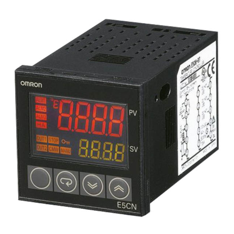
Nomenclature
E5CN
E5CN-U
The front panel is the same for the E5CN and E5CN-U.

Dimensions
Standard Models
E5CN
Terminal Models

Panel Cutout


- Recommended panel thickness is 1 to 5 mm.
- Group mounting is not possible in the vertical direction. (Maintain the specified mounting space between Controllers.)
- To mount the Controller so that it is waterproof, insert the waterproof packing onto the Controller.
- When two or more Controllers are mounted, make sure that the surrounding temperature does not exceed the allowable operating temperature specified in the specifications.
E5CN-U
Plug-in Models

Panel Cutout


- Recommended panel thickness is 1 to 5 mm.
- Group mounting is not possible in the vertical direction. (Maintain the specified mounting space between Controllers.)
- When two or more Controllers are mounted, make sure that the surrounding temperature does not exceed the allowable operating temperature specified in the specifications.
Accessories
Terminal Cover

Note: The suffix "500" is added to the model number of each Controller provided with a E53-COV10 Terminal Cover.
Current Transformers (Sold Separately)


E54-CT3 Accessory
- Armature
![]()

- Plug
![]()

Connection Example

Adapter
Note: Use this Adapter when the panel has already been prepared for the E5B .
.

E5CN-U Wiring Socket (Sold Separately)
Front-connecting Socket
P2CF-11


Note: A model with finger protection (P2CF-11-E) is also available.
Terminal Layout/Internal Connections (Top View)

Mounting Holes

Note: Can also be mounted to a DIN track.
Back-connecting Socket
P3GA-11

Note:
- Using any other sockets will adversely affect accuracy. Use only the specified sockets.
- A Protective Cover for finger protection (Y92A-48G) is also available.
Operation
Outline of Operation Procedures
The following diagram illustrates the entire setting level. A password is required to enter the advance function setting level and the calibration level.
Some parameters may not be displayed depending on the protection settings and operation conditions. The control operation will stop when switching from operation level to initial setting level.

Note:
- Operation level entered for software reset.
- You cannot move to other levels by operating the keys on the front panel from the calibration level. You must turn OFF the power supply.
- You can move only to the operation level by operating the keys on the front panel from the manual control level.
- The time taken to move to the protect level can be adjusted by changing the "Move to protect level time" setting.
Parameters
Some parameters are not displayed depending on the model of the Controller and parameter settings. For details, refer to the E5CN/E5CN-U Temperature Controller User's Manual (Cat. No. H129)


Improvements to E5CN Functionality
Changes
Model numbers have been changed to allow for multi-input specifications.

Precautions in Replacing Previous Controllers

- The input type setting numbers have changed to allow for multiinput specifications. (The default setting is for a K sensor between -200 and 1,300°C.)
- Previous E5CN Controllers cannot be removed from the case for replacement with new models. Replace the case at the same time.
- The previous ThermoTools cannot be used with the new Controller models. Use the ThermoTools scheduled for marketing from July 2004.
- The height of the front panel that extends when the Controller is mounted to a panel has been reduced from 9 to 6 mm.
Note: Items That Have Not Been Changed
- Panel cutout dimensions
- Panel interior dimensions for panel mounting
- Wiring terminal sizes
- Wiring terminal arrangement
- Parameter setting procedure
The following items do not change in comparison to the previous E5CN models: Panel cutout, Internal panel dimensions for panel mounting, wiring screw sizes, wiring terminal arrangement, and parameter setting methods.
Improved Functions
The previous and new models can be easily differentiated by looking at the front panel. The OMRON logo is in a different position.
| Item | Previous models (OMRON logo: lower left) | Improved models (OMRON logo: upper left) | ||
| Front panel |  |  | ||
Basically, the Controllers are upwardly compatible. The terminal arrangement, terminal sizes, and depth for panel mounting have not been changed. Changes are listed in the following tables. For details, refer to the E5CN/E5CN-U Temperature Controller User's Manual (Cat. No. H129) and to the E5CN Temperature Controller Communications User's Manual (Cat. No. H130).
Specifications
Ratings
| Item | Previous models | Improved models | |
| Power consumption | E5CN | 7 VA (100 to 240 VAC, 50/60 Hz) 4 VA/3 W (24 VAC, 50/60 Hz or 24 VDC) | 7.5 VA (100 to 240 VAC, 50/60 Hz) 4 VA/3 W (24 VAC, 50/60 Hz or 24 VDC) |
| E5CN-U | 6 VA (100 to 240 VAC, 50/60 Hz) 3 VA/2 W (24 VAC, 50/60 Hz or 24 VDC) | 6 VA (100 to 240 VAC, 50/60 Hz) 3 VA/2 W (24 VAC, 50/60 Hz or 24 VDC) | |
| Sensor input | E5CN-@@TC Thermocouple: K, J, T, E, L, U, N, R, S, or B Infrared temperature sensor: 10 to 70C, 60 to 120C or 115 to 165C (160 to 260C) Voltage input: 0 to 50 mV | E5CN-@@T (Multi-input models) Thermocouple: K, J, T, E, L, U, N, R, S, or B Infrared temperature sensor: 10 to 70C, 60 to 120C or 115 to 165C (160 to 260C) Voltage input: 0 to 50 mV Platinum resistance thermometer: Pt100 or JPt100 | |
| E5CN-@@P Platinum resistance thermometer: Pt100 or JPt100 | |||
| (No models with analog inputs) | E5CN-@@L (Models with analog inputs added.) Current input: 4 to 20 mA or 0 to 20 mA Voltage input: 1 to 5 V, 0 to 5 V, or 0 to 10 V | ||
| Control output | Relay | E5CN-R@@ SPST-NO, 250 VAC, 3 A (resistive load) Electrical life: 100,000 operations min. | E5CN-R@@ SPST-NO, 250 VAC, 3 A (resistive load) Electrical life: 100,000 operations min. |
| --- | E5CN-Y@@ (Added models with long-life relay outputs.) (To be available soon) SPST-NO, 250 VAC, 3 A (resistive load) Electrical life: 1,000,000 operations min. DC loads cannot be connected. | ||
| Voltage | E5CN-Q@@ 12 VDC 15% (PNP) Max. load current: 21 mA With short-circuit protection | E5CN-Q@@ 12 VDC 15% (PNP) Max. load current: 21 mA With short-circuit protection | |
| Current | E5CN-C@@ 4 to 20 mA DC Load: 600 max. Resolution: Approx. 2,600 | E5CN-C@@ 4 to 20 mA DC or 0 to 20 mA DC Load: 600 max. Resolution: Approx. 2,700 | |
| Control output 2 | Voltage | (No models with two control outputs) | (Option Unit) 12 VDC 15% (PNP) Max. load current: 21 mA With short-circuit protection |
| Display method | 7-segment digital display and single-LED indicators Character height: PV: 9.9 mm, SV: 6.4 mm | 11-segment digital display and single-LED indicator (Improved visibility) (A 7-segment digital display also possible.) Character height: PV: 11.0 mm, SV: 6.5 mm | |
| Transfer output | (No models with transfer outputs) | E5CN-C@@ (current output) Allocated to current output 4 to 20 mA DC or 0 to 20 mA DC Load: 600 max. Resolution: Approx. 2,700 | |
Other Functions
| Item | Previous models | Improved models |
| Display | --- | Parameter mask function (provided with setting software) |
| PV display switch between 2 colors (red/green) | PV display switch between 3 colors (red/orange/green) | |
| --- | Display character switch (7-segment/11-segment) | |
| Input | Temperature input shift (1-point shift for temperature input, 2-point shift for no-contact sensor input) | Temperature input shift (2-point shift also possible for temperature input) |
| Output | --- | Manual outputs |
| --- | MV at stop | |
| --- | MV at PV error | |
| --- | Loop break alarm | |
| Control | Control period: 1 to 99 s | Control period: 0.5 or 1 to 99 s |
| --- | Robust tuning | |
| Alarm | --- | Alarm delays |
| --- | Alarm SP selection (selection of alarm operation of SP indicator) | |
| Other | --- | Simple programming function |
| --- | Password to move to protect level | |
| --- | Setting software port |
Characteristics
| Item | Previous models | Improved models |
| Sampling period | 500 ms | 250 ms |
Communications Specifications
| Item | Previous models | Improved models |
| Communications protocols | CompoWay/F (SYSWAY) | CompoWay/F (SYSWAY), Modbus |
| Baud rate | 1200, 2400, 4800, 9600, 19200 bps | 1200, 2400, 4800, 9600, 19200, 38400 bps |
Heater Burnout/SSR Failure Detection Characteristics
| Item | Previous models | Improved models |
| Maximum heater current | Option Units Single-phase 50 A VAC | Option Units Single-phase 50 A AC |
| --- | Option Units (two CT inputs) Three-phase 50 A AC | |
| SSR failure detection | --- | SSR failure detection |
Precautions
Note: Refer to the ntlp: Electronic Temperature Controller Catalog (Cat. No. ntlp) for common precautions.

 Do not touch any of the terminals while the power is being supplied. Doing so may occasionally result in minor electric shock.
Do not allow pieces of metal or wire cuttings to get inside the Temperature Controller. Failure to do so may occasionally result in minor electric shock, fire, or damage to equipment.

Do not use the Temperature Controller in locations subject to flammable or explosive gas. Doing so may occasionally result in minor injury due to explosion.
Do not attempt to disassemble, modify, or repair the Temperature Controller or touch any internal components. Doing so may occasionally result in minor electric shock, fire, or damage to equipment.


Danger of Electric Shock
- This Temperature Controller is UL-listed as an open-type process controller. Use it in a control panel structure so that fire will not leave the panel.
- When using two or more cutoff switches, turn OFF all switches so that no power is supplied to the Temperature Controller before maintenance or inspections.
- Signal inputs are SELV restricted circuits. (See note 1.)
![]()
To reduce the danger of fire or electric shock, do not internally connect the outputs of different class 2 circuits. (See note 2.)
 If the output relay is used beyond its life expectancy, its contacts may occasionally become fused or burned. Always consider the actual application conditions and be sure to use the output relay within its rated load and electrical life expectancy. The life expectancy of the output relay varies considerably according to its switching capacity and operating conditions.
 Fire may occasionally occur if terminal screws become loose. Tighten the terminal screws using a torque between 0.74 and 0.90 N·m.
Make settings for the Temperature Controller that are suitable for the controlled system. Failure to do so may result in unexpected operation occasionally resulting in damage to equipment or personal injury.

To reduce the danger or electric shock or fire, use the Temperature Controller in an controlled environment relatively free from polluting materials.
Take appropriate safety measures, such as installing a separate monitoring system, to ensure safe operation in the event of a malfunction of the Temperature Controller. Loss of operation control or alarm outputs due to malfunction may occasionally result in physical damage to the controlled system or equipment.
Note:
- An SELV circuit is one separated from the power supply with double insulation or reinforced insulation, that does not exceed 30 V r.m.s. and 42.4 V peak or 60 VDC.
- A class 2 power supply is one tested and certified by UL as have the current and voltage of the secondary output restricted to specific levels.
Precautions for Safe Use
- Do not use the Temperature Controller in the following locations.
- Locations exposed to radiated heat from heating devices
- Locations subject to exposure to water or oil
- Locations subject to direct sunlight
- Locations subject to dust or corrosive gas (especially sulfide gas or ammonia gas).
- Locations subject to severe temperature changes
- Locations subject to icing or condensation
- Locations subject vibration or strong shock
- Use and store the Temperature Controller within the rated ambient temperature and humidity. When two or more Temperature Controllers are mounted horizontally close to each other or vertically next to one another, the internal temperature will increase due to heat radiated by the Temperature Controllers and the service life will decrease. In such a case, use forced cooling by fans or other means of air ventilation to cool down the Temperature Controllers.
- Allow enough space around the Temperature Controller to ensure proper heat dissipation. Do not block the ventilating holes.
- Be sure to wire terminals properly using the correct polarity.
- Use crimp terminals with the specified dimensions (M3.5, width 7.2 mm max.).
Use wires of a thickness of AWG24 (0.205 mm2) to AWG14 (2.081 mm2). The exposed current-carrying part to be inserted into terminals must be 5 to 6 mm. - Do not connect anything to unused terminals.
- Allow as much space as possible between the Controller and devices that generate powerful high frequencies (high-frequency welders, high-frequency sewing machines, etc.) or surge. Keep the wiring for the Temperature Controller's terminal block away from power cables carry high voltages or large currents. Also, do not wire power lines together with or parallel to Temperature Controller wiring.
- Use the Temperature Controller within a power supply voltage and load that meet all specifications and ratings.
- Set up the power supply so that the voltage will reach the rated voltage within 2 seconds after turning ON.
- Allow at least 30 minutes for the Temperature Controller to warm up.
- When using self-tuning, turn ON power for the load (e.g., heater) at the same time as or before supplying power to the Temperature Controller.
- Install the appropriate switches and circuit breakers and label them accordingly so that power can be turned OFF in an emergency by the person operating the Temperature Controller.
- If you remove the Controller from its case, do not touch or apply shock to the electronic parts inside. When placing the Controller back in the case, make sure that electronic parts do not come in contact with the case.
- Use alcohol to clean the Temperature Controller. Do not use thinner or other solvent-based substances.
- It will require 2 seconds for the outputs from the Temperature Controller to stabilize after turning ON the power supply. Design the system (e.g., the control panel) to allow for this time.
- Outputs will turn OFF depending on the mode when switching to the initial setting mode. Confirm system safety before switching the mode.
Precautions for Correct Use
Service Life
- Use the Temperature Controller within the following temperature and humidity ranges:
Temperature: 10 to 55C (with no icing or condensation)
Humidity: 25% to 85%
If the Controller is installed inside a control board, the ambient temperature must be kept to under 55C, including the temperature around the Controller. - The service life of electronic devices like Temperature Controllers is determined not only by the number of times the relay is switched but also by the service life of internal electronic components. Component service life is affected by the ambient temperature: the higher the temperature, the shorter the service life and, the lower the temperature, the longer the service life. Therefore, the service life can be extended by lowering the temperature of the Temperature Controller.
- When two or more Temperature Controllers are mounted horizontally close to each other or vertically next to one another, the internal temperature will increase due to heat radiated by the Temperature Controllers and the service life will decrease. In such a case, use forced cooling by fans or other means of air ventilation to cool down the Temperature Controllers. When providing forced cooling, however, be careful not to cool down the terminals sections alone to avoid measurement errors.
Measurement Accuracy
- When extending or connecting the thermocouple lead wire, be sure to use compensating wires that match the thermocouple types.
- When extending or connecting the lead wire of the platinum resistance thermometer, be sure to use wires that have low resistance and keep the resistance of the three lead wires the same.
- Mount the Temperature Controller so that it is horizontally level.
- If the measurement accuracy is low, check to see if input shift has been set correctly.
Waterproofing
The degree of protection is as shown below. Sections without any specification on their degree of protection or those with IP@0 are not waterproof.
Front panel: NEMA4X for indoor use (equivalent to IP66)
Rear case: IP20, Terminal section: IP00
(E5CN-U: Front panel: Equivalent to IP50, rear case: IP20, terminals: IP00)
Operating Precautions
- It takes approximately two seconds for the outputs to turn ON from after the power supply is turned ON. Due consideration must be given to this time when incorporating Temperature Controllers in a sequence circuit.
- When using self-tuning, turn ON power for the load (e.g., heater) at the same time as or before supplying power to the Temperature Controller. If power is turned ON for the Temperature Controller before turning ON power for the load, self-tuning will not be performed properly and optimum control will not be achieved.
- When starting operation after the Temperature Controller has warmed up, turn OFF the power and then turn it ON again at the same time as turning ON power for the load. (Instead of turning the Temperature Controller OFF and ON again, switching from STOP mode to RUN mode can also be used.) Avoid using the Controller in places near a radio, television set, or wireless installing.
- These devices can cause radio disturbances which adversely affect the performance of the Controller.
Mounting

Mounting to a Panel
- To mount the Controller so that it is waterproof, insert the waterproof packing onto the Controller. Group mounting does not allow waterproofing. The waterproof packing is not required if waterproofing is not necessary.
The Panel Mounting Adapter is also included with the E5CN-U. Waterproof packing is not included with the E5CN-U. - Insert the E5CN/E5CN-U into the mounting hole in the panel.
- Push the adapter along the Controller body from the terminals up to the panel, and fasten it temporarily.
- Tighten the two fixing screws on the adapter. Alternately tighten the two screws a little at time to keep them balanced. Tighten them to a torque of 0.29 to 0.39 N·m.
Attaching the Terminal Cover
Make sure that the "UP" letters on the E5CN are at the top and insert the terminal cover into the holes at the top and bottom of the Controller.
Removing the Controller from the Case
When carrying out maintenance on the Controller, the Controller can be removed from the case with the terminal leads still attached. The Controller can be removed from the case only with the E5CN. It cannot be removed with the E5CN-U.

- Insert the tool into the slots (one on the top and one on the bottom) and release the hooks.
- Insert the tool into the gap between the front panel and rear case and pull out the front panel slightly. Hold both sides of the front panel and draw out the Controller towards you. Do not apply unnecessary force.
- Before inserting the Controller, confirm that the sealing rubber is in place. Insert the Controller into the rear case until you hear a click. Press on the hooks on the top and bottom of the rear case to be sure that the hooks are securely locked in place. Be sure that electronic parts do not come in contact with the case.
Wiring Precautions

- Separate input leads and power lines to protect the Controller and its lines from external noise.
- Use wires of a thickness of AWG24 (0.205 mm2) to AWG14 (2.081 mm2).
The exposed current-carrying part to be inserted into terminals must be 5 to 6 mm. - We recommend using crimp terminals when wiring the terminals.
- Tighten terminal screws to a torque of 0.74 to 0.90 N·m.
- Use the following type of crimp terminals for M3.5 screws.
Documents / ResourcesDownload manual
Here you can download full pdf version of manual, it may contain additional safety instructions, warranty information, FCC rules, etc.
Download Omron E5CN, E5CN-U, E5CN-RMT-500, E5CN-QMT-500, E5CN-CMT-500 Manual
Advertisement


Need help?
Do you have a question about the E5CN and is the answer not in the manual?
Questions and answers