Advertisement
Quick Links
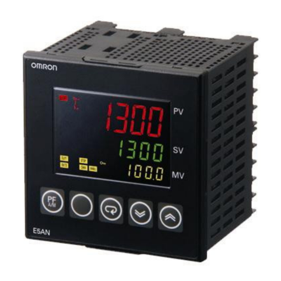
Temperature
Controllers
E5□N
Simplicity on the Worksite
Solutions Guide for FAQs
Basic Setup Procedure
Connect sensor and operating terminal.
Turn ON power.
1. Setting the sensor type
2. Using ON/OFF control
Setting the set point
4. Setting temperature alarms
Digital Temperature Controllers
Basic Type
START
3. Using PID control
5. Setting heater
burnout alarms
Operation
CONTENTS
1. Setting the Sensor Type
2. Using ON/OFF Control
3. Using PID Control
4. Setting Temperature Alarms
5. Setting Heater Burnout
Alarms
Advertisement

Related Manuals for Omron E5*N Series


Summary of Contents for Omron E5*N Series
- Page 1 Temperature Digital Temperature Controllers Basic Type Controllers E5□N Simplicity on the Worksite Solutions Guide for FAQs Basic Setup Procedure CONTENTS START 1. Setting the Sensor Type Connect sensor and operating terminal. 2. Using ON/OFF Control Turn ON power. 3. Using PID Control 4.
- Page 2 OMRON. No patent liability is assumed with respect to the use of the information contained herein. Moreover, because OMRON is constantly striving to improve its high-quality products, the information contained in this manual is subject to change without notice.
- Page 3 Simplicity on the Worksite Solutions Guide for FAQs: E5@N Setting the Sensor Type Setting the Sensor Type Select and set the sensor type (i.e., the Input Type parameter) to the set value that corresponds to the type of sensor used in the application and the required temperature range. The parameter is set to 5 (K thermocouple at −200 to 1,300 °C) by default.
- Page 4 Simplicity on the Worksite Solutions Guide for FAQs: E5@N Setting the Sensor Type Setting the Sensor Type You set this parameter in the Initial Setting Level. The parameter is set to 5 (K thermocouple at −200 to 1,300 °C) by default. Turn ON the power supply.
- Page 5 Simplicity on the Worksite Solutions Guide for FAQs: E5@N Using ON/OFF Control Using ON/OFF Control The procedure to use ON/OFF control is given step by step in this section. Step 1 Determining the Control Method Select direct or reverse operation. The default setting is for reverse operation.
- Page 6 Simplicity on the Worksite Solutions Guide for FAQs: E5@N Using ON/OFF Control Step 2 Setting ON/OFF Control Parameters Setting ON/OFF Control You set this parameter in the Initial Setting Level. The parameter is set to ON/OFF control by default. Turn ON the power supply. Operating Display Press the Key for at least 3 seconds.
- Page 7 Simplicity on the Worksite Solutions Guide for FAQs: E5@N Using ON/OFF Control Setting the Hysteresis You set this parameter in the Adjustment Level. The parameter is set to 1.0°C by default. Turn ON the power supply. Operating Display Adjustment Level ←l.adj (L.ADJ) will be displayed to show that the Adjustment Press the...
- Page 8 Simplicity on the Worksite Solutions Guide for FAQs: E5@N Using ON/OFF Control MEMO...
- Page 9 Simplicity on the Worksite Solutions Guide for FAQs: E5@N Using PID Control Using PID Control The procedure to use PID control is given step by step in this section. Step 1 Determining the Control Method Select direct or reverse operation. The default setting is for reverse operation.
- Page 10 Simplicity on the Worksite Solutions Guide for FAQs: E5@N Using PID Control Step 2 Setting PID Control Parameters Setting PID Control You set this parameter in the Initial Setting Level. The parameter is set to ON/OFF control by default. Turn ON the power supply. Press the Key for at least 3 seconds.
- Page 11 Simplicity on the Worksite Solutions Guide for FAQs: E5@N Using PID Control Setting direct or reverse operation. You set this parameter in the Initial Setting Level. The parameter is set to reverse operation by default. Change the parameter with the Key.
- Page 12 Simplicity on the Worksite Solutions Guide for FAQs: E5@N Using PID Control Executing Autotuning Turn ON the power supply. Operating Display Adjustment Level ←l.adj(L.ADJ) will be displayed to show that the Adjustment Level Press the has been entered. (Level) Key for less than 1 second.
- Page 13 Simplicity on the Worksite Solutions Guide for FAQs: E5@N Using PID Control Setting PID Constants Manually You set the PID constants manually in the Adjustment Level. The default settings of the PID constants are as follows: P (proportional band) = 8.0°C, I (integral time) = 233 seconds, D (derivative time) = 40 seconds.
- Page 14 Simplicity on the Worksite Solutions Guide for FAQs: E5@N Using PID Control Reference Information: PID Control Problems with 100% Autotuning (AT-2) If autotuning at 100% (AT-2) does not produce the desired results, you can also execute autotuning at 40% (AT-1). ●Autotuning at 40% (AT-1) A 40% variation in the manipulated variable of the limit cycle is used for autotuning.
- Page 15 Simplicity on the Worksite Solutions Guide for FAQs: E5@N Setting Temperature Alarms Setting Temperature Alarms The procedure to set temperature alarms is given step by step in this section. Step 1 Determining the Alarm Set Value Selecting the Alarm Type How To Select an Alarm Type E5@N Consider the following three points and select the alarm type...
- Page 16 Simplicity on the Worksite Solutions Guide for FAQs: E5@N Setting Temperature Alarms Select from the table on page 4-3. ●Alarm linked to the set point If the set point is changed, the set Do you need to value of the alarm will also change. link the alarm Set this difference.
- Page 17 Simplicity on the Worksite Solutions Guide for FAQs: E5@N Setting Temperature Alarms Available Alarm Types You select the alarm type according to the required conditions. Alarm Type Do you want Operation In what Name to link the Do you need cases do Set this number in the Temperature alarm...
- Page 18 Simplicity on the Worksite Solutions Guide for FAQs: E5@N Setting Temperature Alarms Alarm Type Do you want Operation In what Name to link the Do you need cases do Set this number in the Temperature alarm a standby you want to Controller temperature sequence?
- Page 19 Simplicity on the Worksite Solutions Guide for FAQs: E5@N Setting Temperature Alarms Determining the Alarm Value What Value Is Set for an Alarm? You set the temperature at which the alarm is output. There are two methods to set the temperature for the alarm types selected on pages 4-3 and 4-4: a deviation or an absolute temperature.
- Page 20 Simplicity on the Worksite Solutions Guide for FAQs: E5@N Setting Temperature Alarms Step 2 Setting Alarm Parameters Setting the Alarm Type You set this parameter in the Initial Setting Level. The parameter is set to 2 (Upper-limit Alarm) by default. Turn ON the power supply.
- Page 21 Simplicity on the Worksite Solutions Guide for FAQs: E5@N Setting Temperature Alarms Setting the Alarm Value You set the alarm value in the Operation Level. The following procedure continues on from the procedure to set the Alarm Type parameter (Initial Start here if you just turned Setting Level).
- Page 22 Simplicity on the Worksite Solutions Guide for FAQs: E5@N Setting Temperature Alarms Set the alarm value with the Keys. Setting Alarm Type 2, 3, 6, 7, 8, 9,10, or Setting Alarm Type 1, 4, or 5 (Upper-limit and (Upper-limit Alarms and Lower-limit Lower-limit Alarms or Upper-limit and Lower-limit Alarms) Range Alarms)
- Page 23 Simplicity on the Worksite Solutions Guide for FAQs: E5@N Setting Temperature Alarms Step 3 Additional Settings as Required Determining the Alarm Hysteresis (Deviation between ON and OFF) What Is Alarm Hysteresis? The alarm hysteresis is the difference between the temperature where the alarm output turns ON and the temperature where it turns OFF.
- Page 24 Simplicity on the Worksite Solutions Guide for FAQs: E5@N Setting Temperature Alarms Setting the Hysteresis You set this parameter in the Initial Setting Level. The parameter is set to 0.2°C by default. Turn ON the power supply. Operating Display Press the Key for at least 3 seconds.
- Page 25 Simplicity on the Worksite Solutions Guide for FAQs: E5@N Setting Temperature Alarms Reference Information: Other Related Settings Reversing Outputs You can reverse the status of an auxiliary output (alarm output) before it is actually output. With the default setting, the output will be ON when the alarm is ON and OFF when the alarm is OFF (NO: Close in Alarm).
- Page 26 Simplicity on the Worksite Solutions Guide for FAQs: E5@N Setting Temperature Alarms Alarm Latch You set a latch for an alarm output. If an alarm latch is enabled, the alarm, once it turns ON, will remain ON regardless of the present temperature until it is cleared by turning OFF the power, pressing the PF Key, or using an event input.
- Page 27 Simplicity on the Worksite Solutions Guide for FAQs: E5@N Setting Temperature Alarms Alarm ON Delay and Alarm OFF Delay Alarm ON Delay: You can delay the time when the output actually turns ON from when the alarm status turns ON. Alarm OFF Delay: You can delay the time when the output actually turns OFF from when the alarm status turns OFF.
- Page 28 Simplicity on the Worksite Solutions Guide for FAQs: E5@N Setting Temperature Alarms Alarm Parameter Setting Levels 4-14...
- Page 29 Simplicity on the Worksite Solutions Guide for FAQs: E5@N Setting Heater Burnout Alarms Setting Heater Burnout Alarms The procedure to output heater burnout alarms is given step by step in this section. A heater burnout alarm operates by detecting the heater current with a current transformer (CT). If the detected current is less than the specified heater burnout detection current even though the control output is ON, a heater burnout will be assumed and an alarm will be output.
- Page 30 Simplicity on the Worksite Solutions Guide for FAQs: E5@N Setting Heater Burnout Alarms Set the heater current to treat as a heater burnout. Set the Heater Burnout Detection 1 parameter in the Adjustment Level to the heater current to treat as a heater burnout.
- Page 31 MEMO...
- Page 32 The Netherlands IL 60173-5302 U.S.A. Tel: (31)2356-81-300/Fax: (31)2356-81-388 Tel: (1) 847-843-7900/Fax: (1) 847-843-7787 © OMRON Corporation 2010 All Rights Reserved. OMRON (CHINA) CO., LTD. OMRON ASIA PACIFIC PTE. LTD. In the interest of product improvement, Room 2211, Bank of China Tower, No.
Need help?
Do you have a question about the E5*N Series and is the answer not in the manual?
Questions and answers