Advertisement
- 1 About this manual
- 2 Introduction
- 3 How Wavetable synthesis works
- 4 Working with transients
- 5 Preset Wavetables and Transients
- 6 Modulation Matrix
-
7
Top Panel
- 7.1 Master Controls
- 7.2 Low Frequency Oscillator
- 7.3 Envelope Generator 1
- 7.4 Modifiers
- 7.5 Filter Modulation
- 7.6 Waves Modulation
- 7.7 Envelope Generator 3
- 7.8 Envelope Generator 2
- 7.9 Loudness modulation
- 7.10 Group
- 7.11 Modifiers Control
- 7.12 Display
- 7.13 Numeric Keypad
- 7.14 Display/Menu Select and Sequencer Controls
- 7.15 Performance Controls
- 8 Menus
- 9 Using The Sequencer
- 10 User Waves and Transients
- 11 Programs
- 12 Rear Panel
- 13 Calibration
- 14 MIDI CCs
- 15 MIDI NRPNs
- 16 SysEx
- 17 Troubleshooting
- 18 Glossary
- 19 SynthTribe
- 20 Important Safety Instructions
- 21 Documents / Resources
About this manual
This manual offers a comprehensive guide to the Wave synthesizer, detailing its functionality and features. Additionally, it includes a brief introduction to wavetable synthesis, providing insight into the theory behind this synthesis method. We highly recommend reading through this manual to fully acquaint yourself with the controls and enhance your experience with the instrument.
Introduction
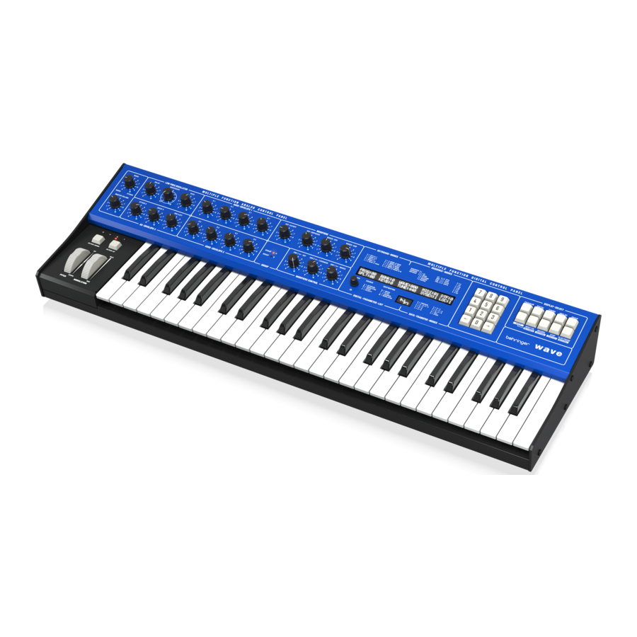
The Wave is an 8-voice hybrid wavetable synthesizer that combines digital and analog sound generation techniques to deliver rich and complex sounds. Unlike conventional analog synthesizers that rely on voltage-controlled oscillators, The Wave employs digitally crafted waveforms housed in wavetables for sound generation. Each voice in this system is composed of a pair of oscillators, the main and the sub. These oscillators are combined and then transformed into analog signals via a Digital-to-Analog Converter (DAC). Following this conversion, the signal is directed through a Voltage-Controlled Filter (VCF) and a Voltage Controlled Amplifier (VCA), completing the sound production process.
")
To further enhance sound design capabilities, the Wave includes a comprehensive modulation matrix, three envelope generators, and a low-frequency oscillator with four waveforms and adjustable delay. Creative possibilities are expanded with an extensive set of keyboard modes and split points, allowing the synth to be used in standard 8-voice polyphony, unison, or bi-timbral configurations with a layered keyboard.
The Wave offers 30 factory wavetables and 64 user-defined wavetables, each containing 64 waveforms. Additionally, there are 32 slots available for user-defined transients. Both user-defined wavetables and transients can be downloaded using the SynthTribe app.
How Wavetable synthesis works
Wavetable synthesis is a digital sound generation technique based on the periodic reproduction of single-cycle waveforms. Introduced for the first time in the eighties and pioneered by artists such as Depeche Mode, Tangerine Dream and Tears for Fears, wavetable synthesis is widely used today by musicians and sound designers for the versatility it offers. In a wavetable synthesizer, singlecycle waveforms are stored in tables called wavetables. What sets wavetable synthesis apart from other generation techniques is the ability to sweep through the wavetable, generating complex, evolving sounds. Like any other modulation destination, wavetable sweeping can be controlled by various modulation sources such as envelopes and LFOs, expanding the sonic possibilities. The image graphically depicts how the output sound changes when sweeping the wavetable using a four-stage ADSR envelope. For the sake of simplicity, a wavetable with four waveforms is considered.

When transitioning from one waveform to the next, artifacts can be generated due to phase discontinuities between waveforms resulting in abrupt transitions. This characteristic is typical of the first wavetable synthesizers and contributes to their distinctive sound. The Wave offers the option to reduce these artifacts through the Osc setting in the User menu. With this setting engaged, the adjacent waveforms are morphed together resulting in smoother transitions.
Each of the Wave synthesizer wavetables contains 64 single cycle waveforms. In each wavetable the last four waveforms emulate the typical analog waveforms: Sawtooth, pulse, square and triangle. In addition to the envelope, the waveform position can be further modulated by many sources including the LFO, Aftertouch, Modulation wheel, Pitch wheel, expression pedal and keyboard, further extending the expressiveness of the instrument. The Wave also offers the possibility to store and reproduce up to 32 transient sounds, adding to its sonic capabilities.
Each voice consists of two independent oscillators, one main oscillator and a secondary sub oscillator. The position of each oscillator inside the wavetable can be controlled using the Waves-Osc and Waves-Sub controls. When sweeping through the wavetable the sub oscillator waveform can be set to run in parallel with the main oscillator or to be manually controlled.
In addition to the wavetable selected from the Program menu, each program has an additional wavetable called the Upper wavetable, which can be enabled via the UW option in the Digital menu. These two wavetables are linked in a looping sequence, meaning that when any modulation source exceeds the wavetable lower or upper limits, the upper wavetable will become audible.
Working with transients
The Wave also supports transient sounds, which are short audio samples you can import using the SynthTribe app. When a transient slot is selected from the Program menu, the WAVE text is replaced with TRAN. In this mode, WavesOsc and Waves-Sub set the start points for the main and sub oscillators, while ENV1>WAVES sets the loop point for both oscillators. The loop size is fixed to 128 samples. For information on how to import custom transients, please refer to the section "User Waves and Transients".

Preset Wavetables and Transients
As mentioned in the introduction the Wave comes with 30 preset wavetables and one preset transient. In addition to this a number of the user defined slots have wavetables in them from the factory, which can be overwritten if required.
The preset wavetables are:

The Wave is shipped with additional wavetables in slots 64 – 83, which can be over-written using SynthTribe:
| No | Name | Description |
| 64 | Pipes Xfade | Crossfade of two Church Organ Pipe Waveforms |
| 65 | PD_Saw PWM | SAW Waveshaper |
| 66 | DX_Tubular | Famous DX Tubular sound |
| 67 | DX_E.Guitar | Jazz Guitar |
| 68 | DX_FullTine | Famous Full Tines Sound |
| 69 | Vibe-rant | Vibraphone Waveforms |
| 70 | DX_Bass | Digital Bass |
| 71 | StratoSweep | Corssfade of four digital synth waveforms |
| 72 | FormantPad | Rotating Phase Shifter |
| 73 | FairVox | Famous Fairlight Voices |
| 74 | SpaceSweep | Famous D50 Synth Sound |
| 75 | SoundTrack | LA Filter Sweep |
| 76 | PWMstringer | SAW+PWM_Square+Sub Juno Sound |
| 77 | Hoover | Juno 106 PWM |
| 78 | PD_Saw | CZ Phase Distortion SAW |
| 79 | PD_SQU | CZ Phase Distortion SQU |
| 80 | PD_TPL | CZ Phase Distortion TRI Pulse |
| 81 | PD_DBL | CZ Phase Distortion Double Sine |
| 82 | PD_SPL | CZ Phase Distortion Sine Pulse |
| 83 | PD_RES | CZ Phase Distortion Resonant |
| 84 | Wurli Wave | Electric Reed Piano |
| 85 | Rhodos | Electric Piano |
| 86 | Vorcode | Vocal Jam |
The preset transients are:
| No | Name | Description |
| 31 | PianoSaxo | Piano and Saxophone Sample |
| 32 | PanFlute | Wood Flute |
| 33 | Pizzi | String Section Pizzicato |
| 34 | Steel Guitar | Plugged Steel String |
| 35 | Elec. Cello | PM Solo String Sound |
| 36 | Xylophon | Xylophone with hard Mallet |
| 37 | Harp | Plugged Harp String |
| 38 | Pizzagogo | Famous D50 Sound |
| 39 | Soft Bell EP | PM Electric Piano |
| 40 | Medium EP | Medium Velocity EP Tone |
| 41 | Trumpet | Solo Trumpet Tone |
| 42 | Mute Trumpet | Muted Trumprt Tone |
| 43 | Duuhh | Scat Voices |
 Note that transients 32 – 38 can be over-written using SynthTribe.
Modulation Matrix
The Wave synthesizer offers a wide range of modulation options, providing the user with virtually infinite capabilities in terms of sound design. MAIN-OSC and SUB-OSC pitch, Waves, VCF, and VCA can be modulated through various settings accessible in the menus. The table below shows the modulation matrix. The types of modulation, and their options are discussed in Top Panel below; and in the Digital Menu section.
| Destination / Source | Pitch Bend | Mod Wheel(1) | LFO(2) | KEY | Velocity | AF(3) | Exp Ped(4) | ENV1 | ENV2 | ENV3 |
| MAIN-OSC PITCH | x | x | x | |||||||
| SUB-OSC PITCH | x | x | x | |||||||
| WAVES (MAIN and SUB) | x | x | x | x | x | x | x | x | ||
| Filter Cutoff | x | x | x | x | x | x | x | x | ||
| Loudness | x | x | x | x | x | x | ||||
| Filter emphasis | x | x |
(1) & (2) Modulation wheel can be either used as a direct source of modulation or to control the amount of modulation by the LFO.
(3) After touch must be enabled in the User menu (setting TOUCH).
(4) The Expression Pedal can be assigned to directly modulate these parameters. If it is set to EXP:5, it will have the same effect as turning the MOD wheel.
Top Panel

The following sections describe the top panel controls of the Wave; and how they are used in program creation. All Top Panel control settings are stored in the program memories, with the exception of Basis (1) and Master Volume (2). The control settings can be monitored and fine adjusted if needs be in the Analog Menu, described below.
Master Controls

 Basis – adjusts the stereo spread of the notes played on the keyboard. When the control is at minimum then all notes will be output at equal level from both the channel 1 and channel 2 outputs. When the control is at maximum notes will alternate between the outputs.
 Master Volume – sets the Wave's output level.
Low Frequency Oscillator

 LFO Delay – delays the action of the LFO. When the control is at minimum there will be a slight delay before modulation can be heard (depending on the firmware setting (see User Menu below)). When at maximum there will be a delay of 10 seconds before modulation is applied.
 Waveshape – the LFO has four waveshapes available: triangle, ramp, sawtooth and square.
 Rate – controls the rate at which the LFO runs, from 0.2 Hz to 12.0 Hz.
Envelope Generator 1

 EG 1 Attack – controls the attack time for the filter envelope. If the Envelope attack rate is set above 47 then the attack will fully complete even if the key is released; and will then move to the release phase. This can be used for filter and wavetable sweeps.
 EG 1 Decay – controls the decay time for the filter envelope.
 EG 1 Sustain – controls the sustain level for the filter envelope following Decay.
 EG 1 Release – controls the release time for the filter envelope.
Modifiers

 VCF Cutoff – controls the cutoff frequency of the low pass filter.
 VCF Emphasis – controls the resonance of the filter.
Each of the voices of the Wave synthesizer is equipped with a 24dB per octave voltage-controlled low-pass filter, based on the reproduction of the SSM2044 chip. The VCF-Cutoff knob sets the filter cutoff frequency: frequencies below this threshold pass unchanged, while frequencies above it are attenuated. Turning the VCF-Cutoff knob clockwise increases the cutoff frequency, so when the knob is turned fully clockwise, the sound passes unchanged. The Emphasis control adjusts the filter resonance, emphasizing the frequencies around the cutoff frequency set by the VCF-Cutoff knob. If the resonance is increased significantly, the filter will start to self-oscillate, generating a sine wave whose frequency depends on the VCF Cutoff. You can experiment the effect of the resonance by increasing the Emphasis knob. Setting the emphasis to values below 50%, produces the typical bright sound. Please note that one of the characteristics of the SSM2044 is the dependency between resonance and output signal level: as the resonance increases, the filter output level decreases. The operation of the filter is depicted in the image below.

Filter Modulation
Filter Cutoff frequency can be modulated by the following sources:
- Pitch bend (Option BD in Digital menu)
- Modulation Wheel (Option MF in Digital menu)
- Low Frequency Oscillator (Option MF in Digital menu)
- Keyboard (Option KF in Digital menu)
- Velocity (Option VF in Digital menu)
- Envelope 1 (Default)
- Expression Pedal (Option EXP-PED in USER menu)
- Channel Aftertouch (Option TL in Digital menu)

 Waves Osc – steps through the waveforms of the selected wavetable for the main oscillator, from 00 to 63.
 Waves Sub – steps through the waveforms of the selected wavetable for the sub oscillator, from 00 to 63.
If the selected waveform is a transient one (31-63) then controls (12) and (13) will set the sample playback start points for the main and sub oscillators.
Waves Modulation
Main and Sub oscillator waves can also be modulated by:
- Pitch bend (Option BD in Digital menu)
- Modulation wheel (Option MW in Digital menu)
- LFO (Option MW in Digital menu)
- Keyboard (Option KW in Digital menu)
- Aftertouch (Option TW in Digital menu)
- Expression pedal (Option EXP-PED in USER menu)
- Envelope 1 or Envelope 3 (Option SW in Digital menu)

Envelope Generator 3

 EG3 Attack – controls the attack time for the third envelope.
 EG3 Decay – controls the decay time for the third envelope.
 EG3 Attenuation – attenuates (reduces) the maximum output of the third envelope generator. This has a different effect according to what the third envelope is being used for: if it is being used on the pitch of the oscillator then in position five there is no modulation, with lower settings resulting in negative action and higher in positive. When used for modulating the wavetables then the settings run from no modulation at 0 to full (63 wavetable steps) at 10. This modulation is added to the WAVES SUB value.
Envelope Generator 2

 EG 2 Attack – controls the attack time for the loudness envelope. If the Envelope attack rate is set above 47 then the attack will fully complete even if the key is released; and will then move to the release phase. This can be used for filter and wavetable sweeps.
 EG 2 Decay – controls the decay time for the loudness envelope.
 EG 2 Sustain – controls the sustain level for the loudness envelope following Decay.
 EG 2 Release – controls the release time for the loudness envelope.
Loudness modulation
Loudness can be modulated by the following sources:
- LFO (Option ML in Digital menu)
- Keyboard (Option KL in Digital menu)
- Velocity (Option VL in Digital menu)
- Aftertouch (Option TL in Digital menu)
- Expression pedal (Option EXP-PED in USER menu)
- Envelope 2 (Default)

* TOUCH has bo ne enabled in the USER menu.
Note that the ML option set to 1 switches on direct modulation through the LFO if FIRM is 0. When FIRM is set to 1, then the amount of LFO loudness modulation is determined by the Mod wheel. See User Menu and Digital Menu sections below.
Group

 Group – each program has two sounds associated with it, in groups A and B.
The group LEDs indicate which sound can be edited when using the DIGITAL/ TUNING/ANALOG menus. If both LEDs are lit, parameter changes effect both group sounds. In KEYB POLY 8x1 mode, the lit LED indicates which sound is used. (if both LEDs are lit, group B sound is used).
Modifiers Control

 Env 1 VCF – controls the amount of filter modulation from Envelope Generator 1.
 Env 2 Loudness – this control adjusts the output level of the active group; and can be used to balance group A and B sounds when used together or in a split mode.
 Env 1 Waves – controls the use of Envelope Generator 1 to step through the waveforms in the wavetable in use. If a transient is selected then this control will set the loop point for sample playback for both the main oscillator and the sub-oscillator.
Display

 Data Control – used as an alternative to the keypad for entering values. Turn the control to the desired value then press to change the value.
 LCD Display – 2 x 40 character display, showing different parameter information according to which button on the keypad is in use. The display is vitally important when using the various menus.
 OLED Display – The OLED display serves as an oscilloscope, displaying the real-time output waveform of the synth. During calibration, it provides calibration information. It also shows the names of selected wavetables and transients when in editing mode and confirms successful receipt of wavetables or transients transferred via SynthTribe.
Numeric Keypad

 Numeric Keypad – used for direct number entry and cursor control.
Display/Menu Select and Sequencer Controls

 Program – calls up the program menu to the display. This is the default menu on power-up. Pressing the button twice calls up the User menu. See Program and User Menus below for full detail.
 Digital – calls up the digital parameters to the display for editing. See Digital menu below for full detail.
 Tuning – calls up the tuning parameters to the display for editing. See Tuning menu below for full detail.
 Analog – calls up the analog parameters to the display for editing. See Analog menu below for full detail.
 Group – each program has two sounds associated with it, in groups A and B.
The group LEDs indicate which sound can be edited when using the DIGITAL/ TUNING/ANALOG menus. If both LEDs are lit, parameter changes effect both group sounds. In KEYB POLY 8x1 mode, the lit LED indicates which sound is used. (if both LEDs are lit, group B sound is used).
SEQUENCER BUTTONS
 Shift – used to access the shifted functions on buttons 35 - 38.
 Rest/Tie – pressing this button while holding a note or chord will extend (tie) the note(s) across more than one step of the sequence. Pressing it without holding any notes will insert a rest at that point in the sequence.
 Record – puts the sequencer into Record mode.
 Stop – when a sequence is running pressing the stop button stops the sequence and resets it to the first position.
 Play/Pause – if a sequence is not running then pressing this button starts it. A further press will pause the sequence, but unlike the use of the Stop button will not reset to first position. Pressing the button a third time will restart the sequence from the point that it was paused.
Using the Shift button with the four sequencer buttons adds additional functions:
Shift & 35 – Settings – accesses sequencer settings menu. See Sequencer Menu below for full detail.
Shift & 36 – Append – after using the </> buttons to go to a specific step in the sequence pressing Shift and 36 allows you to add additional notes to those already recorded on the selected step, to the maximum allowed by the keyboard settings; or to replace the already programmed note(s), depending on the OVP settings in the Sequencer menu.
Shift & 37 – Clr Lst – Clear Last allows steps to be erased from the sequence, starting with the last step recorded. Pressing and holding Clear Last will erase the whole sequence.
Shift & 38 – Restart – when a sequence is running pressing Shift and 38 restarts it from the first step.
Performance Controls

 Pitch Wheel – the function of the Pitch Wheel is configured through the BD option in the Digital menu. It can operate as a traditional pitch bend controller for one or both oscillators or be assigned to control other parameters, such as filter cutoff or wavetable position. The wheel automatically returns to its center position when released.
Main and Sub Oscillator Modulation
Both the Main and Sub oscillators' pitch can be modulated by the following sources:
- Pitch bend (Option BD in Digital menu)
- LFO (Option MO and SO in Tuning menu, through the MOD wheel)
- Expression pedal (Option EXP-PED:5 in USER menu, through the LFO if MO/SO is activated)
- Envelope 3 (Option EO and ES in Tuning menu)
Note: Bend Interval (BI) in Digital menu determines amount of Pitch Wheel modulation. EO2 - 9 in TUNING menu activates polyphonic portamento.

 Modulation Wheel – can be used for various types of modulation depending on the user settings. Please note that the wheel position is stored in each preset, separate for Group A and B sound parameters.
 Octave Up/Down – transposes the keyboard up by one octave or down by one or two octaves, as indicated by the associated LEDs.
Menus
Program Menu

This is the default menu, which you will see on the display when you power up. It indicates the status of the Wave.
Please note that where two characters are required on a data entry then a leading zero should be added for single figure numbers (eg 01 for 1.) Parameters are navigated using the left and right cursor controls on the numeric keypad ; or by using the data encoder .
From left to right / top row:
PROG – indicates the current program number from 0 to 99.
BANK – indicates the program bank in use, 0 or 1.
WAVE/TRAN – indicates the wavetable or transient associated with the current program, from 0 to 127. Positions 0 to 30 are the preset wavetables, position 31 is a preset transient wave, positions 32 to 63 are user defined transients and positions 64 to 127 are user defined wavetables.
MIDI – indicates the MIDI transmit and receive channel that your Wave is set to.
0 – indicates that MIDI is switched off; no messages will be transmitted or received.
1-16 – indicates that the Wave will transmit and receive on the specified channel (MIDI mode 3).
DTF – indicates Data Transfer status as follows:
- Program (default)
- A – A, B – B: the program data for the group A sound is loaded into the group A edit buffer, and that of group B to the group B edit buffer. Wavetable, split and keyboard mode are unaffected.
- A – A: the program data for the group A sound is loaded into the group A edit buffer. Group B, wavetable, split and keyboard mode are unaffected.
- B – B: the program data for the group B sound is loaded into the group B edit buffer. Group A, wavetable, split and keyboard mode are unaffected.
- A – B: the program data for the group A sound is loaded into the group B edit buffer. Group A, wavetable, split and keyboard mode are unaffected.
- B – A: the program data for the group B sound is loaded into the group A edit buffer. Group B, wavetable, split and keyboard mode are unaffected.
- A – A & B: the program data for the group A sound is loaded into both edit buffers. Wavetable, split and keyboard mode are unaffected.
- B – A & B: the program data for the group B sound is loaded into both edit buffers. Wavetable, split and keyboard mode are unaffected.
- INIT: this option resets the Wave to its factory settings. You will be asked to type 1 to confirm reset or 0 to cancel.
- Store
To use the Data Transfer menu to store your edited programs take the following steps:
- Make your edits as required.
- Move the cursor in the program menu to DTF. The number next to the DTF indicator should be 0, which is the default setting.
- Press 9.
- Select the required program bank (0 or 1).
- Move the cursor to the PG (program) position and select the program number that you wish to write to, even if you are writing to the same program memory. You will be asked to confirm the write operation by typing 1 for yes or 0 for no. This completes the operation, and DTF will return to 0.
From left to right / bottom row:
SPLT – allows the programming of keyboard split point for use with keyboard modes 4 – 8 as discussed below. The lowest octave of the keyboard, in -2 octave mode, is represented by 0 – 12; -1 octave mode 13-24; 0 octave mode 25-36 etc.
The note selected as the split point will be the lowest note of the upper keyboard.
KEYB – indicates which keyboard mode is in use:
- Poly (default) – eight note polyphony with one oscillator voice and one sub-oscillator voice for each note, sound can be switched between Group A and Group B using button 34.
- Quad – four note polyphony with two oscillator voices and two suboscillator voices for each note, four voices each from Group A (odd numbers) and B (even numbers).
- Duo – duophonic operation with four oscillator voices and four suboscillator voices for each note, four voices each from Group A (odd numbers) and B (even numbers).
- Mono (Unison) – monophonic operation with all eight oscillator voices and eight sub-oscillator voices for each note, four voices each from Group A (odd numbers) and B (even numbers).
- A - Quad, B - Quad – split mode with four note polyphony for each sound in Group A and Group B, with Group A sounds on the upper keyboard and Group B on the lower.
- A – Mono, B – Quad – split mode where the Group A sound is monophonic with four oscillator voices and four sub-oscillator voices and the Group B sound is four note polyphonic with one oscillator voice and one sub-oscillator voice per note played, with Group A sounds on the upper keyboard and Group B on the lower.
- A – Mono, B – Poly – split mode where the Group A sound is monophonic with two oscillator and two sub-oscillator voices and the Group B sound is six note polyphonic with one oscillator voice and one sub-oscillator voice per note played, with Group A sounds on the upper keyboard and Group B on the lower.
- A – Poly, B – Mono – split mode where the Group A sound is six note polyphonic with one oscillator voice and one sub-oscillator voice per note played and group B is monophonic with two oscillator and two sub-oscillator voices, with Group A sounds on the upper keyboard and Group B on the lower.
- A – Mono, B – Mono – split mode where Group A and Group B are monophonic, with four oscillator voices and four sub-oscillator voices each, with group A sounds on the upper keyboard and group B on the lower.
- A – Poly, B – Mono CV IN – Group A sound is 7 notes polyphonic, monophonic Group B sound is controlled by CV/GATE Inputs on the rear panel
TUNE – indicates the master tuning of the Wave. Normally this would be set to
A = 440 (Hz), but it can be adjusted in the range 400 Hz to 499 Hz
SYSEX – Used for manual dump of program data. 0 – default (no action).
- sends current edit buffer data.
- sends current program data.
- sends current bank.
- sends sequencer edit buffer.
- sends current program's sequencer data.
- sends current bank's sequencer data.
LOC – selects whether local control from the internal keyboard is active, or whether the Wave will only respond to incoming MIDI messages:
0= Off (keyboard and controls transmit MIDI, Sound Engine is controlled only through MIDI IN)
1= Enabled (keyboard and MIDI IN controls Sound Engine)
User Menu

The User Menu is selected by pressing the Program button twice. It shows global parameters and allows them to be edited Parameters are navigated using the left and right cursor controls on the numeric keypad .
From left to right / top row:
PROG – shows the current program number, which can be changed in this menu.
EXP-PEDAL – if a footpedal is connected to socket 56 (Expression Pedal) on the rear panel this option allows you to select what action the pedal will have:
0 = Off (the pedal will have no effect).
1 = Loudness (works with the ENV 2 Loudness control).
2 = Filter Frequency (works with the VCF Cutoff control).
3 = Filter Emphasis (works with the VCF Emphasis control).
4 = Wave (works with the Waves Osc control).
5 = Modulation Wheel (duplicates the modulation wheel).
Note that the use of an expression pedal does not disable the control that it is duplicating, the two work together until the maximum value is reached. So, for example, if the ENV 2 Loudness control is at its maximum value and option 1 is selected the pedal will have no effect.
TOUCH – selects how Channel Aftertouch is transmitted and received by the Wave:
0= Off (no aftertouch is transmitted or received over MIDI)
1= Aftertouch is enabled and transmitted over MIDI
2= Aftertouch is enabled and received over MIDI only, not from the internal keyboard.
3= Aftertouch is enabled and both transmitted and received over MIDI
BRT – allows the brightness of the LCD display to be adjusted between minimum (00) and maximum (99).
CNT – allows the contrast of the LCD display to be adjusted between minimum (00) and maximum (99).
From left to right /bottom row
V – indicates the current Firmware version Firmware updates are available through the SynthTribe app; and it is advisable to run the app regularly to check if there are updates available.
PAR-COM – the PAR-COM setting determines if the Wave receives and transmits MIDI CC messages that adjust the sound parameters.
0 = No Sound Parameter Changes are transmitted or received
1 = Sound Parameter Changes are transmitted only.
2= Sound Parameter Changes are received only.
3= Sound Parameter Changes are both transmitted and received
A good example of how to use PAR-COM would be the recording of MIDI CC data in a DAW: switch the Wave to Local Off and connect to the DAW using USB. Use the Wave's keyboard to play the selected sound and the controls to modify it. All MIDI data will be recorded into the DAW, and the DAW will control the Wave in real time. The recording can then be edited if necessary until you are happy with it; and played back as required.
FIRM – indicated the firmware emulation setting:
0 = Original firmware: this setting reproduces the original accurately.
1 = Enhanced: this setting introduces some enhancements:
- Disables LFO delay completely when DELAY=0
- Increases LFO->Loudness modulation range
- Leaves ADSR envelope 2 shape intact when ML=1 and adds Mod Wheel control (see Digital Menu below).
- Reduces Wave sweep range for MW=1/2 (see Digital Menu below)
OSC – indicated the oscillator quality setting:
0 = Original firmware
1 = Enhanced (less aliasing and improved wave sweeping)
LFO – indicated the LFO precision setting:
0= Original firmware (LFO is quite wobbly, especially at high speeds)
1= Modern (Improved timing and precision)
Digital Menu

The Digital Menu, selected by Digital button ( ), shows the digital parameters of your selected program, and allows them to be edited. Parameters are navigated using the left and right cursor controls on the numeric keypad
  .
.
The two character control abbreviations refer to the source (first character) and destination (second character) of each setting, with the exception of the first two options, which reference the Upper wavetable and the Sub-oscillator.
The sources are:
K – keyboard, or incoming MIDI notes.
M – modulation from the LFO.
B – pitchbend from the internal bend wheel, or from an external MIDI source.
T – aftertouch from the keyboard or from an external MIDI source.
V – velocity from the keyboard or from an external MIDI source.
These are variously applied to the following destinations:
W – Wavetable position.
F – the voltage controlled filter.
L - the VCA (loudness).
M – modulation intensity from the LFO.
With the exception of the pitchbend options, where D represents pitchbend destination and I represents its interval or range.
From left to right / top row:
PROG – shows the current program number, which can be changed in this menu
UW – changes from normal wavetable to Upper Wavetable. The settings are:
0– The selected Wavetable is used. WT Positions 60 - 63 and table wrapping is enabled
1– The upper Wavetable is used, which contains the most interesting waves from all 30 wavetables
2– The selected Wavetable is used. Wavetable locations 60 - 63 and wavetable wrapping are disabled. (Very useful for Wavetable sweeping)
SW – indicates the sub-oscillator waveform status. There are seven settings:
0– waveform is the same as the main oscillator, plus any modification made using the Waves Sub control .
1– the sub-oscillator waveform is set only by the Waves Sub control .
2– replaces envelope generator 1 with envelope generator 3 to sweep through the waves in the wavetable, as set by Env 1 – waves control .
3– switches the sub-oscillator off.
4– The sub-oscillator output is muted and used to hard-sync the main oscillator. The frequency of the main oscillator can be adjusted with the Waves Sub control
5– The sub-oscillator waveform is set only by the Waves Sub control . Its output is used for ring-modulation with the main-oscillator
6– The Sub-oscillator turns into a noise generator. The Noise level can be adjusted with the Waves Sub control
KW – the keyboard controls the waveform for each note played. There are eight settings:
0 – the keyboard effect is switched off. All notes will have the waveform selected.
1-3 – as higher notes are played the waveform will shift to a higher waveform in the wavetable.
4 – each note will have its own waveform. The lowest C on the keyboard will have the waveform selected by the Waves Osc control ; each subsequent key will take the waveform below that in the table. If the first waveform is reached then the next note will take the highest waveform (63).
5-7 – stronger versions of 4, whereby waveforms are skipped.
KF – the frequency of the filter is tracked by the keyboard. There are eight settings:
0 – No keyboard tracking
1-2 – keyboard tracking is less than 100%
3 – keyboard tracking is approximately at 100% (double VCF frequency for every octave)
4-6 – keyboard tracking is between 100% and 200%
7 – keyboard tracking is approximately at 200%
KL – the loudness of the voltage controlled amplifier is tracked by the keyboard. There are eight settings:
0-3 – higher keys will sound louder than lower keys (subject to the settings on envelope generator 2).
4 – all keys have the same loudness.
5-7 – lower keys will sound louder than higher keys (subject to the settings on envelope generator 2).
MW – controls the wavetable position modulation by the modulation wheel and LFO.
0– off.
1– waveform LFO sweeping is controlled by Mod Wheel.
2– waveform is swept directly by Mod Wheel.
3-9 – waveform is swept by the LFO by between 10% and 100%.
MF – controls filter frequency and resonance modulation by the modulation wheel and LFO.
0– off.
1– filter frequency LFO sweeping is controlled by the modulation wheel
2– filter frequency can be controlled directly by the modulation wheel
3– filter emphasis can be controlled directly by the modulation wheel
4-9 – filter frequency is modulated by the waveform LFO constantly by between 10% and 100%.
ML – controls whether the loudness of the VCA can be controlled by the modulation LFO. 0 is off, 1 is on. For emulation of the original this sets a constant low amplitude modulation by the LFO. However, when enhanced FIRMWARE in the USER menu is enabled this controls LFO loudness modulation of the VCA by the Mod Wheel
Left to right / bottom row:
GROUP – indicates whether the display is showing settings for Group A or Group
B. Switched with Group button
BD – controls what the pitchbend wheel will affect. There are eight settings:
0– pitchbend wheel is off.
1– pitchbend (oscillator and sub-oscillator).
2– filter frequency cutoff.
3– waveform sweep.
4– pitchbend (sub-oscillator only).
5– pitchbend (oscillator and sub-oscillator) plus filter frequency cutoff.
6– pitchbend (oscillator and sub-oscillator) plus waveform sweep.
7– filter frequency cutoff and waveform sweep.
BI – controls the pitchbend wheel range. There are six settings:
0 – two semitones.
1– major third (four semitones).
2– fifth (seven semitones).
3– one octave (twelve semitones).
4– two octaves (24 semitones).
5– one octave (12 semitones) in semitones steps.
TW - controls aftertouch for waveform sweeping and LFO modulation:
0– off
1– aftertouch controls waveform sweeping
2– aftertouch controls LFO waveform modulation
TF - controls aftertouch for filter frequency sweeping and LFO modulation:
0– off
1– aftertouch controls filter frequency sweeping
2– aftertouch controls LFO filter frequency modulation
TL - controls aftertouch for loudness and loudness modulation:
0 – off
1 – aftertouch controls loudness
2 – aftertouch controls LFO loudness modulation
TM – allows aftertouch control of the modulation wheel:
0 – off
1 – on.
VF - sets the sensitivity for velocity control of filter frequency cutoff:
0– off
1– low sensitivity.
2– medium sensitivity.
3 – high sensitivity.
VL – sets the sensitivity of velocity control of loudness (VCA level):
0– off
1– low sensitivity.
2– medium sensitivity.
3– high sensitivity
Tuning Menu

The Tuning Menu allows individual voices to be detuned, which can be used to provide interesting effects, especially in monophonic or duophonic modes. Parameters are navigated using the left and right cursor controls on the numeric keypad .
Left to right / top row:
PROG – shows current program number, which can be changed in this menu
DETU – indicates detuning between the sub-oscillator and the main oscillator. There are ten settings:
0– no detuning.
1– slight detuning.
2– increased detuning.
3– obvious detuning.
4– strong detuning.
5– detuned by five semitones up.
6– detuned by one octave up.
7– detuned by two octaves up.
8– detuned by one octave down.
9– detuned by two octaves down.
MO – switches pitch modulation of the main oscillator. 0 is off, 1 is on.
MS – switches pitch modulation of the sub-oscillator. 0 is off, 1 is on.
EO – switches pitch modulation of the main oscillator by envelope generator 3:
0– off.
1– on
2-9 – enable a portamento effect with increasing glide time
ES – switches pitch modulation of the sub-oscillator by envelope generator 3. 0 is off, 1 is on.
BI – sets the range of the bend wheel. There are six settings:
0 – two semitones.
1– major third (four semitones).
2– fifth (seven semitones).
3– octave (12 semitones).
4– two octaves (24 semitones).
5– one octave (12 semitones) in semitone steps.
Left to right / bottom row:
GROUP – indicates whether the display is showing settings for Group A or Group B.
Switched with Group button
SEMIT – each of the eight voices can be detuned upwards, with the detuning indicated on the display. Values can either be entered for each voice using the numeric keypad or by using the keyboard. 0 indicates that there is no detuning and is represented on the keyboard by the bottom C key. The largest possible detuning is 63 semitones when entered manually, or 48 when entered from the keyboard using the top C key. The octave buttons have no effect in this instance.
The cursor will automatically move to the next voice when a key is pressed, but it is possible to navigate forward or back using the cursor controls on the numeric keypad , which is necessary when entering values manually.
It should also be noted that excessive SEMIT detuning can take higher notes out of the Wave's note range; and that therefore some notes will not sound when played, so care should be taken when using this function.
A good use of SEMIT detuning, which is found in many of the Wave presets, is to place the group B sound in a different octave to those of group A when layering, for example using keyboard mode 1. Group A is left as normal, group B tuned two octaves higher.

Another example would be to allow the detuning of group A voices against group B voices when using split keyboard modes, as in the following example:
In the program menu set the keyboard mode to 4 (Quad A/B) and a keyboard split point of your choice. This means that the odd numbered voices are assigned to the group A sound and the even to group B. In the Tuning menu set the SEMIT value of each odd numbered voice to 24, as shown below:

The upper keyboard (group A) notes will sound two octaves higher than those of the lower keyboard (group B); and the sub-oscillator will be noticeably detuned from the main in both groups.
Analog Menu
The analogue menu displays the stored positions of the analog controls on the top panel. Altering the position of any of the controls will replace the stored value with the actual position of the control, but this will not be written to memory unless the Data Transfer writing procedure is followed. Values can also be changed using the numeric keypad to move to the desired control and entering a number between 00 and 63 using the keypad or the data control.
The numbers represent the following settings and controls:
Program Number
LFO Delay
LFO Waveshape
LFO Rate
Envelope Generator 1 Attack/Decay/Sustain/Release
Filter Cutoff
Filter Emphasis
Waves Osc
Waves Sub

 Group A or B
 Envelope Generator 3 Attack/Decay/Attenuation
 Envelope Generator 2 Attack/Decay/Sustain/Release
 Modulation Wheel
 Modifier Envelope 1 to VCF
 Modifier Envelope 2 to Loudness
 Modifier Envelope 1 to Waves
Sequencer Menu

The Sequencer Menu is accessed by pressing and holding the Shift button and pressing the Settings button , or by pressing any of the sequencer controls – .
Left to Right / top row:
PR – indicates the current program, which can be changed within the menu
MOD – indicates which mode the sequencer/arpeggiator is in. The first digit shows whether the sequencer or arpeggiator is active:
0– the sequencer is active (second digit cannot be altered). See Using The Sequencer section below.
1– arpeggiator 1 is active.
2– arpeggiator 2 is active.
The second digit show which arpeggiator mode is selected when the arpeggiator is active:
1– up.
2– down.
3– up and down.
4– random.
5– moving (the root of the arpeggiation moves through the notes held).
Using the simple example of a C major chord (C / E / G) the various arpeggiator modes would result in:
11: C, E, G, C, E, G etc.
12: G, E, C, G, E, C etc. 13: C, E, G, G, E, C etc.
14: E, G, E, C, G, C or similar.
15: C, E, G, E, C, G, G, C, E etc.
21 – 25: as 11 – 15 but with the octave above added.
When the arpeggiator is in use a footswitch connected to the Sustain Pedal socket on the rear panel  will hold the arpeggio without the need to key hands on the keyboard. A latching switch allows the foot to be removed as well.
Note that when the arpeggio is held in this way the constituent notes cannot be changed or added to. When used with the arpeggiator the pedal will not affect the sustain function of ENV 2 as it usually would.
CLK – indicates the clock source and rate where appropriate. The first digit shows the source:
0– internal.
1– DIN MIDI.
2– USB MIDI.
3– Analog trigger (via the rear panel Sync In socket).
The second digit shows the clock rate for the internal clock and external analog trigger. The rate is fixed at 24 pulse per quarter note for the MIDI clocks, and when one of them is selected the second digit cannot be altered:
0– 1 pulse per step
1– 2 ppqn
2– 24 ppqn
3– 48 ppqn
So, for example, a setting of 02 would utilize the internal clock at a rate of 24 ppqn; whereas 30 would use an external analog clock from the Sync In socket  on the rear panel expecting 1 pps.
GAT – indicates the gate duration, which can be adjusted between 1 and 99. Default is 50.
DIV – indicates the clock division for sequenced or arpeggiated notes:
0 – 1/4 note
1 – 1/8 note
2 – 1/16 note
3 – 1/32 note
4 – 1/4 note triplet
5 – 1/8 note triplet
6 – 1/16 note triplet
BPM – when the internal clock is selected then the bpm can be set in the range 40 ppm to 240 bpm, with a default setting of 100 bpm. When any of the external clock sources are selected then their bpm will be calculated and indicated.
MTN – indicates whether the metronome is active (1) or inactive (0).
OVP – the first digit indicates whether overdub is disabled (0); where new notes will replace what is currently programmed onto the current step, or enabled (1) where new notes will be added to the step until the maximum number (eight per step) is reached. The second digit indicates whether the keyboard will transpose the sequencer (0), which is the default, or play voices independently of it (1).
SAVE – typing 1 against SAVE saves the programmed sequence and the values of GATE and DIV as part of the current program.
STEP – shows the current step of the sequence to the left of the colon, and the total number of steps programmed to the right.
STATUS – indicates the current sequencer status: STOP, PLAY, RECORD or APPEND
To copy a sequence from one program memory to another load the program that you want to copy to, then move the cursor to the PR number, press Shift and type the number of the program that you want to copy from. The sequence will copy into your current program when you release the shift button.
Using The Sequencer
The Wave stores a polyphonic sequence of up to 64 steps, with up to eight notes on each step, in each program. There are four controls associated with the sequencer, which also have additional functions when using the Shift button. To start recording a sequence press the Record button .
Any notes or chords that you play will be recorded into the sequence, and the step counters will advance by one. The </> buttons with shift can be used to navigate through steps that have been recorded. While in Record mode new notes can be added to a recorded step by navigating to the step and playing them, up to the maximum of eight notes per step if overdub mode is switched on. After a sequence has been recorded then append can be used to either add or replace notes on a selected step, depending on the overdub setting; or to add new steps to the sequence up to the maximum of 64.
When you have finished recording press the Record button again, or press Stop .
To play back the sequence press Play . Pressing Play again will pause the sequence. A further press resumes playback from the pause point.
To store your sequence move the cursor to Save, then type 1 to complete the write procedure.
If an error is made while programming a sequence then the Clr Last (Shift and Stop) button can be used to erase the last note. Holding the buttons for more than two seconds will erase all steps.
Pressing any key on the keyboard while a sequence is playing will instantly transpose the sequence if the second digit of OVP is set to 0. If it is set to 1 then the keyboard will have no effect on the sequence, but will be used to play voices that the sequencer is not using. If VL (Velocity Loudness) is selected in the digital menu then the velocity of the key used to transpose the sequence will be applied to all steps while the sequence is transposed.
Sequencer use examples
Append: after you have programmed some notes and chords you may wish to add in additional steps. Start the Append process by pressing Shift and Record (the display will show APPEND) at bottom right). Press and hold the Shift button then use the <> keys on the numeric keypad to move through the recorded steps, which will sound as you navigate. Move to step 00 and whatever you play will be added before the original first step; move to the last step and new steps will be added at the end of the sequence, until step 64 is reached. Move to a step at any point between the beginning and the end and new steps will be added after the step you navigate to.
Overdub: the overdub facility can be used to add additional notes to steps that have already been recorded. First ensure that the leading digit of the OVP option is set to 1 (the second digit is not necessary for this function). Put the Wave into record mode, then record some notes. When you have recorded enough steps press Stop. Re-activating record mode allows you to add additional notes to each step; and to continue recording additional steps after the final step of the first pass if required. Note that the maximum number of notes allowed on each step is eight, so trying to add a ninth note is not possible.
User Waves and Transients
One of the key features of the Wave synthesizer is the ability to import custom wavetables and transients, created using third-party tools. This can be done through the SynthTribe App, which you can connect to your WAVE synthesizer via USB on your PC or Mac. Once connected, launch the SynthTribe App and navigate to the Wavetable tab to access the import window.

Loading Files
To import a file, simply click or drag and drop the file at the top of the import window . The app accepts standard uncompressed Mono WAV files. Once loaded, the file's information and waveform will be displayed in the wave viewer . You can navigate through the waveform using the navigation slider .
Configuring Waveform Samples
Wavetables can have different sample lengths per waveform depending on the export settings of the third-party application. Common lengths include 128, 256, 512, 1024, 2048 and 4096 samples. To ensure full compatibility, the SynthTribe app automatically down-samples the wavetable to match the Wave synthesizer's requirement of 128 samples per waveform, with 64 waves per wavetable.
Use the Number of Samples window to adjust the sample count per waveform based on your wavetable file. This adjustment will immediately update the waveform display to reflect the chosen sample set. If the file contains more than 64 waves, only the first 64 will be used, while any remaining slots will be left empty if fewer waves are present.
For transients, no down-sampling occurs, and the full wavetable memory is utilized. As a result, the Number of Samples option is disabled, and the entire transient is displayed in the viewer.
Selecting Destination
You can choose one of three destinations for your wave from the Destination drop-down menu
- User Wavetables (locations 64–127)
- User Transients (locations 32–63)
- WT / TR Listen Buffers
Waves sent to the user wavetable or transient locations will be saved into the Wave's no-volatile memory. If either of the Listen Buffers is selected then the wave or transient of the current program will be replaced by three dashes (---) and the wave will not be saved. This is a useful way of previewing how a user wave or transient will sound without committing it to memory.
Setting Resolution and Naming
The Resolution window gives the option of sending the waveform in 8 or 16 bit form. The Name window shows the name of the file that was imported, with the option to edit in the window.
Sending the Wavetable or Transient
When all the parameters have been set satisfactorily use the Send button to send the file to your chosen destination. This takes around 8 seconds, with the progress displayed in the app. Once the file has been successfully received the Wave's OLED display will momentarily show the file name and destination.
Additional Functions
The Flip and Maximize buttons provide two extra tools for refining your waveforms:
- Flip reverses the wavetable, swapping the order of waves (e.g., wave 0 becomes wave 63). This can be useful when programming sounds, particularly when sweeping through the table with the ADSR 1 envelope.
- Maximize normalizes the waveform, scaling all values proportionally to ensure the highest peak reaches the maximum output level. This is helpful when the imported wavetable or transient has low audio levels, ensuring optimal volume without affecting the waveform's shape and dynamics.
Programs
The Wave comes with two banks of 100 programs from the factory. Bank 0 contains our Behringer sounds, Bank 1 contains some classic Wave programs.
Bank 0


Bank 1


Rear Panel

 Power Switch
 IEC Power Inlet – connects to AC power source in the range 100 – 240 volt, using the supplied IEC cable.
 USB Socket – connects to your computer for MIDI control and firmware updates.
 MIDI IN DIN – allows control of the Wave from an external MIDI source using 5-pin DIN lead.
 MIDI OUT DIN – outputs MIDI messages from the Wave to other connected equipment using 5-pin DIN lead.
 MIDI THRU DIN – passes messages received at the MIDI IN socket to external MIDI equipment using 5-pin DIN lead.
 Channel 1 Output – unbalanced audio output using 6.35mm (1/4") TS jack. If the Basis control (1) is set to minimum then the Wave will be in mono. When Basis is above minimum then this carries the left hand part of the signal.
 Channel 2 Output – carries the right hand part of the signal when Basis is above minimum. Doubles up the mono output of Channel 1 when the Basis control is set to minimum.
 Phones – stereo headphone output on 6.35mm TRS jack.
 Channel Outs – unbalanced outputs for individual voices on 6.35mm (1/4") TS jacks. Voices will still feed the main left and right outputs when channel outs are in use.
 Sync In – external synchronization input for the sequencer and arpeggiator, selected in the sequencer menu. The socket is TRS with the start/stop function on the ring and the clock on the tip.
 Sync Out – outputs a trigger pulse in time with the internal sequencer and arpeggiator. The socket is TRS with the start/stop function on the ring and the clock on the tip.
 CV In – allows control of group B voices, monophonically, from an external 1 volt/octave CV source, when in Keyboard Mode 9. CV range is -5 V to +5 V.
 Gate In – allows the envelope generators to be controlled by an external gate, when in Keyboard Mode 9.
 Expression Pedal – allows connection of a footpedal, such as the Behringer FC600, to control a variety of parameters based on the selected settings.
 Sustain Pedal – allows notes to be held indefinitely at the sustain level of envelope generator 2 using a footswitch.
Calibration
The Wave is fully calibrated at the factory, but recalibration can be performed if needed. Four types of calibrations are available: VCA/VCF, CV Input, Mod Wheel, and Pitch Wheel. All calibrations can be initiated through the Synthtribe app, while VCA/VCF calibration can also be accessed directly from the synth via a specific key combination at startup. Instructions and results are shown on the OLED screen during the process.
VCA/VCF Calibration
For best results, allow the Wave to warm up for 45 minutes before starting the calibration. To begin, power cycle the Wave while holding the ANALOG (32) and GROUP (33) buttons. The OLED will display the calibration progress, which may take up to 200 seconds.
CV Input Calibration
This calibration requires playing a note on the Wave's keyboard or an external MIDI keyboard while supplying the corresponding voltage to the CV Input on the rear panel. Then, play a second note with a new CV input.
Mod Wheel Calibration
To calibrate the Mod Wheel, move it to its maximum position, then back to the minimum position as instructed on the OLED.
Pitch Wheel Calibration
For the Pitch Wheel calibration, move the wheel to its maximum position and hold it until prompted to release, then move it to the minimum position and hold until instructed to release.
MIDI CCs
Apart from note on/off messages on the selected channel (see MIDI under Program Menu above) the Wave also responds to, and transmits, the following MIDI messages:

MIDI NRPNs
The Wave also responds to, and transmits, MIDI NRPNS


Notes:
Data change commands (RX & TX)
- Bn 63 00
- Bn 62 ParNum
- Bn 06 Value
(n = MIDI Chan. (0 - 15)
ParNum = 0 - 37
Value = 0 - 127)
Bank Select (RX & TX)
- Bn 00 00
- Bn 20 BankNum
(n = MIDI Chan, (0 - 15) BankNum = 0 or 1)
All numbers are in HEX format.
SysEx
This section describes how the Wave responds to SysEx commands.
Note that all numbers are Hex.
SysEx Data Format
MIDI SysEx transmissions always begin with data 0xF0, end with 0xF7.
WAVE Data Structure of MIDI SysEx Messages

Description of SysEx structure
| Field (Hex) | Description |
| F0 | System exclusive start. |
| 00 20 32 | Manufacturer ID (Behringer GmbH) |
| 00 01 39 | Model ID (WAVE) |
| Device ID | Always '0' for the WAVE |
| PKT | Packet Type |
| SPKT | Sub Packet Type (SPKT is absent for some packets) |
| Version | Data Package Version Byte (currently 0x0) |
| Data | Payload of packet |
| F7 | End of system exclusive |
SysEx Preset Data


Global SysEx

EXP_PED Parameters
| 0 | Off |
| 1 | Loudness |
| 2 | VCF-Cutoff |
| 3 | VCF-Emphasis |
| 4 | Wavetable Position |
| 5 | Modulation Wheel |
Par-Com
| 0 | Off |
| 1 | Sound Paramater TX |
| 2 | Sound Parameter RX |
| 3 | Sound Parameter TX & RX |
CLK
Value = Mode + 10*Clock_Rate
| Mode | Clock Rate |
| 0 = Internal | 0 = 1 ppqn |
| 1 = DIN MIDI | 1 = 2 ppqn |
| 2 = USB MIDI | 2 = 24 ppqn |
| 3 = Analog Trigger | 3 = 48 ppqn |
OVP
Value = Overdub + 10*Key_Transpose
| Overdub | Key_Transpose |
| 0 = Disabled | 0 = Enabled |
| 1 = Enabled | 1 = Disabled |
Touch
| 0 | Off |
| 1 | MIDI TX |
| 2 | MIDI RX |
| 3 | MIDI TX & RX |
MOD
Value = Mode_A + 10*Mode_B
| Mode_A | Mode_B |
| 0 = Sequencer | (0 when Mode_A=0) |
| 1 = Arpeggiator 1 | 1 = Up |
| 2 = Arpeggiator 2 | 2 = Down |
| 3 = Up & Down | |
| 4 = Random | |
| 5 = Moving |
DIV
| 0 | 1/4 Note |
| 1 | 1/8 Note |
| 2 | 1/16 Note |
| 3 | 1/32 Note |
| 4 | 1/4 Note Triplet |
| 5 | 1/8 Note Triplet |
| 6 | 1/16 Note Triplet |
Sequencer SysEx Data
| Byte | Parameter Name | Range | Notes |
| 0 | GAT | 0-99 | |
| 1 | DIV | 0-6 | |
| 2 | Step-1 / Voice-1 | 0-127 | Seq Data |
| 3 | Step-1 / Voice-2 | 0-127 | |
| 4 | Step-1 / Voice-3 | 0-127 | |
| 5 | Step-1 / Voice-4 | 0-127 | |
| 6 | Step-1 / Voice-5 | 0-127 | |
| 7 | Step-1 / Voice-6 | 0-127 | |
| 8 | Step-1 / Voice-7 | 0-127 | |
| 9 | Step-1 / Voice-8 | 0-127 | |
| 10 | Step-2 / Voice-1 | 0-127 | |
| 11 | Step-2 / Voice-2 | 0-127 | |
| ... | ... | ... | |
| 513 | Step-64 / Voice-8 | 0-127 | |
| 514 | Step-1 / Attr. Byte | 0-127 | Attribute Byte for Step-1 |
| ... | |||
| 577 | Step-64 / Attr. Byte | 0-127 | Attribute Byte for Step-64 |
Wave Specific SysEx
PKT = 0x74 (Wave specific):
SPKT: 0x04 → Initiate Calibration

SPKT: 0x05 → Program Preset Sound Parameters Dump Request

SPKT: 0x06 → Response for Program Preset Sound Parameters
Dump Request / Dump to WAVE Preset Sound Parameters (and store to Preset#):

D0...Dn: Preset Value (n = 120)
CheckSum = (u8)(D0+...+Dn)&0x7F
SPKT: 0x07 → Edit Buffer Sound Parameters Dump Request

SPKT: 0x08 → Response for Edit Buffer Sound Parameters Dump Request / Dump Sound Parameters to WAVE Edit Buffer:

D0...Dn: Preset Value (n = 120)
CheckSum = (u8)(D0+...+Dn)&0x7F
SPKT: 0x0A → Response for Dump to WAVE Preset Sound Parameters (and store to Preset#):

Status: 0 = Data Length/Checksum were wrong / 1 = Success
SPKT: 0x0C → Response to Dump Sound Parameters to WAVE Edit Buffer:

Status: 0 = Data Length/Checksum were wrong / 1 = Success
SPKT: 0x0D → Program Sequencer Data Dump Request

SPKT: 0x0E → Response for Program Sequencer Data Dump Request /
Dump to WAVE Sequencer Data (and store to Preset#):

D0...Dn: Preset Value (n = 577)
CheckSum = (u8)(D0+...+Dn)&0x7F
SPKT: 0x0F → Edit Buffer Sequencer Data Dump Request

SPKT: 0x10 → Response for Edit Buffer Sequencer Data Dump Request /
Dump Sequencer Data to WAVE Edit Buffer:

D0...Dn: Preset Value (n = 577)
CheckSum = (u8)(D0+...+Dn)&0x7F
SPKT: 0x12 → Response for Dump to WAVE Sequencer Data (and store to Preset#):

Status: 0 = Data Length/Checksum were wrong / 1 = Success
SPKT: 0x14 → Response to Dump Sequencer Data to WAVE Edit Buffer:

Status: 0 = Data Length/Checksum were wrong / 1 = Success
SPKT: 0x5D → WAVE User Wavetable Receive

WAVE Num:
0 → Store in Edit Listen Buffer and treat data as a wavetable.
1 → Store in Edit Listen Buffer and treat data as a transient (sample).
32-.127 → Store in User WT location (32-.63 is used as TR, 64-.127 is used as WT)
Position determines the Wave slot in Wavetable (0-63)
(After the Wavetable data for Position 63 has been received it will be stored.
If the Edit Buffer was the selected destination, it will be used as the active Wavetable).
D0...Dn: Encoded Sample data (n = 308)
SPKT: 0x5E → Response for WAVE User Wavetable Receive

Status: 0 = Data Length/Checksum were wrong / 1 = Success
SPKT: 0x5F → TR/WT Slot Usage/Name List Data Dump Request

SPKT: 0x60
Response for TR/WT Slot Usage/Name List Data Dump Request

D0...Dn: Preset Value (n = 1535). The data contains:
0000-0015: TR-32 "Slot Name" (16 ASCII character bytes 0x20-0x7e) (...)
0496-0511: TR-63 "Slot Name" (16 ASCII character bytes 0x20-0x7e)
0512-0527: WT-64 "Slot Name" (16 ASCII character bytes 0x20-0x7e) (...)
1520-1535: TR-127 "Slot Name" (16 ASCII character bytes 0x20-0x7e)
CheckSum = (u8)(D0+...+Dn)&0x7F
PKT = 0x75 / 0x76 / 0x77 (Wave specific):
PKT: 0x75 → Request Global Parameters Values

PKT: 0x76 → Response for Global Parameters Dump Request / Dump Global Parameters to WAVE:

D0...Dn: Global Data (n = 19)
CheckSum = (u8)(D0+...+Dn)&0x7F
BEHRINGER WAVE MIDI
SysEx Wave Table data package format
The data block starts with 16 bytes which are ASCII characters for the TR/WT name:
Bytes 0-15: 0x20-0x7e (ASCII Character 32-126)
After that follows 128 x 16 bit of PCM sample data (signed INT - Hi-Byte, Lo-Byte)
However, since in Midi SysEx messages bytes can only use the lower 7 bit, the data is encoded in 7 byte blocks. An additional byte is added at the beginning of each block which contains the highest bits of the 7 bytes:
Source Data:
| byte 0: [a7] [a6] | [a5] | [a4] | [a3] [a2] | [a1] | [a0] |
| byte 1: [b7] [b6] | [b5] | [b4] | [b3] [b2] | [b1] | [b0] |
| byte 2: [c7] [c6] | [c5] | [c4] | [c3] [c2] | [c1] | [c0] |
| byte 3: [d7] [d6] | [d5] | [d4] | [d3] [d2] | [d1] | [d0] |
| byte 4: [e7] [e6] | [e5] | [e4] | [e3] [e2] | [e1] | [e0] |
| byte 5: [f7] [f6] | [f5] | [f4] | [f3] [f2] | [f1] | [f0] |
| byte 6: [g7] [g6] | [g5] | [g4] | [g3] [g2] | [g1] | [g0] |
Gets transmitted as:
| byte 0: [0] [g7] | [f7] | [e7] | [d7][c7] | [b7] | [a7] |
| byte 1: [0] [a6] | [a5] | [a4] | [a3][a2] | [a1] | [a0] |
| byte 2: [0] [b6] | [b5] | [b4] | [b3][b2] | [b1] | [b0] |
| byte 3: [0] [c6] | [c5] | [c4] | [c3] [c2] | [c1] | [c0] |
| byte 4: [0] [d6] | [d5] | [d4] | [d3] [d2] | [d1] | [d0] |
| byte 5: [0] [e6] | [e5] | [e4] | [e3] [e2] | [e1] | [e0] |
| byte 6: [0] [f6] | [f5] | [f4] | [f3] [f2] | [f1] | [f0] |
| byte 7: [0] [g6] | [g5] | [g4] | [g3] [g2] | [g1] | [g0] |
The encoding of the 256 bytes results in 36 blocks of 7+1 bytes. The remaining 4 bytes are encoded in the same way:
Source Data:
| byte 0: [a7] [a6] | [a5] | [a4] | [a3] [a2] | [a1] | [a0] |
| byte 1: [b7] [b6] | [b5] | [b4] | [b3] [b2] | [b1] | [b0] |
| byte 2: [c7] [c6] | [c5] | [c4] | [c3] [c2] | [c1] | [c0] |
| byte 3: [d7] [d6] | [d5] | [d4] | [d3] [d2] | [d1] | [d0] |
Gets transmitted as:
| byte 0: [0] [--] | [--] | [--] | [d7][c7] | [b7] | [a7] |
| byte 1: [0] [a6] | [a5] | [a4] | [a3][a2] | [a1] | [a0] |
| byte 2: [0] [b6] | [b5] | [b4] | [b3] [b2] | [b1] | [b0] |
| byte 3: [0] [c6] | [c5] | [c4] | [c3] [c2] | [c1] | [c0] |
| byte 4: [0] [d6] | [d5] | [d4] | [d3] [d2] | [d1] | [d0] |
The total number of bytes in the data block is:
16 ASCII bytes + 36 x blocks of (7+1) bytes + one block of (4+1) bytes = 309 bytes
Troubleshooting
Q1. Voices are out of tune.
- Check if any of the SEMIT and/or DETU settings in the Tuning menu are enabled. Make sure global TUNE is set to 440 in the Program menu.
- Perform VCA and VCF calibration. For more information about how to perform calibration please refer to the calibration section above.
- Check MO, SO, EO, ES settings in the Digital menu.
Q2. The synth does not generate any sound.
- Check that output audio is connected to your sound system.
- Check that the master volume control (1) is above minimum level.
- Check that LOC is enabled in the Program menu.
- Make sure ENV1->Loudness is not set to Zero.
Q3. After touch does not work
- Check that TOUCH parameter in User menu is correctly configured.
- Check whether the other modulation sources are maximising the modulation.
- If you are using an external keyboard, check that it is transmitting on the right MIDI channel.
Q4. Wave does not respond to external MIDI.
- Verify that your midi source is correctly connected to Wave (MIDI DIN or USB) and that you are transmitting on the right MIDI channel. You can change the Wave MIDI channel from the Program menu (MIDI: --).
- If CC messages are involved, please verify that the PARAM settings in User menu are correctly configured.
Q5. Wave does not send MIDI data
- Check that Wave is connected to destination MIDI device.
- Check that the Wave MIDI channel corresponds to the destination MIDI channel.
- If CC messages are involved, please verify that the PARAM settings in the User menu are correctly configured.
Q6. Some of the modulation sources in the Digital menu do not affect the sound.
- In the WAVE some modulation sources can be summed up. This means that if the modulation limit is reached, any additional modulation will not have any effect.
Q7. Sequencer / Arpeggiator do not start when connected to external sequencer
- Make sure sequence is stored
- Check that Wave is connected to external device and MIDI channel is correct
- Check that input source is correctly configured in the Sequencer menu (CLK: --)
Q8. CV IN does not work properly.
- If notes are out of tune, perform CV Input calibration.
- Make sure Gate signal is connected to WAVE and your source device is transmitting the signals.
- Make sure your external device is working correctly.
Q9. SynthTribe (or other apps) do not detect the Wave over USB
- Try a different USB lead, especially if you are using a long one.
- If you are using a USB hub try bypassing it by making a direct connection between your computer and the Wave.
Q10. SynthTribe is unable to communicate with the Wave
- Check that the SYSEX parameter in the Program menu is set to 1.
Q11. Some notes in the upper octaves produce no sound
- Check if there is a large SEMIT detuning in place in the Tuning menu. Large SEMIT detunes can take the Wave above its MIDI note limit.
Glossary
ADSR – Envelope generator with four stages: Attack, Decay, Sustain and Release.
Amplitude – The volume of a sound.
Aftertouch – MIDI data sent when pressure is applied to the keyboard after keys have been played, but while they are still being held.
Arpeggiator – a part of the synthesizer which causes the notes of a chord to be played individually as an arpeggio according to settings.
Attack Time – The first stage of the envelope. Specified as the time taken for the envelope to reach maximum level when keys are played.
Attenuate – To reduce the level of a signal or modulation source.
Bank – A collection of a number of programs.
Basis – controls the positioning of notes across the stereo field.
Cent – Unit of measurement for tuning. One semitone is divided into 100 cents.
Cutoff Frequency – The point at which the filter starts to cut frequencies.
Decay Time – The second stage of the envelope. Specified as the time taken for the sound level to drop from maximum to the sustain level while the played keys are being held.
Digital Audio Workstation (DAW) – A computer based software package that allows the recording, editing and playing back of audio and/or MIDI data.
Division – the fraction of a whole note (1/4, 1/8 etc) that is set for use by the sequencer and arpeggiator.
Emphasis – The emphasis of frequencies centered on the cutoff frequency. Also known as Resonance.
Envelope Generator – Envelope generators can be used to contour the sound. Most commonly used to affect the amplitude (volume) of the sound they can also be used on filters and to affect pitch.
Filter – Filters attenuate the frequencies above or below their cutoff point, thus affecting the timbre of the sound.
Frequency Modulation (FM) – The use of one frequency to modulate another. Typically the use of a low frequency from a low frequency oscillator to add vibrato or tremolo to a sound, but could also be the use of one audio level frequency to modulate another, which would cause a change in timbre.
Global – parameters that affect all programs.
Group – each of the Wave's programs has two sounds, from group A and group B, which can be combined in different ways according to the keyboard mode selected.
Hertz (Hz) – Unit of measurement for frequencies. 1 Hz is one cycle per second.
Invert – change to the opposite, so a positive becomes negative for example.
Keyboard Tracking – Use of the notes played on the keyboard to adjust another parameter, for example.
KiloHertz (kHz) – Common abbreviation for one thousand Hz.
Low Frequency Oscillator (LFO) – An oscillator that runs at a low speed and is used to modulate other parts of the synthesizer.
Musical Instrument Digital Interface (MIDI) – a protocol that allows musical instruments, other peripherals and DAWs to pass data according to a defined standard.
MIDI Clock – a timing signal that is sent as part of the MIDI data.
MIDI Message – data transmitted from one MIDI device to another that constitutes an instruction.
Mix – The balance between two or more signals.
Modulation – The use of sources to control a parameter of a destination.
Monophonic – Only allowing one note to be played at a time.
Noise – A random sound comprising of all frequencies.
Note Priority – Determines which note is played when the maximum number is exceeded. Typically lowest, highest or last.
Octave – A measure of pitch.
Oscillator – The basic sound source of the synthesizer.
Oscillator Sync – The process by which the cycle of one oscillator is synchronized to the cycle of another.
Output – Can refer both to the signal sent out from one part of the synthesizer to another, or to the physical sockets used to connect to external equipment.
Overdub – sets whether notes played on a sequencer step are added to the existing notes on that step; or whether they replace them.
Parameter – A setting whose value can be changed.
Pitch Bend – Changing the pitch of a note up or down while it is being played.
Polyphonic – Capable of playing more than one note at a time, expressed as a number of voices.
Portamento – The effect of 'gliding' the pitch between notes rather than changing instantly.
Program – A stored combination of parameters that make up a sound.
Pulse Wave – A wave similar to a square wave, but whose symmetry can be changed.
Pulse Width Modulation – The modulation of the symmetry of a pulse wave.
Rate – The speed at which an action takes place.
Release Time – The final stage of the envelope. Specified as the time taken for the envelope to reach zero once keys have been released.
Sample & Hold (S&H) – the sampling of a waveform, typically that of an LFO or noise source, to provide a series of voltages at a set rate.
Sawtooth – A waveform resembling the teeth of a saw, with an instantaneous leading edge followed by a gradual decline to zero point.
Self Oscillation – The point at which a filter starts to produce a sine wave output owing to excessive use of emphasis (resonance).
Semitone – A measure of pitch. Each octave contains 12 semitones.
Sequencer – A part of the synthesizer which can be programmed with a series of notes and/or chords which are then repeated back at a selected tempo.
Signal Flow – The path of a signal from one part of the synthesizer to another.
Sine Wave – A smooth waveform that contains only the fundamental frequency with no harmonics.
Square Wave – a symmetrical waveform which changes instantaneously from zero state to full.
Sub-Oscillator – In the case of the WAVE it is simply a 'second Oscillator'.
Sustain Level – The third stage of the envelope. This is the level that the envelope holds at after decay until keys are released.
Synchronization (Sync) – Co-ordinating the timing of devices where one is the master and the other(s) are synchronized to it.
System Exclusive (SysEx) – a system of device-specific messages that allows control over the instrument's functions.
Transient – a sample that is used in place of a wavetable (see below) whose start, end and looping can be manually adjusted or modulated.
Trigger – The activation of a function, for example pressing a key to start the Envelope cycle.
Tune – The adjustment of the pitch of an instrument to be the same as that of another instrument; or the adjustment of one oscillator to be in tune with the other.
Unison – Two or more voices played together on the same key(s).
Universal Serial Bus (USB) – An interface that can be used to connect your synthesizer to a DAW, or to receive firmware updates.
Velocity – The strength at which the keyboard is played, which can be used as a modulation source.
Voltage Controlled Amplifier (VCA) – An amplifier whose level can be adjusted by control voltages, for example from an envelope generator.
Wavetable – the basic audio source for the Wave. Each wavetable contains 64 128 bit waveshapes, which can be 'swept' manually or by a modulation source.
SynthTribe
The SynthTribe app is a convenient way to quickly change some commonly used parameters on the Wave without using menus; and to check for firmware updates. When you first connect your Wave to SynthTribe it will automatically pick up the Wave's settings for the parameters concerned.
Please note that this is the only communication from Wave to Synthtribe: if you change any settings on the Wave subsequently SynthTribe will not update unless it is closed and then started again.

- Register online.
Please register your new Music Tribe equipment right after you purchase it by visiting musictribe.com. Registering your purchase using our simple online form helps us to process your repair claims more quickly and efficiently. Also, read the terms and conditions of our warranty, if applicable. - Malfunction.
Should your Music Tribe Authorized Reseller not be located in your vicinity, you may contact the Music Tribe Authorized Fulfiller for your country listed under "Support" at musictribe.com. Should your country not be listed, please check if your problem can be dealt with by our "Online Support" which may also be found under "Support" at musictribe.com. Alternatively, please submit an online warranty claim at musictribe.com BEFORE returning the product. - Power Connections.
Before plugging the unit into a power socket, please make sure you are using the correct mains voltage for your particular model. Faulty fuses must be replaced with fuses of the same type and rating without exception.
Important Safety Instructions

RISK OF ELECTRIC SHOCK
DO NOT OPEN
 Terminals marked with this symbol carry electrical current of sufficient magnitude to constitute risk of electric shock.
Use only high-quality professional speaker cables with ¼" TS or twist-locking plugs pre-installed. All other installation or modification should be performed only by qualified personnel.
This symbol, wherever it appears, alerts you to the presence of uninsulated dangerous voltage inside the enclosure - voltage that may be sufficient to constitute a risk of shock
This symbol, wherever it appears, alerts you to important operating and maintenance instructions in the accompanying literature. Please read the manual.
To reduce the risk of electric shock, do not remove the top cover (or the rear section). No user serviceable parts inside. Refer servicing to qualified personnel.
To reduce the risk of fire or electric shock, do not expose this appliance to rain and moisture. The apparatus shall not be exposed to dripping or splashing liquids and no objects filled with liquids, such as vases, shall be placed on the apparatus.

These service instructions are for use by qualified service personnel only. To reduce the risk of electric shock do not perform any servicing other than that contained in the operation instructions. Repairs have to be performed by qualified service personnel.

Please refer to the information on the exterior of bottom enclosure for electrical and safety information before installing or operating the device.
- Please read and follow all instructions and warnings.
- Keep the apparatus away from water (except for outdoor products).
- Clean only with dry cloth.
- Do not block ventilation openings. Do not install in a confined space. Install only according to manufacturer's instructions.
- Protect the power cord from damage, particularly at plugs and appliance socket.
- Do not install near any heat sources such as radiators, heat registers, stoves or other apparatus (including amplifiers) that produce heat.
- Do not defeat the safety purpose of the polarized or grounding-type plug. A polarized plug has two blades with one wider than the other (only for USA and Canada). A grounding-type plug has two blades and a third grounding prong. The wide blade or the third prong are provided for your safety. If the provided plug does not fit into your outlet, consult an electrician for replacement of the obsolete outlet.
- Use only attachments and accessories recommended by the manufacturer.
- Use only specified carts, stands, tripods, brackets, or tables. Use caution to prevent tip-over when moving the cart/ apparatus combination.
- Unplug during storms, or if not in use for a long period.
- Only use qualified personnel for servicing, especially after damage.
- The apparatus with protective earthing terminal shall be connected to a MAINS socket outlet with a protective earthing connection.
- Where the MAINS plug or an appliance coupler is used as the disconnect device, the disconnect device shall remain readily operable.
- Avoid installing in confined spaces like bookcases.
- Do not place naked flame sources, such as lighted candles, on the apparatus.
- Operating temperature range 5° to 45°C (41° to 113°F).
Documents / Resources
References
Download manual
Here you can download full pdf version of manual, it may contain additional safety instructions, warranty information, FCC rules, etc.
Advertisement


Need help?
Do you have a question about the WAVE and is the answer not in the manual?
Questions and answers