Behringer CRAVE - Analog Semi-Modular Synthesizer Quick Start Guide
- Quick start manual (27 pages) ,
- Quick start manual (81 pages) ,
- User support bulletin (6 pages)
Advertisement
Important Safety Instructions

 Terminals marked with this symbol carry electrical current of sufficient magnitude to constitute risk of electric shock. Use only high-quality professional speaker cables with ¼" TS or twist-locking plugs pre-installed. All other installation or modification should be performed only by qualified personnel.
This symbol, wherever it appears, alerts you to the presence of uninsulated dangerous voltage inside the enclosure - voltage that may be sufficient to constitute a risk of shock.
 This symbol, wherever it appears, alerts you to important operating and maintenance instructions in the accompanying literature. Please read the manual.

To reduce the risk of electric shock, do not remove the top cover (or the rear section). No user serviceable parts inside. Refer servicing to qualified personnel.
To reduce the risk of fire or electric shock, do not expose this appliance to rain and moisture. The apparatus shall not be exposed to dripping or splashing liquids and no objects filled with liquids, such as vases, shall be placed on the apparatus.
These service instructions are for use by qualified service personnel only. To reduce the risk of electric shock do not perform any servicing other than that contained in the operation instructions. Repairs have to be performed by qualified service personnel.
- Read these instructions.
- Keep these instructions.
- Heed all warnings.
- Follow all instructions.
- Do not use this apparatus near water.
- Clean only with dry cloth.
- Do not block any ventilation openings. Install in accordance with the manufacturer's instructions.
- Do not install near any heat sources such as radiators, heat registers, stoves, or other apparatus (including amplifiers) that produce heat.
- Do not defeat the safety purpose of the polarized or grounding-type plug. A polarized plug has two blades with one wider than the other. A grounding-type plug has two blades and a third grounding prong. The wide blade or the third prong are provided for your safety. If the provided plug does not fit into your outlet, consult an electrician for replacement of the obsolete outlet.
- Protect the power cord from being walked on or pinched particularly at plugs, convenience receptacles, and the point where they exit from the apparatus.
- Use only attachments/accessories specified by the manufacturer.
- Use only with the cart, stand, tripod, bracket, or table specified by the manufacturer, or sold with the apparatus. When a cart is used, use caution when moving the cart/ apparatus combination to avoid injury from tip-over.
![]()
- Unplug this apparatus during lightning storms or when unused for long periods of time.
- Refer all servicing to qualified service personnel. Servicing is required when the apparatus has been damaged in any way, such as power supply cord or plug is damaged, liquid has been spilled or objects have fallen into the apparatus, the apparatus has been exposed to rain or moisture, does not operate normally, or has been dropped.

- The apparatus shall be connected to a MAINS socket outlet with a protective earthing connection.
- Where the MAINS plug or an appliance coupler is used as the disconnect device, the disconnect device shall remain readily operable.
- Correct disposal of this product: This symbol indicates that this product must not be disposed of with household waste, according to the WEEE Directive (2012/19/EU) and your national law. This product should be taken to a collection center licensed for the recycling of waste electrical and electronic equipment (EEE). The mishandling of this type of waste could have a possible negative impact on the environment and human health due to potentially hazardous substances that are generally associated with EEE. At the same time, your cooperation in the correct disposal of this product will contribute to the efficient use of natural resources. For more information about where you can take your waste equipment for recycling, please contact your local city office, or your household waste collection service.
![]()
- Do not install in a confined space, such as a book case or similar unit.
- Do not place naked flame sources, such as lighted candles, on the apparatus.
- Please keep the environmental aspects of battery disposal in mind. Batteries must be disposed-of at a battery collection point.
- Use this apparatus in tropical and/or moderate climates.

LEGAL DISCLAIMER
Music Tribe accepts no liability for any loss which may be suffered by any person who relies either wholly or in part upon any description, photograph, or statement contained herein. Technical specifications, appearances and other information are subject to change without notice.
Hook-up
Studio System

Band / Practice System

Live System

Poly Chain System

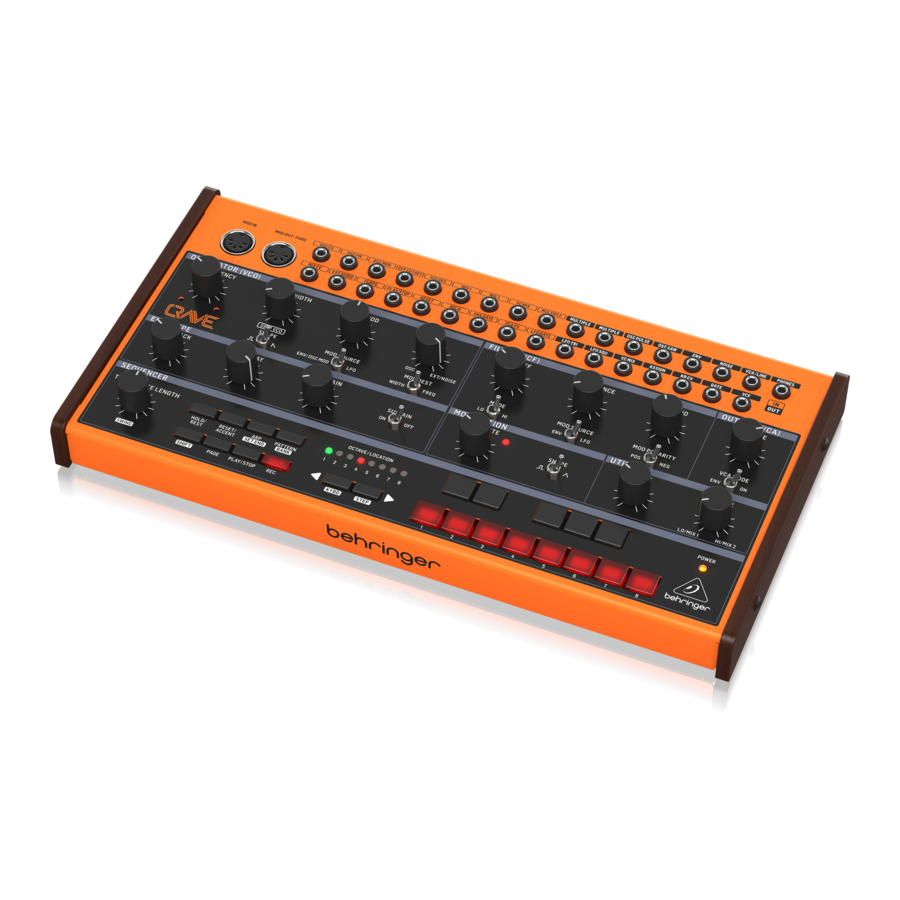
Controls


Oscillator (VCO) Section
- FREQUENCY - adjust the frequency of the oscillator, approximately one octave either side of center.
- PULSE WIDTH - adjust the pulse width of the oscillator (when in pulse mode) from narrow, to square (center position), to wide.
- SHAPE - select the waveform of the oscillator from pulse or reverse sawtooth.
- OSC MOD - select the depth of modulation applied to the oscillator. (5) MOD SOURCE - select the modulation source from the envelope (or an external modulation source), or the LFO.
- MIX - adjust the mix between the VCO output and the internal noise generator. If an external audio input is used, then this is added to the mix, instead of the noise.
- MOD DEST - select the modulation destination from pulse width modulation, or frequency modulation.
Filter (VCF) Section
- CUTOFF - adjust the cutoff frequency of the filter.
- MODE - select the VCF filter from low-pass or high-pass.
- RESONANCE - adjust the amount of enhancement given to the signals at the cutoff frequency.
- MOD SOURCE - select the modulation source of the VCF from the envelope generator or the LFO
- VCF MOD - adjust the depth of VCF modulation.
- MOD POLARITY- select the polarity of the VCF modulation.
Output (VCA) Section
- VOLUME - adjust the overall synthesizer output level.
- VCA MODE - select envelope, and the VCA is modulated by the envelope. In the ON position, the VCA output is the last key played, and is independent of envelope.
Envelope Section
- ATTACK - control the amount of time taken to reach the maximum level after a key is pressed.
- DECAY - control the amount of time taken to decay from the current level to minimum.
- SUSTAIN - control the level of the envelope that is sustained after the attack time has been reached.
- SUSTAIN ON/OFF - in the OFF position, the level will start to decay after the attack time is over. In the ON position, the sustain level will be held for as long as the key is held.
Modulation Section
- LFO RATE - adjust the frequency of the low frequency oscillator. The LED will flash at the LFO rate.
- SHAPE - select the LFO waveform from squarewave or triangular wave.
Utility Section
- GLIDE - adjust the amount of Glide time (Portamento), between notes on the keyboard. (If SHIFT is held, then the knob also adjusts the "ratchet" during sequencer operation.)
- VC MIX - adjust the VC MIX from LO/Mix 1 to HI/Mix 2. This control requires patch cords to operate, as it is outside of the internal sythesizer signal path.
Sequencer Section
- TEMPO/GATE LENGTH - this knob controls the sequencer tempo. During step editing, it also controls the GATE length. If SHIFT is held, then the knob also adjusts the SWING.
- HOLD/REST - during pattern playback, this allows you to hold the current step. During step editing, it allows you to enter a rest. During ARP mode, it allows you to enter/ exit ARP-Hold mode. During keyboard use, it allows you to hold the keys. (A footswitch connected to the HOLD input will also do this.)
- RESET/ACCENT - during playback, this allows you to reset the pattern back to step 1. During step editing, you can add an accent to a step.
- ARP (SET END) - In ARP mode, an arpeggio will play, based on the held notes using the CRAVE's 13 keyboard switches. Double-press to play and hold an Arpeggio. In Sequencer mode, pressing SHIFT and SET END together, followed by a STEP switch, will allow that step to become the end of the current pattern.
- PATTERN (BANK) - This button is used to access either the current pattern, or bank number, as follows:
PATTERN: Press PATTERN, and one of the 8 LOCATION LEDs will show the current pattern number (from 1 to 8). To change to a different pattern number, keep the PATTERN button held down and press any of the STEP buttons (1 to 8), or press <KYBD to decrease, or STEP> to increase the pattern number.
BANK: Press SHIFT and PATTERN, and one of the 8 LOCATION LEDs will show the current bank number (from 1 to 8). To change to a different bank number, keep both SHIFT and BANK held down, and press any of the STEP buttons (1 to 8), or press <KYBD to decrease, or STEP> to hincrease the bank number. - OCTAVE/LOCATION - these multi-colored LEDS show various details, such as the Octave, PATTERN number, BANK number, current PAGE, and GATE LENGTH.
- KEYBOARD/STEP SWITCHES - these multifunction switches allow you to view and select individual pattern steps, select a pattern number, select a pattern bank. They are used during recording of a pattern to show the current step. Active steps are illuminated with a steady red LED, and the current step flashes red. The switches are laid out as a 13-note keyboard. The octave can be moved up and down by pressing the <KYBD or STEP> switches, and the row of 8 LEDs will show the current octave. The switches are used to control the sequencer editing, as well as the arpeggiator operation.
- SHIFT - this is used to access the secondary features of some of the other sequencer controls, such as SET END, BANK, SWING, KYDB, and STEP. Hold down SHIFT and the other switch at the same time. For example SHIFT + PATTERN (BANK) will show the current BANK number in the LOCATOR LEDs.
- PAGE - each pattern can be up to 32 steps in length. This switch allows you to show each of the 4 pages of 8 steps each. The LOCATION LEDs 1 to 4, show which page you are on. If a pattern is playing, the STEP LEDs will show the steps in use on the current page.
- PLAY/STOP - starts or stops the playback of the pattern. If SHIFT is held at the same time, then this is the start of the pattern saving procedure.
- REC - press this to begin the recording of a new pattern. This is also used with SHIFT during the pattern saving procedure.
- KYBD - press SHIFT + KYBD to change the sequencer to keyboard mode.
- STEP - press SHIFT + STEP to change the sequencer to STEP mode.
- POWER - indicates that power is supplied to the unit and the rear-panel power switch is on.
MIDI Section
- MIDI IN - this 5-pin DIN jack receives MIDI data from an external source. This will commonly be a MIDI keyboard, an external hardware sequencer, a computer equipped with a MIDI interface, etc.
- MIDI THRU - this 5-pin DIN jack is used to pass through MIDI data received at the MIDI INPUT.
Patchbay (3.5 mm TS connections) Input Section
- OSC CV - oscillator pitch CV, at 1V/octave.
- OSC FM - oscillator frequency modulation.
- OSC MOD - oscillator modulation.
- VCF CUTOFF - VCF cutoff frequency CV.
- VCF RES - VCF Resonance CV.
- MIX 1 - mix 1 CV in, connected internally to VC MIX.
- MIX 2 - mix 2 CV in, connected internally to VC MIX.
- VC MIX - VC mix control CV in, connected internally to VC MIX.
- MULTIPLE - any signal entered here is passed out to both MULTIPLE outputs.
- MIX CV - mix CV.
- EXT AUDIO - external audio input.
- TEMPO - sequencer tempo.
- PLAY/STOP - sequencer play/stop.
- RESET - sequencer reset.
- HOLD - sequencer hold.
- ENV GATE - envelope gate.
- VCA CV - VCA CV.
- LFO RATE - LFO frequency rate CV.
Patchbay (3.5 mm TS connections) Output Section
- MULTIPLE - copy of multiple input.
- MULTIPLE - another copy of multiple input.
- OSC PULSE - oscillator pulse waveform output.
- OSC SAW - oscillator reverse sawtooth waveform output.
- ENV - envelope output.
- NOISE - noise output.
- VCA/LINE - connect this 3.5 mm TS output to the line-level audio input of your system. Make sure the volume is turned down and the system is turned off before making connections.
- PHONES - connect your headphones to this 3.5 mm TRS output. Make sure the volume is turned down before putting on headphones.
- LFO TRI - LFO triangular waveform output.
- LFO SQU - LFO square waveform output.
- VC MIX - VC mix output connected internally to VC MIX.
- ASSIGN - assign output.
- KB CV - keyboard CV output.
- GATE - gate output.
- VCF - VCF output.
Rear Panel
- MIDI CHANNEL - these 4 switches allow you to set the MIDI Channel number from 1 to 16, as shown in the chart.
- USB PORT - this USB type B jack allows connection to a computer. The CRAVE will show up as a classcompliant USB MIDI device, capable of supporting MIDI in and out. USB MIDI IN - accepts incoming MIDI data from an application. USB MIDI OUT - sends MIDI data to an application.
- POWER - turn the synthesizer on or off. Make sure all the connections are made before turning on the unit.
- DC INPUT - connect the supplied 12 V DC power adapter here. The power adapter can be plugged into an AC outlet capable of supplying from 100 V to 240 V at 50 Hz/60 Hz. Use only the power adapter supplied.
Getting started
OVERVIEW
This 'getting started' guide will help you set up the CRAVE analog synthesizer and briefly introduce its capabilities.
CONNECTION
To connect the CRAVE to your system, please consult the connection guide earlier in this document.
SOFTWARE SETUP
The CRAVE is a USB Class Compliant MIDI device, and so no driver installation is required. The CRAVE does not require any additional drivers to work with Windows and MacOS.
HARDWARE SETUP
Make all the connections in your system. Use the rear panel MIDI switches to set the CRAVE to a unique MIDI channel in your system. Connect an external MIDI keyboard directly to the CRAVE MIDI IN 5-pin DIN type input.
Apply power to the CRAVE using the supplied power adapter only. Ensure your sound system is turned down. Turn on the CRAVE rear panel power switch.
WARM UP TIME
We recommend leaving 15 minutes or more time for the CRAVE to warm up before recording or live performance. (Longer if it has been brought in from the cold.) This will allow the precision analog circuits time to reach their normal operating temperature and tuned performance.
OSCILLATOR VCO SECTION
The CRAVE has one main voltage controlled oscillator (VCO). The VCO waveform can be selected from pulse or reversesawtooth. When pulse is selected, the pulse width can be varied from narrow, squarewave (center) to wide pulse. Listen to the changes in sound that the waveforms and the change in pulsewidth make. The frequency can be adjusted up or down one octave, and allow fine tuning to other instruments. The VCO may be modulated either in pulse width, or in frequency. The source of the modulation can either be the envelope as detailed below, or the low frequency oscillator (LFO). The VCO can also be modulated using the OSC MOD input in the patch bay.
The amount or depth of VCO modulation can be adjusted using the OSC MOD control.
Use the MIX control to adjust the mix between the internal VCO (fully left)and the internal noise generator (fully right). If an external input signal is present at the EXT AUDIO input, then this will take the place of the noise in the mix.
FILTER (VCF) SECTION
Play with the cutoff frequency, and resonance controls, and listen to their effects on the sound.
The classic 24 dB/octave high pass and low pass filters allow a great deal of control over the sounds created by CRAVE.
The high-pass filter reduces the level of signals that are below the cutoff frequency. It effectively reduces the level of the fundamental, and lower order harmonics. The low-pass filter reduces the level of signals that are above the cutoff frequency. It reduces the levels of the higher-order harmonics.
The resonance control gives an enhancement to the signals at the crossover frequency.
The amount of VCF modulation can be varied with the VCF MOD control, and also the polarity can be reversed. For example, if modulation increases the cutoff frequency, then negative polarity will decrease it.
The VCF modulation source can either be the envelope or the LFO. All these features, in addition to using the patch bay, allows for a great deal of flexibility in sound creation.
MODULATION SECTION
The low frequency oscillator can be used to modulate the VCO and the VCF. The LFO frequency can be varied, and the waveform selected from square or triangular. An LED indicates the LFO rate.
ENVELOPE GENERATOR SECTION
The envelope generator can be used to modulate the cutoff frequency in the VCF section, and the voltage controlled amplifier (VCA). Envelope also can be used to modulate the VCO frequency and pulse width.
The controls for attack time, sustain level and decay time, allow you to adjust the envelope shape through a wide range.
PATCH BAY SECTION
This section allows you the versatility to create many different sounds, with an endless variety of options and configurations.
The VC MIX control is like having a separate mini-mixer or variable voltage source. It operates independently from the main signal path. It allows you to adjust a mix between the patchbay MIX 1 input and MIX 2 input, with possible modulation control from the VC MIX CV input. The patchbay VC MIX output can then be used to connect to other inputs in the patch bay.
If there are no MIX 1 or MIX 2 inputs connected, then theVC MIX output will vary from 0V (fully left) to +5 V (fully right). Experiment with this by connecting the VC MIX output to an input, and varying the VC MIX control.

Do not overload the 3.5 mm inputs. They can only accept the correct level of voltages as shown in the specification tables. The 3.5 mm outputs should only be connected to inputs capable of receiving the output voltages. Failure to follow these instructions may damage the CRAVE or external units.
SEQUENCER SECTION
The sequencer is described in further detail in this document.
It also features an arpeggiator, and a 13-key keyboard.
OUTPUT (VCA) SECTION
Use the main volume control to adjust the sound level in your headphones or speaker system.
Keep the level down low when first putting on headphones.
Keep the CRAVE power turned off when making any connections. Turn on the CRAVE before turning on any power amplifiers, and turn it off last. This will help prevent any turn on or turn off "pops or thumps" in your speakers.
The output can be modulated using the envelope, or it can be on continuously, playing and holding the last note played, until the next note occurs.
FIRMWARE UPDATE
Please check our website behringer.com regularly for any updates to the firmware of your CRAVE synthesizer. The firmware file can be downloaded and stored on your computer, and then used to update the CRAVE. It comes with detailed instructions on the update procedure.
Sequencer operation

OVERVIEW
The following details show some of the basic operation of the sequencer. You can create a short pattern of 2 or 3 steps, before trying more complex patterns. Adjust a single parameter at a time, such as gate length, ratchet, accent, glide, rest, tie, or swing, and then listen to its effect during playback.
It will help to choose a simple setting for the synthesizer, and no modulation of the VCO or VCF.
RECORDING A SIMPLE PATTERN
- Press SHIFT and <KYBD to select the keyboard mode.
- Initialise the current pattern by pressing SHIFT, RESET, and PATTERN at the same time. This will delete any previous steps of the current pattern.
- Press REC, and the STEP 1 switch LED will begin flashing, indicating this is the current step about to be added and edited. (If you cannot select REC, then repeat step 1.)
- Press any note on the CRAVE keyboard, or a rest as shown below. The <KYBD and STEP> switches can be used to change the octave. , indicated by 8 OCTAVE / LOCATION LEDs lit red.
- To enter a rest instead of a note, press the HOLD/REST switch. When a rest is added, the LOCATOR LED 8 will light.
- Press further notes. The next STEP switch LED will be flashing after each note or rest has been added.
- The gate length of a step can be adjusted using the TEMPO/GATE LENGTH control. The LOCATOR LEDs will turn red, showing the gate length from 1 to 8. If set to 8, this creates a tie with the next step. If the next step is the same note, this creates a longer note, as the 2 steps are tied.
- To create a "Ratchet," hold SHIFT, and turn the GLIDE control. The locator LEDs will show the number of ratchets from 1 to 4, in yellow. For example, with a setting of 4, the single step is split into 4 equal parts. When a ratchet is applied, the LOCATION LED 6 will light.
- To turn the GLIDE on for a step, turn up the GLIDE control. To turn off, turn it all the way down. When GLIDE is on for a step, the LOCATION LED 5 will light.
- To increase the brightness or accent, press the RESET/ ACCENT switch. When an accent is applied, the LOCATION LED 7 will light.
- Press REC when you have finished creating the pattern. It is not saved yet, but it can be played back. Caution: Do not turn off the unit, or create a new pattern, or the current unsaved pattern will be lost.
PLAYING A PATTERN
- Press PLAY/STOP to listen to the current pattern.
- If you decide not to save it, you can repeat the recording steps above to record a new pattern. Alternatively, press PATTERN and RESET to recall the currently saved pattern, and discard any changes.
- If you decide to save the pattern, you must follow the "SAVING A PATTERN" procedure shown below, or it will not remain in memory if a new pattern is begun, or the power is turned off.
- To create a SWING for this pattern, hold SHIFT and adjust the TEMPO/GATE LENGTH control. In the center position, no swing is applied, if turned down, only the off-beats will play, and if all the way up, only the on-beats will play. The SWING setting for the pattern is saved when the pattern is saved as shown below.
- While playing a pattern, you can: Press HOLD/REST to hold the current step. Press RESET/ACCENT to return to step 1. Press SHIFT and any STEP, and you can edit the gate length, rest, accent, ratchet, glide but not note. Press SHIFT and the same STEP again to exit step edit. (If playback is paused, the same operation can edit the note as well. Press PAGE to view the pattern page from 1 to 4. Press SHIFT and PAGE to return to automatic page turning. Press SHIFT and ARP/SETEND and a STEP to change the sequence end step. PLAY/STOP to pause playback.
- Press PLAY/STOP.
- Note: To play in reverse, press SHIFT and PLAY/STOP.
SAVING A PATTERN
- Press and hold SHIFT + PLAY/STOP for 2 seconds until the LOCATOR LED of the current pattern number begins to flash green slowly.
- Press a STEP switch 1 to 8 to select the new desired pattern number.
- Press PATTERN + STEP switch 1 to 8 to select the desired bank number.
- Press SHIFT + REC to save the pattern and exit the save mode.
RECALLING A SAVED PATTERN
- Press and hold PATTERN. The LOCATION LED will show the current pattern number. Use the <KYBD or STEP> switches to move up and down through the patterns 1 to 8, or press a STEP switch 1 to 8. You can also do this while a pattern is playing.
- Press and hold SHIFT and PATTERN. The LOCATION LED will show the current bank number. Use the <KYBD or STEP> switches to move up and down through the banks 1 to 8, or press a STEP switch 1 to 8. You can also do this while a pattern is playing.
- Press PLAY/STOP to play back the current pattern.
- During playback, the LOCATION LEDs will show the current page of the pattern (1 to 4), and the STEP Switch LEDs will show the steps moving.
LIVE PERFORMANCE
During playback, temporary adjustments can be made as follows.
(None of these are saved with the pattern.)
- To add Ratchet to all steps of the pattern, press SHIFT and adjust the GLIDE control.
- To add SWING, press SHIFT and adjust the TEMPO control.
- To mute the pattern, press SHIFT + HOLD/REST.
- To add an accent to all steps, press SHIFT + RESET/ACCENT.
- Use the <KYBD and STP> switches to change the octave. The LEDs will show the current Octave in red.
EDITING A PATTERN
- To edit a pattern in Keyboard mode, press REC. The STEP switch LEDs will light.
- Press PAGE to select the pattern page from 1 to 4 to be edited. The green LOCATION LEDs 1 to 4 will show the current page and the PAGE button LED lit to indicate the page is locked (press SHIFT and PAGE to unlock).
- Press SHIFT and the STEP switch you want to edit. You can enter a new note, or a rest, and adjust any of the other parameters such as ratchet, glide on/off, and so on.
- Press SHIFT and the next STEP switch to be edited. (The steps will not automatically advance to the next step in line; you can choose which steps to edit next.)
- Press REC to exit the editing mode.
- Press PLAY/STOP to listen to the edited pattern.
- Remember to save the pattern using the "SAVING A PATTERN" procedure above.
CREATING A PATTERN IN STEP MODE
- Press SHIFT and STEP> to select the Sequencer's STEP mode. The flashing LOCATION LED will turn from green (Keyboard mode) to yellow (Step mode).
- Initialise the current pattern by pressing SHIFT, RESET, and PATTERN at the same time. This will delete any previous steps of the current pattern. (If you want to use the current pattern instead, then do not initialise it.)
- Press PAGE to move to a desired page of your pattern. Then press SET END and a STEP switch to choose the length of the pattern. For example, if you are on page №1 and press SET END + 8, then the pattern length is 8 steps. If you press PAGE and reach page №4, and press SET END + 8, then the pattern will be 32 steps long (4 pages of 8 steps each).
- When the desired SET END is selected, all the STEP switch LEDs up to that step will be on solid red.
- Press SHIFT and any one of the STEP switches at the same time. It will begin to flash, indicating it is the current step about to be edited. You can now add a note, or a rest, or any of the other functions described above in the Keyboard mode, such as Ratchet, Glide, Accent, change gate length and so on.
- Press SHIFT and the current STEP switch to finish editing that step. It will stop flashing.
- Repeat procedure steps 5 and 6 above, until all your required steps are good.
- Press PLAY/STOP to play the pattern.
- While playing, you can add temporary adjustments as shown in the "LIVE PERFORMANCE" procedure above.
SAVING A PATTERN IN STEP MODE
Save the pattern using the "SAVING A PATTERN" procedure shown above for the KEYBOARD mode.
Do not turn off the unit, or create a new pattern, or the current unsaved pattern will be lost.
Tempo and Assign Mode Select
The tempo input and assign mode may be changed using the following procedure:
- Press SHIFT+ HOLD/REST + 8 to enter the setting mode. The LOCATION LED 1 will blink yellow.
- Press <KYBD or STEP> to select pages 1 or 2. The yellow LOCATION LED shows the current page:
- Page 1 allows you to select the tempo input mode, 1 to 3. (Please see Programming Tempo Input Modes, below)
- Page 2 allows you to select the assign output mode, 1 to 16. (Please see Assignable Output Mode, below)
- Press STEP switches 1 to 8 to select numeric values from 1 to 8. The current value is indicated by a green LOCATION LED.
- To access values 9 to 16, press SHIFT + STEP switch 1 to 8. The current value is shown by a red LOCATION LED.
- Note: If a setting is on the same LED number as the current page LED, then the LED will flash alternately between the yellow page color and the green or red parameter color.
- Press SHIFT + HOLD/REST + 8 to exit the setting mode, and save any parameter changes.
Programming Tempo Input Modes:
- TEMPO CV INPUT MODE
- TEMPO SINGLE CLOCK ADVANCE MODE
- TEMPO DIN SYNC MODE
Assignable Output Modes:
- Accent
- Sequencer Clock
- Sequencer Clock/2
- Sequencer Clock/4
- Sequencer Step Ramp
- Sequencer Step Saw
- Sequencer Step Triangle
- Sequencer Step Random
- Sequencer Step 1 Trigger Output
- MIDI Velocity
- MIDI Channel Pressure
- MIDI Pitch Bend
- MIDI CC1
- MIDI CC2
- MIDI CC4
- MIDI CC7
Poly Chain Function

System Mode
| POWER LED | Mode |
| Amber | Normal Mode |
| Red | Poly Chain Mode |
Please use the "SynthTool.exe" to confi gure the Poly Chain mode. The POWER LED will turn red during Poly Chain mode.
To enter/exit Poly Chain mode, quickly toggle the SUSTAIN switch more than 4 times while the SEQUENCER LED are fl ashing after power up.
MIDI information
MIDI message
| Status | Second | Third | Parameter | Description | |
| Channel Message | 8n | kk | vv | [0, 7F] | Note Off |
| 9n | kk | vv | [0, 7F] | Note On | |
| Bn | 01 | vv | [0, 7F] | CC1 | |
| Bn | 02 | vv | [0, 7F] | CC2 | |
| Bn | 04 | vv | [0, 7F] | CC4 | |
| Bn | 05 | vv | [0, 7F] | Glide | |
| Bn | 07 | vv | [0, 7F] | CC7 | |
| Bn | 0C | vv | [0, 7F] | Tempo | |
| Bn | 32 | vv | [0, 7F] | Attack | |
| Bn | 33 | vv | [0, 7F] | Decay | |
| Bn | 34 | vv | [0, 7F] | Sustain | |
| Bn | 41 | vv | [0, 7F] | Glide On/Off | |
| Bn | 7B | — | — | All Notes Off | |
| Dn | kk | — | [0, 7F] | After Touch | |
| En | bb | bb | [0, 3FFF] | Pitch Bend | |
| SysRT | F8 | — | — | — | Timing Clock |
| FA | — | — | — | Start | |
| FB | — | — | — | Continue | |
| FC | — | — | — | Stop |
Examples
| Function | Command (1) |
| Note on | 90 3C 64 |
| Note off | 80 3C 40 |
| Select glide time MIN | B0 05 00 |
| Select glide time MAX | B0 05 7F |
| Glide on | B0 41 00 |
| Glide off | B0 41 7F |
| All notes off | B0 7B |
Note: 1, MIDI input channel 1.
Specifications
| Synthesizer Architecture | |
| Number of voices | Monophonic |
| Type | Analog |
| Oscillators | 1 (8.176 to 8.372k Hz) |
| LFO | 1 (0.1 to 350 Hz) |
| VCF | 1 low pass, high pass (24 dB/octave slope) |
| Envelopes | ADS, selectable for VCO, VCF, VCA |
| Connectivity | |
| Power input | DC input connector |
| Power switch | Push button on/off |
| MIDI In/Thru | MIDI In and MIDI Thru, 5-pin DIN |
| MIDI channel switch | Channel selection/ 16 channels |
| USB (MIDI) | USB 2.0, type B |
| Outputs | VCA/line output: 3.5mm TS, unbalanced, max. +8 dBu |
| Outputs impedance | 1 kΩ |
| Headphones | 3.5 mm TRS, max.10 mW@32 Ω |
| Headphones output impedance | 16 Ω |
| USB | |
| Type | Class compliant USB 2.0, type B |
| Supported Operating Systems | Windows 7 or higher Mac OS X 10.6.8 or higher |
| Oscillator (VCO) Section | |
| Type | 3340 |
| Controls | Frequency: -5 to +5 Pulse width: 5 to 95% Oscillator modulation: 0 to 10 Mix: -5 to +5 |
| Switches | Shape: pulse, reverse saw Modulation source: env/osc mod, LFO Modulation destination: width, frequency |
| Filter (VCF) Section | |
| Controls | Cutoff frequency: 0 to 10 (20 Hz to 20 kHz) Resonance: 0 to 10 VCF modulation: 0 to 10 |
| Switches | Filter mode: low pass, high pass Modulation source: env, LFO Modulation polarity: positive, negative |
| Output (VCA) Section | |
| Controls | Volume: 0 to 10 |
| Switches | VCA mode: envelope, on |
| Envelope Section | |
| Controls | Attack time: 0 to 10 (2 ms to 3 s) Decay time: 0 to 10 (2 ms to 5 s) Sustain level: 0 to 10 (0 to 8 V) |
| Switches | Sustain: on, off |
| Modulation Section | |
| Controls | LFO rate: 0 to 10 |
| Switches | Shape: pulse, triangular |
| LED | LFO rate |
| Utility Section | |
| Controls | Glide time: 0 to 10 (0 to 2 s) VC mix: lo/mix 1 to hi/mix 2 |
| Sequencer/Arpeggiator Section | |
| Number of step | 32 steps maximum per pattern |
| Number of patterns | 64 patterns maximum |
| Memory storage | 8 banks with 8 patterns each |
| Controls | Tempo/gate length |
| Switches | Hold/rest, reset/accent, arp/set end, pattern/bank, shift, page, play/stop, record, keyboard mode, step mode, 13 note keyboard |
| LEDs | 8x octave/location |
| Inputs and Outputs (TS 3.5 mm) | |
| Inputs | OSC cv: -5 to +5 V OSC fm: -5 to +5 V OSC mod: -5 to +5 V VCF cutoff: -5 to +5 V VCF resonance: -5 to +5 V Mix 1: -5 to +5 V Mix 2: -5 to +5 V VC mix: -5 to +5 V Multiple: -5 to +5 V Mix cv: -5 to +5 V Ext audio: -5 to +5 V Tempo: -5 to +5 V Play/stop: more than 3.2 V Reset: more than 3.2 V Hold: more than 3.2 V Env gate: more than 3.2 V VCA CV: -5 to +5 V LFO rate: -5 to +5 V |
| Outputs | Multiple: -5 to +5 V Multiple: -5 to +5 V OSC pulse: +/-5 V OSC saw: +/-5 V Env: 0 to 8 V Noise: +/-5 V LFO triangle: +/-5 V LFO square: +/-5 V VC mix: -5 to +5 V Assign: 0/+5 V or +/-5 V KB CV: -5 to +5 V Gate: 0/+5 V VCF: +/-5 V |
| Power Requirements | |
| External power adaptor (use only the supplied adapter) | 12 VDC, 1000 mA |
| Power consumption | 3 W maximum |
| Indicator | Power LED |
| Environmental | |
| Operating temperature range | 5°C – 40°C (41°F – 104°F) |
| Physical | |
| Dimensions (H x W x D) | 47 x 320 x 164 mm (1.85 x 12.6 x 6.46") |
| Weight | 1.5 kg (3.3 lbs) |
| Shipping weight | 1.97 kg (4.3 lbs) |
FEDERAL COMMUNICATIONS
COMMISSION COMPLIANCE
INFORMATION

Responsible Party Name: Music Tribe Commercial NV Inc.
Address: 5270 Procyon Street Las Vegas, NV 89118
USA Phone Number: +1 702 800 8290
CRAVE complies with the FCC rules as mentioned in the following paragraph: This equipment has been tested and found to comply with the limits for a Class B digital device, pursuant to part 15 of the FCC Rules. These limits are designed to provide reasonable protection against harmful interference in a residential installation. This equipment generates, uses and can radiate radio frequency energy and, if not installed and used in accordance with the instructions, may cause harmful interference to radio communications. However, there is no guarantee that interference will not occur in a particular installation. If this equipment does cause harmful interference to radio or television reception, which can be determined by turning the equipment off and on, the user is encouraged to try to correct the interference by one or more of the following measures:
- Reorient or relocate the receiving antenna.
- Increase the separation between the equipment and receiver.
- Connect the equipment into an outlet on a circuit different from that to which the receiver is connected.
- Consult the dealer or an experienced radio/TV technician for help.
This device complies with Part 15 of the FCC rules. Operation is subject to the following two conditions:
- this device may not cause harmful interference, and
- this device must accept any interference received, including interference that may cause undesired operation.

Changes or modifications to the equipment not expressly approved by Music Tribe can void the user's authority to use the equipment.

Documents / ResourcesDownload manual
Here you can download full pdf version of manual, it may contain additional safety instructions, warranty information, FCC rules, etc.
Download Behringer CRAVE - Analog Semi-Modular Synthesizer Quick Start Guide
Advertisement


Need help?
Do you have a question about the CRAVE and is the answer not in the manual?
Questions and answers