Table of Contents
Advertisement
Quick Links
Advertisement
Table of Contents

Related Manuals for Keysight AP5041A G3


Summary of Contents for Keysight AP5041A G3
- Page 1 Keysight AP5041A G3 and AP5042A G3 Vector Signal Generator USER’S MANUAL...
-
Page 2: Safety Notices
The hardware and/or software into a foreign language) without the EULA. Keysight shall be under described in this document are prior agreement and written no obligation to update, revise or... -
Page 3: Where To Find The Latest Information
URLs, according to the name of your product: https://www.keysight.com/us/en/support/AP5041A/ap5041a-g3-vector-signal-generator-up-to-40-ghz.h https://www.keysight.com/us/en/support/AP5042A/ap5042a-g3-vector-signal-generator-up-to-40-ghz.h To receive the latest updates by email, subscribe to Keysight Email Updates at the following URL: https://support.keysight.com Information on preventing instrument damage can be found at: http://www.keysight.com/find/PreventingInstrumentDamage Is your product software up-to-date? Periodically, Keysight releases software updates to fix known defects and incorporate product enhancements. - Page 4 If you discover a cybersecurity issue that you suspect may involve Keysight's proprietary software, or third-party software supplied by Keysight as part of a product, or that may affect the operation of Keysight products, we encourage you to report it to us using this form: https://www.keysight.com/us/en/about/quality-and-security/security/product-and-solution-cyber-security/report-...
-
Page 5: Table Of Contents
Contents Contents 1 Quick Start Introduction Models Covered in this Manual Available Casing Data Connections Signal Connections Transportation Safety Information Safety Symbols Instrument Markings General Safety Considerations Technical Specifications Minimum Distances Energizing and de-Energizing Protective Earth Proper Operating Conditions Environmental Information Getting Started Included Material System Requirements... - Page 6 Contents CONTROL Menu CW Menu SWEEP Menu MODULATION Menu REFERENCE Menu TRIGGER Menu LF OUT Menu Simultaneously Controlling Multiple Signal Generators from one PC Store and Load Instrument States Setting Network Configuration Multi-Session Option Device Port Setting Connecting two devices using a non-default port and non-default network interface Firmware Upgrade Combined Modulation...
- Page 7 Contents Repair Warranty Information...
- Page 8 Contents...
-
Page 9: Quick Start
The following topics can be found in this section: “Introduction” on page 10 “Models Covered in this Manual” on page 10 “AP5041A G3 Desktop Front and Rear Panel Connectors” on page 11 — — “AP5042A G3 2U Front and Rear Panel Connectors” on page 12 “Minimum Distances”... -
Page 10: Introduction
Addressing these demanding requirements, Keysight’s AP5041A and AP5042A vector signal generators (VSGs) provide frequency coverage to 40 GHz and are available as single output desktop units or rack-mount instruments with multiple phase-coherent outputs. -
Page 11: Ap5041A G3 Desktop Front And Rear Panel Connectors
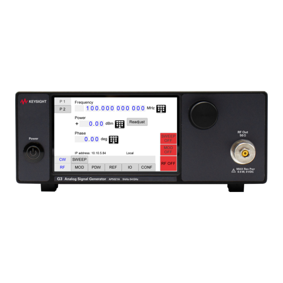
Quick Start Models Covered in this Manual AP5041A G3 Desktop Front and Rear Panel Connectors Figure 1-1 AP5041A front panel (with touch display) 1. Touch Display - shows information on the current function, such as frequency, power, and reference. 2. Rotary Button - used to change the value selected on the display. -
Page 12: Ap5042A G3 2U Front And Rear Panel Connectors
4. RF LED (1 through 4) - indicates whether the RF signal is on or off. 5. RF OUT (1 through 4) - provides the output for generated signals. The impedance is 50 . Please refer to the data sheet for more details. Keysight AP5041A/AP5042A User’s Manual... - Page 13 11. Fuse Holder - Provides an exchangeable fuse. 12. AC Power - Connector for AC power 13. ON/Off Switch - Turns the instrument on or off. 14. Ground Screw - Used to connect the device to a ground reference. Keysight AP5041A/AP5042A User’s Manual...
-
Page 14: Minimum Distances
Safety of any system incorporating the equipment is the responsibility of the assembler of the system. For an adequate cooling, the minimum distances between the device and another object, such as walls, rack cabinet walls or other equipment must be respected. Keysight AP5041A/AP5042A User’s Manual... - Page 15 Quick Start Minimum Distances — A: 1 mm — B: 1 mm — C: 50 mm — D: 50 mm Figure 1-5 Minimum distance for the 2U Keysight AP5041A/AP5042A User’s Manual...
- Page 16 Quick Start Minimum Distances Desktop — A: 0 mm — B: 0 mm — C: 50 mm — D: 50 mm — E: 150 mm — F: 150 mm Figure 1-6 Minimum distance for the Desktop Keysight AP5041A/AP5042A User’s Manual...
-
Page 17: Energizing And De-Energizing
Energizing and de-Energizing Energizing and de-Energizing To energize the device, apply the following voltage to the following connector. Use Keysight supplied power cord or one with same or better electrical rating. The Mains wiring, and connectors shall be compatible with the connector used in the premise electrical system. -
Page 18: Data Connections
In general, all connections between the signal generator and another device should be made as short as possible and must be well shielded. It is recommended to use a high-quality cable with low loss especially for frequencies above 20 GHz. Keysight AP5041A/AP5042A User’s Manual... -
Page 19: Transportation
Quick Start Transportation Transportation The devices must only be transported with the packaging supplied by the manufacturer. The device can be lifted or transported in any orientation. Keysight AP5041A/AP5042A User’s Manual... -
Page 20: Safety Information
Marking Description This symbol marks the standby position of the power line switch. This symbol marks the ON position of the power line switch. This symbol marks the OFF position of the power line switch. Keysight AP5041A/AP5042A User’s Manual... - Page 21 The UK conformity mark is a UK government owned mark. Products showing this mark comply with all applicable UK regulations. The Keysight email address is required by EU directives applicable to our product. The CSA mark is a registered trademark of the CSA International.
- Page 22 EU DIRECTIVE and other National legislation. Please refer to www.keysight.com/go/takeback to understand your trade-in options with Keysight, in addition to product takeback instructions. China Restricted Substance Product Label. The EPUP (environmental protection use period) number in the center indicates the time period during which no hazardous or toxic substances or elements are expected to leak or deteriorate during normal use and generally reflects the expected useful life of the product.
-
Page 23: General Safety Considerations
(heavy-metal dust such as nickel) may be released. For this reason, the product may only be disassembled or opened by specially trained personnel. Improper disassembly may be hazardous to your health. National waste disposal regulations must be observed. Keysight AP5041A/AP5042A User’s Manual... -
Page 24: Getting Started
The instrument’s power adapter is auto-ranging. Be sure the supply voltage is within +/-10% of the specified rating. System Requirements The Keysight graphical user interface requires at least the minimum system requirements to run one of the supported operating systems. Operating system... -
Page 25: Unpacking The Instrument
Applying Power Place the instrument on the intended workbench and plug into power. Using supplies other than those provided by Keysight may lead to malfunction and damage of the Instrument. For the AP5041A only, press the power button and the instrument will initialize and momentarily display the model number, firmware revision and product serial number. - Page 26 USBTMC device. If you want to work with the Keysight GUI, it must be installed with USB support selected. Then the GUI will detect all attached devices automatically. Open the GUI and follow the instructions “Using the Graphical User Interface (GUI)”...
-
Page 27: Shutting Down The Signal Generator
OK otherwise browse for the path to GUI installation directory. Finally close all open dialogs by selecting OK. Now your Windows Firewall will not block requests from the GUI. Shutting Down the Signal Generator Press the on/off switch on the rear panel to turn off. Keysight AP5041A/AP5042A User’s Manual... - Page 28 Quick Start Getting Started Keysight AP5041A/AP5042A User’s Manual...
- Page 29 Keysight AP5041A/AP5042A Vector Signal Generators User’s Guide Front Panel Operation (Applies to the AP5041A only) The following topics can be found in this chapter: “RF 50 Ω Connector” on page 31 “Rotary Button” on page 31 “Front Panel Settings” on page 31 “RF >...
- Page 30 Front Panel Operation (Applies to the AP5041A only) The front panel display allows you to access many of the AP5041A functions. However, the GUI interface allows you access all available functions. Figure 2-1 Front panel with touch display Keysight AP5041A/AP5042A User’s Manual...
-
Page 31: Rf 50 Ω Connector
You can set the CW frequency, power level and phase from the CW menu. P1 and P2 work as a toggle switch. Therefore, if you are currently viewing P2 and want to go to P1 then press P2 again. Keysight AP5041A/AP5042A User’s Manual... -
Page 32: Rf > Sweep Menu
The Sweep menu on the instrument front panel has three submenus. The Configuration submenu provides additional settings for the Frequency and Power submenus. — Frequency — Power — Configuration The Configuration submenu provides additional settings for the Frequency and Power submenus. — Trigger Keysight AP5041A/AP5042A User’s Manual... - Page 33 INFinite, and 1 (single repetition). The sweep is started by pressing the RF On/Off button. The remote GUI allows you to set the same settings above plus, Sweep Mode, RF blank until trigger, and ALC Mode. Keysight AP5041A/AP5042A User’s Manual...
- Page 34 Front Panel Operation (Applies to the AP5041A only) Front Panel Settings Figure 2-5 Power Display RF > Sweep > Configuration Submenu Figure 2-6 Panel 1 Configuration Display Keysight AP5041A/AP5042A User’s Manual...
-
Page 35: Rf > Sweep > Trigger Submenu
RF > Sweep > Trigger Submenu — Out — Source — Configure RF > Sweep Trigger > Out Submenu The Trigger Out submenu accesses the trigger output delay, pulse width, polarity, and output mode. Figure 2-8 Out Display Keysight AP5041A/AP5042A User’s Manual... -
Page 36: Modulation Submenus
The Configure submenu is used set the trigger mode, type and delay. Figure 2-10 Configure Display Modulation Submenus The modulation section gives access to most settings related to available modulations. The different types of modulations are grouped in submenus, which include but may not be limited to: Keysight AP5041A/AP5042A User’s Manual... - Page 37 Including settings for VOR, ILS, and DME — Digital modulations (AP5041A Option 431) Modulation > ARB Submenu Sets the parameters for an arbitrary modulation. — WAVE — SD — FCP Modulation > ARB > WAVE Submenu Figure 2-11 WAVE Display Keysight AP5041A/AP5042A User’s Manual...
- Page 38 Front Panel Operation (Applies to the AP5041A only) Front Panel Settings Modulation > ARB > SD Submenu Figure 2-12 Secure Digital (SD) Card Display Modulation > ARB > AIQ Submenu Figure 2-13 AIQ (Analog In-phase and Quadrature) Display Keysight AP5041A/AP5042A User’s Manual...
- Page 39 Main and Out work as a toggle switch. Therefore, if you are currently viewing Out and want to go to Main then press Out again. In the pulse modulation submenu the pulse width, pulse period and pulse trigger can be configured in the following tabs: — Main Keysight AP5041A/AP5042A User’s Manual...
- Page 40 Front Panel Operation (Applies to the AP5041A only) Front Panel Settings Figure 2-15 Main Display — OUT Figure 2-16 OUT Display Modulation > ANLG > AM (Amplitude Modulation) Submenu In the amplitude modulation submenu the internal amplitude modulation can be accessed. Keysight AP5041A/AP5042A User’s Manual...
- Page 41 Modulation > ANLG > PM (Phase Modulation) Submenu In the phase modulation submenu the internal and external phase modulation can be accessed. It is possible to change between internal and external modulation source and change modulation parameters. Keysight AP5041A/AP5042A User’s Manual...
- Page 42 Front Panel Operation (Applies to the AP5041A only) Front Panel Settings Figure 2-19 Phase Display Modulation > AWGN Submenu Figure 2-20 AWGN Display Keysight AP5041A/AP5042A User’s Manual...
- Page 43 Front Panel Operation (Applies to the AP5041A only) Front Panel Settings Modulation > AVIO > VOR (Very High Frequency) Submenu Figure 2-21 AVIO VOR Main Display Figure 2-22 AVIO VOR CONF1 Display Keysight AP5041A/AP5042A User’s Manual...
- Page 44 Front Panel Operation (Applies to the AP5041A only) Front Panel Settings Figure 2-23 AVIO VOR CONF2 Display Figure 2-24 AVIO VOR IDENT Display Keysight AP5041A/AP5042A User’s Manual...
- Page 45 Front Panel Operation (Applies to the AP5041A only) Front Panel Settings Modulation > AVIO > ILS (Instrument Landing System) LOC (Localizer) Submenu Figure 2-25 AVIO > ILS LOC > MAIN Display Figure 2-26 AVIO > ILS LOC > CONF1 Display Keysight AP5041A/AP5042A User’s Manual...
- Page 46 Front Panel Operation (Applies to the AP5041A only) Front Panel Settings Figure 2-27 AVIO > ILS LOC > CONF2 Display Figure 2-28 AVIO > ILS LOC > IDENT Display Keysight AP5041A/AP5042A User’s Manual...
- Page 47 Front Panel Operation (Applies to the AP5041A only) Front Panel Settings Modulation > AVIO > ILS (Instrument Landing System) GS (Glideslope) Submenu Figure 2-29 AVIO > ILS GS > MAIN Display Figure 2-30 AVIO > ILS GS > CONF1 Display Keysight AP5041A/AP5042A User’s Manual...
- Page 48 Front Panel Operation (Applies to the AP5041A only) Front Panel Settings Figure 2-31 AVIO > ILS GS > CONF2 Display Modulation > AVIO > DME (Distance Measuring Equipment) Submenu Figure 2-32 AVIO > DME > MAIN Display Keysight AP5041A/AP5042A User’s Manual...
- Page 49 Front Panel Operation (Applies to the AP5041A only) Front Panel Settings Figure 2-33 AVIO > DME > SHAPE Display Figure 2-34 AVIO > DME > CONF2 Display Keysight AP5041A/AP5042A User’s Manual...
- Page 50 Front Panel Operation (Applies to the AP5041A only) Front Panel Settings Figure 2-35 AVIO > ILS GS > IDENT Display Modulation > AVIO > NDB (Non Direction Beacon) Submenu Figure 2-36 AVIO > NDB > MAIN Display Keysight AP5041A/AP5042A User’s Manual...
- Page 51 Front Panel Operation (Applies to the AP5041A only) Front Panel Settings Figure 2-37 AVIO > NDB > IDENT Display Modulation > QAM Figure 2-38 QAM Display Keysight AP5041A/AP5042A User’s Manual...
- Page 52 Front Panel Operation (Applies to the AP5041A only) Front Panel Settings Modulation > Trigger Figure 2-39 Configure Display Figure 2-40 Source Display Keysight AP5041A/AP5042A User’s Manual...
-
Page 53: Reference Submenu
Input Output (IO) Submenu This menu includes configurations for input and output ports of the device. Submenus included here, are: — Multifunction Output - Select the signal to be output at each of the multifunction ports. Keysight AP5041A/AP5042A User’s Manual... - Page 54 MF 1 and MF 2 work as a toggle switch. Therefore, if you are currently viewing MF 2 and want to go to MF 1 then press MF 2 again. Figure 2-43 MFO > MF1 Display Figure 2-44 MFO > MF 2 Display Keysight AP5041A/AP5042A User’s Manual...
- Page 55 AIN 2 and want to go to AIN 1 then press AIN 2 again. Figure 2-45 AIN > AIN1 Display Figure 2-46 AIN > AIN2 Display IO > FCP (Fiber Channel Protocol) Submenu This menu is available for both MF1 and MF2. Keysight AP5041A/AP5042A User’s Manual...
-
Page 56: Configuration
— DISPlay — INFO — TEST Configuration > Preset Submenu In the Preset Settings submenu, specific settings can be stored to the instrument or loaded from the instrument. You can also restore the factory default settings. Keysight AP5041A/AP5042A User’s Manual... - Page 57 In the Communication submenu, IP address, subnet mask and DHCP can be configured. Figure 2-49 Communication Display Configuration > Display Submenu In the Display submenu, configuration of the instrument via the display can be disabled or enabled. Keysight AP5041A/AP5042A User’s Manual...
- Page 58 In the Info Submenu, information about the device is shown (serial number, firmware version, and options installed). Figure 2-51 Info Display Configuration > Test Submenu The Test Submenu allows you to perform a self test on the instrument. Keysight AP5041A/AP5042A User’s Manual...
- Page 59 Front Panel Operation (Applies to the AP5041A only) Front Panel Settings Figure 2-52 Test Display Configuration > Tune Submenu Figure 2-53 Tune Display Allows you to adjust frequency tuning. Keysight AP5041A/AP5042A User’s Manual...
- Page 60 Front Panel Operation (Applies to the AP5041A only) Front Panel Settings Keysight AP5041A/AP5042A User’s Manual...
-
Page 61: Using The Graphical User Interface (Gui)
Keysight AP5041A/AP5042A Vector Signal Generator User’s Manual Using the Graphical User Interface (GUI) This section describes the following features: “Start the Signal Generator GUI” on page 62 “Simultaneously controlling Multiple Signal Generators from one PC” on page 63 “Setting Network Configuration” on page 63 “Device Port Setting”... -
Page 62: Start The Signal Generator Gui
Start the Signal Generator GUI Start the Signal Generator GUI Keysight’s graphical user interface provides an intuitive control of the signal generator. It runs under any Windows operating system. Make sure the software is installed correctly and the computer’s firewall is configured properly. -
Page 63: Simultaneously Controlling Multiple Signal Generators From One Pc
Connecting to Devices Using a Non-default Port There are two options for connecting to a device when its default listening port has been changed. — Specify a temporary port Keysight AP5041A/AP5042A User’s Manual... -
Page 64: Setting The Gpib Address
GPIB submenu in the Control tab. Valid GPIB addresses range from 1 to 30. To verify GPIB functionality, use the VISA Assistant available with the Keysight IO Library or the Getting Started Wizard available with the National Instrument IO Library. -
Page 65: Remotely Programing The Signal Generator
Reconnect to the instruments after booting is completed and continue with the updated firmware. Remotely Programing the Signal Generator The signal generator can be remotely programmed with the use of SCPI commands. Please refer to the Programmer's Manual for details. https://www.keysight.com/us/en/support/AP5041A/ap5041a-g3-vector-sig nal-generator-up-to-40-ghz.html# Keysight AP5041A/AP5042A User’s Manual... - Page 66 The following section descibes basic functions of the device are explained. Examples demonstrate a selection of modulated signals that can be generated with the APVSG. The GUI is used to control the signal generator in the examples. Keysight AP5041A/AP5042A User’s Manual...
-
Page 67: Menus
— Arbitrary - sets either Marker or Trigger signals at the output. Marker signals must be defined for the replayed segment selected in the Segment tab. The arbitrary trigger can be configured in the modulation section. Keysight AP5041A/AP5042A User’s Manual... - Page 68 The sweep trigger can be configured in the RF > Carrier > Sweep tab. Used to set up the fast control port (option FCP). Refer to application note: — Fast-Control-Port-with-MDR-26-Pin-Connector.pdf Keysight AP5041A/AP5042A User’s Manual...
-
Page 69: Carrier Section
— Total - provides the combined crest factor of the modulated carrier and AWGN, if enabled. — Refresh - updates the actual crest factor values after modulation has been changed. Refer to the G3-Vector-Signal-Generator-RF-Output-Modes application note. Keysight AP5041A/AP5042A User’s Manual... -
Page 70: Modulation Section
4. Select Reduce Crest Factor if required. 5. Tone frequencies and relative powers are displayed (scroll down if not all tones are visible on the screen). 6. Change relative power by manually entering the desired value in the Power (rel) field. Keysight AP5041A/AP5042A User’s Manual... - Page 71 Example: Pulsed chirp 1. Select CW and appropriate carrier parameters in the Carrier section. 2. In the Modulation > Generator tab, select Pulsed Chirp and specify the pulse parameters, as shown below. 3. Select the Generate button. Keysight AP5041A/AP5042A User’s Manual...
- Page 72 IQ phaser plot In the Generation Preview area, the number of samples and the estimated upload time is also provided. 4. Select Upload to Device to upload the generated modulation. 5. Select the IQ Modulation to turn on IQ Modulation. Keysight AP5041A/AP5042A User’s Manual...
- Page 73 Other modulation formats are FM Chirp, Barker and BPSK (binary phase shift keying). — Pulse Type - Two modulation types are available: Trapezoidal and Raised Cosine. — Pulses - In this list pulse sections can be defined. Keysight AP5041A/AP5042A User’s Manual...
- Page 74 — PM (phase modulation) — AM (amplitude modulation) — Pulse (pulse modulation) Example FM 1. Select the CW section and set the appropriate carrier parameters. 2. From the Modulation section, select the Analog Modulation tab > FM. Keysight AP5041A/AP5042A User’s Manual...
- Page 75 — Arbitrary Trigger, Playback Rate, Auto Playback Rate, Update Now, refer to “General Modulation Functions” on page Digital Modulation Custom Digital Modulation (Option 431 - Internal digital modulation schemes) tab you can choose between the following internally generated modulations: Keysight AP5041A/AP5042A User’s Manual...
- Page 76 3. In the Modulation area, select the Format dropdown and select QAM 64. 4. Specify the QAM 64 parameters: — Filter Type — Filter Param — Pattern Length — Oversampling — Symbol Rate 5. Select the Digital Modulation off button to turn on modulation of the carrier. Keysight AP5041A/AP5042A User’s Manual...
- Page 77 I and Q modulation signals from the I IN and Q IN (for each channel) connectors. Refer to: application-notes/G3-Vector-Signal-Generator-Analog-Inputs.pdf For Arbitrary Trigger, Playback Rate, Auto Playback Rate, Update Now, refer to “General Modulation Functions” on page AWGN Modulation Additive white Gaussian noise, Option 403. Refer to: application-notes/G3-Vector-Signal-Generator-Additive-White-Gaussian-N oise.pdf Keysight AP5041A/AP5042A User’s Manual...
- Page 78 — Sweep Mode is always Linear — Sweep Direction is Up or Down — Sweep Blanking - if turned on, suppresses potential artifacts occurring between the end of a sweep step and the beginning of the new sweep step. Keysight AP5041A/AP5042A User’s Manual...
- Page 79 Negative, Single or Continuous) of the defined external trigger source appears at the respective selected connector. The trigger may also be executed manually by selecting the Execute Trigger button. A trigger delay (Trigger Delay) can also be defined. Playback Rate Keysight AP5041A/AP5042A User’s Manual...
- Page 80 Signal Levels and Timing For details on signal levels and timing, refer to the AP5041A or AP5042A data sheet. data-sheets/G3-Vector-Signal-Generator-Model-AP5041.pdf data-sheets/G3-Vector-Signal-Generator-Model-AP5042A.pdf Logging From the Help menu, select Activate to view and save logging information for your session. Keysight AP5041A/AP5042A User’s Manual...
-
Page 81: Additional Information
Keysight AP5041A/AP5042A Vector Signal Generator User’s Manual Additional Information “Remote Programming the Signal Generator” on page 82 “Maintenance and Warranty Information” on page 83 “Returning an Instrument for Service” on page 84... - Page 82 Remote Programming the Signal Generator The signal generator can be remotely programmed by using SCPI commands. Please refer to the Programmer’s Manual for details available on Keysight’s website. There are also examples in different programming languages that can be used.
-
Page 83: Maintenance And Warranty Information
Warranty Information All Keysight instruments are warranted against defects in material and workmanship for a period of two years from the date of shipment. Keysight will, at its option, repair or replace products that prove to be defective during the warranty period, provided they are returned to Keysight and provided the preventative maintenance procedures are followed. -
Page 84: Returning An Instrument For Service
Returning an Instrument for Service Returning an Instrument for Service Calling Keysight Technologies Keysight Technologies has offices around the world to provide you with complete support for your instrument. To obtain servicing information or to order replacement parts, contact the nearest Keysight Technologies office listed below. -
Page 85: Service Options
Returning an Instrument for Service Service Options Keysight Technologies offers several optional maintenance plans to service your instrument after the warranty has expired. Call your Keysight Technologies office for full details. If you want to service the instrument yourself after the warranty expires, you can download the service documentation that provides all necessary troubleshooting and maintenance information from the Keysight web page. - Page 86 4. Seal the shipping container securely with strong nylon adhesive tape. 5. Mark the shipping container “FRAGILE, HANDLE WITH CARE” to assure careful handling. 6. Retain copies of all shipping papers. Keysight AP5041A/AP5042A User’s Guide...
- Page 87 This information is subject to change without notice. © Keysight Technologies 2025 Edition 1, February 2025 AP5041-90002 www.keysight.com...
Need help?
Do you have a question about the AP5041A G3 and is the answer not in the manual?
Questions and answers