Table of Contents
Advertisement
Quick Links
Advertisement
Table of Contents

Related Manuals for Juniper SRX4700


Summary of Contents for Juniper SRX4700
- Page 1 SRX4700 Firewall Hardware Guide Published 2025-03-31...
- Page 2 The Juniper Networks product that is the subject of this technical documentation consists of (or is intended for use with) Juniper Networks software. Use of such software is subject to the terms and conditions of the End User License Agreement ("EULA") posted at https:/ /support.juniper.net/support/eula/.
-
Page 3: Table Of Contents
Chassis Physical Specifications for SRX4700 | 14 Chassis Front Panel | 14 Chassis Rear Panel | 21 Cooling System and Airflow in SRX4700 Firewalls | 22 SRX4700 Power System | 25 SRX4700 AC Power Supply Unit | 26 Supported AC Power Cords | 29... - Page 4 Post Rack | 63 Connect SRX4700 to External Devices | 69 Connect the SRX4700 to a Network for Out-of-Band Management | 69 Connect the SRX4700 to a Management Console Using an RJ-45 Connector | 70 Connect SRX4700 to Power | 71...
- Page 5 Tools and Parts Required to Ground and Connect the SRX4700 to Power | 71 Connect Earth Ground to the SRX4700 | 72 Connect AC Power to the SRX4700 | 74 Connect DC Power to the SRX4700 | 76 Power Off the SRX4700 | 80...
- Page 6 Contact Customer Support and Return the Chassis or Components Return an SRX4700 Chassis or a Component | 116 How to Return a SRX4700 Chassis or a Component for Repair or Replacement | 116 Locate the Serial Number on a SRX4700 Chassis or Component | 117...
-
Page 7: About This Guide
About This Guide Use this guide to install hardware and perform initial software configuration, routine maintenance, and troubleshooting for the SRX4700 Firewall. After completing the installation and basic configuration procedures covered in this guide, refer to the Junos® OS documentation for information about further software configuration. -
Page 8: Fast Track: Initial Installation
C HAPTER Fast Track: Initial Installation IN THIS CHAPTER Fast Track to Rack Installation and Power | 2 Claim, Onboard, and Configure SRX4700 | 8... -
Page 9: Fast Track To Rack Installation And Power
SRX4700 in a Rack" on page 59 Install the SRX4700 in a Rack You can install the SRX4700 Firewall in a four-post rack or cabinet. Here, we’ll walk you through the steps to install an AC-powered firewall device in a square-hole four-post rack. - Page 10 4. Align the guide blocks of the rear-mounting rail with the rear-post holes. Pull the rear-mounting rail toward the front of the rack to lock the rail in place. You'll hear a distinct click when the latch locks into the rack holes. 5.
-
Page 11: Connect To Power
8. Tighten the two thumbscrews to secure the device. Connect to Power IN THIS SECTION Ground the SRX4700 Firewall | 5 Connect the Power Cord and Power On the Firewall | 6 To connect the SRX4700 Firewall to AC power, you must do the following:... - Page 12 Ground the SRX4700 Firewall To ground the SRX4700 Firewall: 1. Wrap and fasten one end of the electrostatic discharge (ESD) cable grounding strap around your bare wrist, and connect the other end to a site ESD point or to the ESD point on your device.
- Page 13 Connect the Power Cord and Power On the Firewall The AC-powered SRX4700 firewall comes with two AC power supply units (PSUs) preinstalled on the rear panel.
- Page 14 2. Insert the coupler end of the power cord into the AC power cord socket. 3. Push the retainer clip through the loop and tighten it until it fits snug around the power cord. 4. Route the power cord so that it doesn't block the air exhaust and access to firewall components, or drape where people could trip on it.
-
Page 15: Claim, Onboard, And Configure Srx4700
This topic provides you the pointers to onboard the SRX4700 firewalls and configure them using Juniper® Security Director, J-Web, and Junos OS CLI. If you have a Juniper® Security Director license, you can follow a few simple steps to get an SRX4700 up and running on the Juniper® Security Director Cloud portal. - Page 16 Juniper Licensing licenses to unlock additional features for your SRX Guide firewall You can also configure the SRX4700 using the Junos OS CLI. See Table 3 on page 9 for more information. Table 3: Configure SRX4700 Using Junos OS CLI...
-
Page 17: Overview
C HAPTER Overview IN THIS CHAPTER SRX4700 Firewall Overview | 11 SRX4700 Chassis | 13 Cooling System and Airflow in SRX4700 Firewalls | 22 SRX4700 Power System | 25... -
Page 18: Srx4700 Firewall Overview
The firewall supports 1.4-Tbps Internet Mix (IMIX) throughput, is suited for service providers, cloud providers, and large enterprises. In addition, enterprises can deploy the SRX4700 as data center core and data center edge firewalls and as a secure software-defined WAN (SD-WAN) hub. -
Page 19: Field-Replaceable Units
The SRX4700 Firewall is shipped with two field-replaceable solid-state drives (SSDs): one 1 TB SSD and one 2 TB SSD. Field-Replaceable Units Field-replaceable units (FRUs) are components that you can replace at your site. The following FRUs in the firewall are hot-removable and hot-insertable—that is, you can remove and replace them without powering off the firewall or disrupting the firewall functions: •... -
Page 20: Srx4700 Chassis
Address Translation (NAT) and automated IPsec VPN deployments via wizards. SRX4700 Chassis IN THIS SECTION Chassis Physical Specifications for SRX4700 | 14 Chassis Front Panel | 14 Chassis Rear Panel | 21 The SRX4700 Firewall chassis is a rigid sheet metal structure that houses all the other hardware components. -
Page 21: Chassis Physical Specifications For Srx4700
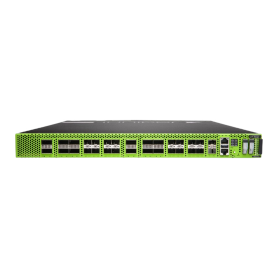
Chassis Physical Specifications for SRX4700 The SRX4700 Firewall has a 1-U form factor and can be installed in a standard 19-inch rack. Table 4: Physical Specifications of SRX4700 Model Height Width Depth Weight SRX4700 chassis 1.72 in. (4.37 cm) 17.28 in. (43.9 cm) 26.89 in. - Page 22 Figure 1: Front Panel Components of an SRX4700 Callout Component (Label on the Description Chassis) QSFP56-DD ports Two 400-Gigabit Ethernet (400 GbE) QSFP56-DD MACsec ports for network traffic QSFP28 ports Ten 100 GbE QSFP28 MACsec ports for network traffic SFP56 ports...
-
Page 23: Chassis Status Leds
To power off the firewall press and hold the button for 4 seconds Console port (CON) You can connect a laptop to the SRX4700 for CLI management. The port uses an RJ-45 serial connection and supports the RS-232 (EIA-232) standard... - Page 24 Callout Description SSD0 • Blinking green—The device is transferring data to or from the SSD storage device. • Solid red—The SSD storage device has failed. • Off—SSD storage device is not present on the device. STAT • Solid green—The device is operating normally.
-
Page 25: Management Port Leds
(Continued) Callout Description • Solid green—All HA links are available. • Solid yellow—Some HA links are unavailable. • Red—Device is inoperable due to a monitor failure. • Off—HA is disabled. SSD1 • Blinking green—The device is transferring data to or from the SSD storage device. -
Page 26: Network Port Leds
Solid green—A link is established. • Off—No link established. Activity (LED on the right) • Blinking green—There is link activity. • Off—No link activity. Network Port LEDs Each SRX4700 network port uses a single bicolored LED to indicate link status or a fault condition. - Page 27 The number next to the LED indicates the port number to which the LED belongs. All network port LEDs behave the same. Table 5 on page 20 describes the network port LEDs on SRX4700 Firewall, their colors and states, and the status that they indicate. Table 5: Network Port LEDs on SRX4700 Firewall...
-
Page 28: Chassis Rear Panel
Chassis Rear Panel Figure 2: Rear Panel Components of the AC Variant of SRX4700 Callout Component Description Fan modules Six airflow out (AFO) fan modules (5+1 redundancy). Five fan modules are required for proper airflow across the chassis internal components. The sixth fan module provides redundancy. -
Page 29: Cooling System And Airflow In Srx4700 Firewalls
SRX4700 Fan Module LEDs | 24 The cooling system in the SRX4700 firewalls consists of six fan modules. In addition to the fans, an internal fan in each PSU also cools the device components. We ship the SRX4700 is shipped with 5+1 redundant fan modules preinstalled in the rear panel. - Page 30 Airflow The SRX4700 firewall provides front-to-back airflow. The fan modules pull the air toward them through the front of the chassis and exhaust it out through the back of the chassis.
- Page 31 Figure 4: Airflow Through the SRX4700 Chassis SRX4700 Fan Module LEDs You can examine the LEDs on each fan module to check the status of the fans. 1. Fan Modules LEDs Table 7: Fan Module LEDs LED Color LED State...
-
Page 32: Srx4700 Power System
DC Power Cable Specifications | 35 The SRX4700 Firewall ships with two AC or two DC PSUs (1+1 redundancy) preinstalled in the rear panel of the chassis in slots labeled 0 and 1. These PSUs are hot-removable and hot-insertable field replaceable units (FRUs). -
Page 33: Srx4700 Ac Power Supply Unit
AC Power Supply Unit Electrical Specifications | 27 AC Power Supply Unit LED | 27 The SRX4700 firewall supports 2200-W AC PSUs that you can monitor using an inter-integrated circuit C) bus from the boot complex programmable logic device (boot CPLD). The PSUs directly plug into the connectors provided on the CPU board. - Page 34 Each AC PSU provides power to all components in the firewall. The two PSUs provide full power redundancy to the firewall. If one PSU fails or is removed, the second PSU balances the electrical load without interruption. The firewall reassesses the power required to support the firewall configuration and issues error messages if the available power is insufficient.
- Page 35 Figure 5: AC Power Supply Unit Components and LED Status LED AC inlet plug — — Ejector lever Handle — — Table 9: AC Power Supply Unit LED Label Color State Description STATUS Green Blinking PSU is in standby state (1Hz) Blinking PSU firmware is updating...
-
Page 36: Supported Ac Power Cords
NOTE: In North America, AC power cords must not exceed 4.5 m in length, to comply with National Electrical Code (NEC) Sections 400-8 (NFPA 75, 5-2.2) and 210-52 and Canadian Electrical Code (CEC) Section 4-010(3). The cords supplied with the switch are in compliance. Table 10: SRX4700 AC Power Cord Specifications Country/Region Electrical Plug Standards... - Page 37 (Continued) Table 10: SRX4700 AC Power Cord Specifications Country/Region Electrical Plug Standards Juniper Model Graphic Specifications Number China 250 VAC, 16 A, GB 2099 CBL-EX-PWR-C19- 50 Hz Europe (except Italy, 250 VAC, 16 A, CEE (7) 7 CBL-EX-PWR-C19- Switzerland, and...
- Page 38 (Continued) Table 10: SRX4700 AC Power Cord Specifications Country/Region Electrical Plug Standards Juniper Model Graphic Specifications Number Korea 250 VAC, 16 A, KC 8305 CBL-EX-PWR-C19- 50 Hz North America 250 VAC, 20 A NemaNEMA 6-20 CBL2-PTX-SP-US-N 50 Hz or 60 Hz...
-
Page 39: Srx4700 Dc Power Supply Unit
DC Power Supply Unit Electrical Specifications | 33 DC Power Supply Unit LEDs | 33 DC Power Circuit Breaker Requirements for the SRX4700 Firewall | 35 The DC PSU is a hot-removable and hot-insertable field-replaceable unit (FRU). You can install it without powering off the firewall or disrupting the firewall function. - Page 40 Handle Ejector lever — — DC inlet cable lug point — Each DC PSU provides power to all components in the firewall. The two PSUs provide full power redundancy to the firewall. If one PSU fails or is removed, the second PSU balances the electrical load without interruption.
- Page 41 Figure 6: DC Power Supply Unit Components and LED Handle Ejector lever — — Status LED DC inlet cable lug point — — Table 12: DC Power Supply Unit LED Label Color State Description STATUS Green Blinking PSU is in standby state. (1 Hz) Blinking PSU firmware is updating.
-
Page 42: Dc Power Cable Specifications
Description No DC power to both the PSUs. DC Power Circuit Breaker Requirements for the SRX4700 Firewall Each DC PSU has a single DC input (–48 VDC and return) that requires a dedicated circuit breaker. We recommend that you use a dedicated customer-site circuit breaker rated for 60 A (80 VDC), or as required by local code. - Page 43 Figure 7: DC Power Cable Lug CAUTION: Before you install the firewall, a licensed electrician must attach a cable lug to the grounding and power cables that you supply. A cable with an incorrectly attached lug can damage the firewall. DC Power Cable Specifications You must supply four DC power cables that meet the following specifications: 6 AWG (13 mm²) stranded wire, minimum 60 °C wire, or as permitted by local code.
-
Page 44: Site Planning, Preparation, And Specifications
C HAPTER Site Planning, Preparation, and Specifications IN THIS CHAPTER Site Guidelines and Requirements for SRX4700 | 38 SRX4700 Management Cable Specifications and Pinouts | 47 SRX4700 Network Cable and Transceiver Planning | 50... -
Page 45: Site Guidelines And Requirements For Srx4700
Site Guidelines and Requirements for SRX4700 IN THIS SECTION SUMMARY Site Preparation Checklist for SRX4700 | 38 The proper function of the SRX4700 depends on your meeting certain environmental requirements, Environmental Requirements and following site and wiring guidelines, and ensuring... -
Page 46: For More Information
(Continued) Table 13: Site Preparation Checklist Item or Task For More Information Performed by Date Locate sites to connect system grounding. Rack or Cabinet Verify that the rack or cabinet • Rack Requirements meets the minimum requirements for installing the router. •... -
Page 47: Environmental Requirements And Specifications For Srx4700
Environmental Requirements and Specifications for SRX4700 You must install the router in a rack or cabinet. You must house the router in a dry, clean, well- ventilated, and temperature-controlled environment. Follow these environmental guidelines: • Keep the site as dust-free as possible, because dust can clog air intake vents and filters, reducing the efficiency of the router cooling system. -
Page 48: General Site Guidelines
General Site Guidelines Efficient device operation requires proper site planning. You also need to ensure maintenance and proper layout of the equipment, rack or cabinet, and wiring closet. To plan and create an acceptable operating environment for your device and prevent environmentally caused equipment failures: •... -
Page 49: Rack Requirements For Srx4700
Electrical hazards as a result of power surges conducted over the lines into the equipment. Rack Requirements for SRX4700 You can mount the SRX4700 on four-post racks. The rack mounting kit (JNP-4P-TL-1RU-RMK) is shipped with the firewall. Table 16 on page 43 provides the rack requirements and specifications for SRX4700. - Page 50 Table 16: Rack Requirements and Specifications Rack Requirement Guidelines Rack type Use a four-post rack with bracket holes or hole patterns spaced at 1 U increments (1.75 in. or 4.45 cm). Ensure that the rack meets the size and strength requirements to support the weight. A U is the standard rack unit as defined in Cabinets, Racks, Panels, and Associated Equipment (document number EIA-310–D) published by the Electronics...
- Page 51 • Ensure that the rack is strong enough to support the weight of the device. A fully-configured SRX4700 with 2 PSUs weighs about 42 lb (19.1 kg). • Ensure that the spacing of rails and adjacent racks allows for proper clearance around the device and...
-
Page 52: Cabinet Requirements
(Continued) Table 16: Rack Requirements and Specifications Rack Requirement Guidelines Rack connection to building structure • Secure the rack to the building structure. • If earthquakes occur in your geographical area, secure the rack to the floor. • Secure the rack to the ceiling brackets and to wall or floor brackets for maximum stability. -
Page 53: Clearance Requirements For Airflow And Hardware Maintenance For Srx4700
A cabinet larger than the minimum required provides better airflow and reduces the chance of overheating. Clearance Requirements for Airflow and Hardware Maintenance for SRX4700 When planning the site for installing a SRX4700, follow these clearance requirements (see Figure 8 on page 47): •... -
Page 54: Srx4700 Management Cable Specifications And Pinouts
• DC NEBS GR-3160 recommends that you allow at least 30 in. (76.2 cm) in front of the rack or cabinet for chassis replacement and 24 in. (61 cm) in rear for component replacement. Figure 8: Clearance Requirements for Airflow and Hardware Maintenance for SRX4700 SRX4700 Management Cable Specifications and... -
Page 55: Srx4700 Cable Specifications For Console And Management Connections
SRX4700 Management Port Connector Pinouts You must use an RJ-45 connector to connect the 10/100/1000BASE-T management port (labeled MGMT) to a management device for out-of-band management. Table 18: Pinouts of the RJ-45 Management Port Connector on the SRX4700 Signal Description... -
Page 56: Srx4700 Console Port Connector Pinouts
(Continued) Table 18: Pinouts of the RJ-45 Management Port Connector on the SRX4700 Signal Description TRP1– Transmit/receive data pair 1 TRP2+ Transmit/receive data pair 2 TRP3+ Transmit/receive data pair 3 TRP3– Transmit/receive data pair 3 TRP2– Transmit/receive data pair 2... -
Page 57: Srx4700 Network Cable And Transceiver Planning
Calculating Power Budget and Power Margin for Fiber-Optic Cables | 53 Pluggable Transceivers and Cables Supported on SRX4700 Firewall You can find the list of transceivers and cables supported on SRX4700 routers and information about those transceivers and cables at the Hardware Compatibility Tool page for SRX4700. -
Page 58: Fiber-Optic Cable Signal Loss, Attenuation, And Dispersion
Juniper Networks. If you face a problem running a Juniper device that uses third-party optical modules or cables, JTAC may help you diagnose host-related issues if the observed issue is not, in the opinion of JTAC, related to the use of the third-party optical modules or cables. - Page 59 Single-mode fiber is so small in diameter that rays of light can reflect internally through one layer only. Interfaces with single-mode optics use lasers as light sources. Lasers generate a single wavelength of light, which travels in a straight line through the single-mode fiber. Compared with multimode fiber, single-mode fiber has a higher bandwidth and can carry signals for longer distances.
-
Page 60: Calculating Power Budget And Power Margin For Fiber-Optic Cables
TIP: You can use the Hardware Compatibility Tool to find information about the pluggable transceivers supported on your Juniper Networks device. To calculate the power budget and power margin, perform the following tasks: Calculate Power Budget for Fiber-Optic Cables To ensure that fiber-optic connections have sufficient power for correct operation, you need to calculate the link's power budget (P ), which is the maximum amount of power it can transmit. - Page 61 – LL greater than zero indicates that the power budget is sufficient to operate the receiver. Factors that can cause link loss include higher-order mode losses, modal and chromatic dispersion, connectors, splices, and fiber attenuation. Table 20 on page 54 lists an estimated amount of loss for the factors used in the following sample calculations.
- Page 62 The following sample calculation for an 8-km-long single-mode link with a P of 13 dB uses the estimated values from Table 20 on page 54. This example calculates LL as the sum of fiber attenuation (8 km @ 0.5 dB/km, or 4 dB) and loss for seven connectors (0.5 dB per connector, or 3.5 dB). The pP calculated as follows: –...
-
Page 63: Initial Installation And Configuration
IN THIS CHAPTER SRX4700 Firewall Installation Overview | 57 Unpack the SRX4700 | 57 Install the SRX4700 in a Rack | 59 Connect SRX4700 to External Devices | 69 Connect SRX4700 to Power | 71 Configure Junos OS on the SRX4700 | 81... -
Page 64: Srx4700 Firewall Installation Overview
SRX4700 | 58 Tools and Parts Required to Unpack the SRX4700 Firewall To unpack the SRX4700 and prepare for installation, you need the following tools: • Phillips (+) screwdriver, number 2 • A box cutter or packing knife to slice open the tape that seals the boxes... -
Page 65: Unpack An Srx4700
We ship the parts as per the configuration you order. If any part on the packing list is missing, contact your customer service representative or contact Juniper customer care from within the U.S. or Canada by telephone at 1-888-314-5822. For international-dial or direct-dial options in countries without toll-free numbers, see https:/ /www.juniper.net/support/... -
Page 66: Install The Srx4700 In A Rack
TL-1RU-RMK Rack Mount Kit on a Threaded- Hole 4-Post Rack | 63 You can mount the SRX4700 on a four-post rack or in a cabinet. Use the toolless rack mount kit shipped with the device. Complete these prerequisites before you mount the device: •... -
Page 67: Mount Your Device By Using The Jnp-4P-Tl-1Ru-Rmk Rack Mount Kit On A Square Hole 4-Post Rack
NOTE: Ensure that you support the rear of the chassis throughout the process of mounting the appliance on the rack. CAUTION: A qualified technician must verify that the rack or cabinet is strong enough to support the device's weight before mounting the device. Have the technician verify also that the rack or cabinet has adequate support at the installation site. - Page 68 Figure 9: Attach the Side Mounting Brackets 4. Assemble the mounting rails by sliding the rear floating rails into the front rails. Figure 10: Assemble the Mounting Rails 5. Install the mounting rails on the rack: a. Align the guide blocks of the rear mounting rails with the rear-post holes. Pull the rear mounting rails toward the front of the rack to lock the rails in place.
- Page 69 Figure 11: Install the Rear Mounting Rails b. Align the guide blocks of the front mounting rails with the front-post holes. Push the front mounting rails toward the rear of the rack to lock the rails in place. You will hear a distinct click sound when the latch locks into the corresponding rack holes.
-
Page 70: Mount Your Device By Using The Jnp-4P-Tl-1Ru-Rmk Rack Mount Kit On A Threaded-Hole 4-Post Rack
Figure 13: Slide the Device into the Rack 7. Tighten the two thumbscrews to secure the device. Figure 14: Tighten the Thumbscrews Mount your Device by Using the JNP-4P-TL-1RU-RMK Rack Mount Kit on a Threaded-Hole 4-Post Rack Ensure that you have the following tools and parts available: •... - Page 71 • Eight screws to attach the mounting rails to the rack posts—not provided. • A pair of side mounting brackets that attach to the chassis—provided with the rack mount kit. • A pair of mounting front and rear rails that attach to the rack posts—provided with the rack mount kit.
- Page 72 Figure 16: Removing the Guide Blocks from the Front Mounting Rail b. Remove the guide blocks from the rear mounting rail by loosening the screws and washers. Figure 17: Removing the Guide Blocks from the Rear Mounting Rail c. Slide the rear floating rails into the front rails. Figure 18: Assemble the Mounting Rails 5.
- Page 73 a. Insert the guide pin of the rear mounting rails into the rear-post holes. Pull the rear mounting rails toward the front of the rack to lock the rails in place. You will hear a distinct click sound when the latch locks into place.
- Page 74 Figure 21: Secure the Rear Mounting Brackets d. Visually ensure that the front and rear latches are locked into place on the mounting rails. The mounting rails should be securely installed on the rack. Figure 22: Mounting Rails Installed and Secured 6.
- Page 75 Figure 23: Slide the Device into the Rack 7. Tighten the two thumbscrews to secure the device. Figure 24: Tighten the Thumbscrews...
-
Page 76: Connect Srx4700 To External Devices
IN THIS SECTION Connect the SRX4700 to a Network for Out-of-Band Management | 69 Connect the SRX4700 to a Management Console Using an RJ-45 Connector | 70 Connect the SRX4700 to a Network for Out-of-Band Management Ensure that you have an Ethernet cable that has an RJ-45 connector at each end. -
Page 77: Connect The Srx4700 To A Management Console Using An Rj-45 Connector
Connect the SRX4700 to a Management Console Using an RJ-45 Connector Ensure that you have an Ethernet cable that has an RJ-45 connector at either end. You will also need the appropriate adapter (not provided) depending upon your console server or management console. -
Page 78: Connect Srx4700 To Power
Power Off the SRX4700 | 80 NOTE: To meet safety and electromagnetic interference (EMI) requirements and to ensure proper operation, you must connect the SRX4700 to an earth ground before you connect it to power. Tools and Parts Required to Ground and Connect the SRX4700 to Power To ground and to provide power to the firewall, you need the following tools and parts: •... -
Page 79: Connect Earth Ground To The Srx4700
• Electrostatic discharge (ESD) grounding wrist strap. Connect Earth Ground to the SRX4700 To ground the SRX4700 Firewall: Ensure that you have the following parts and tools available: •... - Page 80 Chassis ESD Point 2. Connect the grounding cable to a proper earth ground, such as the rack in which you will mount the firewall. 3. Place the grounding cable terminal attached to the grounding cable over the grounding point. Chassis grounding point 4.
-
Page 81: Connect Ac Power To The Srx4700
Connect AC Power to the SRX4700 The AC PSUs in an SRX4700 are hot-removable and hot-insertable field-replaceable units (FRUs). You can remove and replace the AC PSUs without powering off the firewall or disrupting its functions. - Page 82 1. Wrap and fasten one end of the ESD wrist strap around your bare wrist, and connect the other end of the strap to the ESD point on the firewall. 2. Locate the AC power cords shipped with the SRX4700; the cords have plugs appropriate for your geographical location. See "Supported AC Power Cords"...
-
Page 83: Connect Dc Power To The Srx4700
9. If the AC power source outlet has a power switch, set it to the on (|) position. Connect DC Power to the SRX4700 The DC power supply units (PSUs) in an SRX4700 are hot-removable and hot-insertable field- replaceable units (FRUs). You can remove and replace the DC PSUs without powering off the firewall or disrupting its functions. - Page 84 WARNING: Before performing the following procedure, ensure that you remove the power from the DC circuit. To ensure that all power is off, locate the circuit breaker on the panel board that services the DC circuit. Switch the circuit breaker to the OFF position (0), and tape the switch handle of the circuit breaker in the OFF position.
- Page 85 Figure 28: Install Heat-Shrink Tubing Verify that you have correctly labeled the DC power cables before making connections to the power supply. In a typical power distribution scheme where the return is connected to chassis ground at the battery plant, you can use a multimeter to verify the ohm output of the —48 V and return (RTN) DC cables to chassis ground.
- Page 86 Remove the nuts from the four terminals. Secure each power cable lug to the terminals with the nuts. Tighten the nuts on the power supply terminals until snug by using the screwdriver. Apply between 23 lbf-in. (2.6 Nm) to and 25 lbf-in. (2.8 Nm) of torque to the nuts.
-
Page 87: Power Off The Srx4700
12. Connect the power cables to the external DC power source. If the external DC power source has a switch, set it to the ON (|) position. Power Off the SRX4700 For a graceful shutdown, press and hold the power button for atleast 4 seconds. The firewall begins gracefully shutting down the operating system (OS) and then powers itself off. -
Page 88: Configure Junos Os On The Srx4700
View the Factory-Default Configuration of the SRX4700 | 84 We ship the SRX4700 Firewall with preinstalled Junos OS, which is ready to be configured when you power on the device. You can use the J-Web GUI, Juniper® Security Director (on-prem), Juniper®... -
Page 89: Configure The Srx4700 Using Juniper® Security Director Cloud
Configure the SRX4700 using Juniper® Security Director Cloud Juniper® Security Director Cloud is a cloud-based software-as-a-solution (SaaS) portal that helps you securely migrate your network to a Secure Access Service Edge (SASE) architecture. Follow the instructions in the... -
Page 90: Configure Root Authentication And The Management Interface From The Cli
NOTE: After you have completed the initial configuration, you can connect your device to a network for out-of-band management as described in "Connect the SRX4700 to a Network for Out-of-Band Management" on page Configure Root Authentication and the Management Interface from the You must perform the initial configuration of the device through the console port. -
Page 91: Factory-Default Configuration Of The Srx4700
• Source Network Address Translation (NAT) is configured on the trust zone. If the current active configuration fails, you can use the load factory-default command to revert to the factory-default configuration. View the Factory-Default Configuration of the SRX4700 To view the factory-default configuration of the firewall using the CLI:... - Page 92 1. Log in as the root user and provide your credentials. 2. View the list of default configuration files: root@srx4700>file list /etc/config 3. View the required default configuration file. root@srx4700>file show /etc/config/ config-file-name...
-
Page 93: Maintain Components
C HAPTER Maintain Components IN THIS CHAPTER Routine Maintenance Procedures for the SRX4700 Firewall | 87 SRX4700 Cooling System Maintenance | 88 SRX4700 Power Supply Maintenance | 91 SRX4700 SSD Maintenance | 100... -
Page 94: Routine Maintenance Procedures For The Srx4700 Firewall
Routine Maintenance Procedures for the SRX4700 Firewall IN THIS SECTION Purpose | 87 Action | 87 Purpose For optimum firewall performance, perform preventive maintenance procedures regularly. Action • Inspect the installation site for moisture, loose wires or cables, and excessive dust. -
Page 95: Srx4700 Cooling System Maintenance
Install the Fan Module in the SRX4700 | 90 The SRX4700 has six independent, hot-removable and hot-insertable field-replaceable fan modules at the rear of the chassis. For optimum cooling, verify the condition of the fan modules. -
Page 96: Remove The Fan Module From The Srx4700
3 minutes 40 °C 2 minutes Remove the Fan Module from the SRX4700 CAUTION: Do not remove a fan unless a replacement fan is available. To remove a fan module: 1. Wrap and fasten one end of the ESD grounding strap around your bare wrist, and connect the other end of the strap to one of the ESD points on the chassis. -
Page 97: Install The Fan Module In The Srx4700
5. Place the fan module in the antistatic bag or on the antistatic mat. Install the Fan Module in the SRX4700 To install a fan module: 1. Wrap and fasten one end of the ESD grounding strap around your bare wrist, and connect the other end of the strap to one of the ESD points on the chassis. -
Page 98: Srx4700 Power Supply Maintenance
Maintain the Power Supplies | 91 Maintaining an SRX4700 includes removing a failed power supply unit (PSU) and installing a functional Replace an AC PSU on the SRX4700 | 92 PSU. Replace a DC PSU on the SRX4700 | 95... -
Page 99: Replace An Ac Psu On The Srx4700
CAUTION: Do not mix AC and DC PSUs in the same chassis. Replace an AC PSU on the SRX4700 IN THIS SECTION Remove an AC PSU from the SRX4700 | 93 Install an AC PSU in the SRX4700 | 94... -
Page 100: Remove An Ac Psu From The Srx4700
The SRX4700 rear panel has two AC PSUs, which are hot-removable and hot-insertable field- replaceable units (FRUs). You can remove and replace the PSUs without powering off the SRX4700 or disrupting the firewall functions. Ensure that you have the following parts and tools: •... -
Page 101: Install An Ac Psu In The Srx4700
6. Pull the PSU straight out of the chassis. Install an AC PSU in the SRX4700 To install an AC PSU: 1. Wrap and fasten one end of the ESD grounding strap around your bare wrist, and connect the other end of the strap to one of the ESD points on the chassis. -
Page 102: Replace A Dc Psu On The Srx4700
Install a DC PSU in the SRX4700 | 97 The rear panel of the SRX4700 has two DC PSUs, which are hot-removable and hot-insertable field- replaceable units (FRUs). You can remove and replace the PSUs without powering off the SRX4700 or disrupting the firewall functions. -
Page 103: Remove A Dc Psu From The Srx4700
Remove a DC PSU from the SRX4700 Before you remove a PSU, be aware of the following: CAUTION: Avoid leaving the PSU slot empty for more than 30 minutes when the device is operational. For proper airflow, you must place the PSU in the chassis. Always cover the empty PSU slot with a blank panel. -
Page 104: Install A Dc Psu In The Srx4700
Carefully move the power cables out of the way. 10. Place the terminal block cover on and tighten the screw. Install a DC PSU in the SRX4700 WARNING: Before you perform DC power procedures, ensure there is no power to the DC circuit. - Page 105 Using both hands, slide the DC PSU straight into the chassis until the PSU is fully seated in the chassis slot. The PSU faceplate must align with any adjacent PSU faceplate installed in the PSU slot. Using a screwdriver (anticlockwise), unscrew the nut on top of the terminal block and remove the terminal block cover.
- Page 106 a. Secure the positive (+) DC source power cable lug to the RTN (return) terminal. b. Secure the negative (–) DC source power cable lug to the –48V/-60V (input) terminal. CAUTION: Ensure that each power cable lug seats flush against the surface of the terminal block as you are tightening the nuts.
-
Page 107: Srx4700 Ssd Maintenance
Replace the 1T and 2T SSDs from the SRX4700 Firewall | 103 The two SSDs installed in the SRX4700 Firewall are field-replaceable units (FRUs). SSDs are not hot- swappable, so you need to power off the firewall to replace an SSD. -
Page 108: Remove An Ssd From The Srx4700 Firewall
• SSD to replace Remove an SSD from the SRX4700 Firewall You need to power off the SRX4700 Firewall to remove an SSD. 1. Wrap and fasten one end of the ESD grounding strap around your bare wrist, and connect the other end of the strap to one of the ESD points on the chassis. -
Page 109: Install An Ssd In The Srx4700 Firewall
2. Slide the SSD gently into its slot until it is fully seated. Press the SSD front stopper to lock the SSD into its slot. Replace the 1T SSD in the SRX4700 Firewall You need to power off the SRX4700 Firewall to replace the 1T SSD (primary SSD). NOTE: 1T SSD must be installed only in slot... -
Page 110: Replace The 2T Ssd In The Srx4700 Firewall
6. Issue the show vmhost hardware CLI command to verify the details of the SSDs. Replace the 2T SSD in the SRX4700 Firewall You need to power off the SRX4700 Firewall to replace the 2T SSD (secondary SSD). NOTE: 2T... - Page 111 2. Remove the 1T SSD from the slot SSD0 and 2T SSD from the slot SSD1. See, "Remove an SSD from the SRX4700 Firewall" on page 101. 3. Install the replacement 1T SSD in slot SSD0 and 2T SSD in slot SSD1. See, "Install an SSD in the...
-
Page 112: Troubleshoot Hardware
C HAPTER Troubleshoot Hardware IN THIS CHAPTER Troubleshoot the SRX4700 | 106... -
Page 113: Troubleshoot The Srx4700
CLI to troubleshoot Junos OS, see the appropriate Junos OS configuration guide. • JTAC—If you need assistance during troubleshooting, you can contact the Juniper Networks Technical Assistance Center (JTAC) by using the Web or by telephone. If you encounter software problems, or problems with hardware components not discussed here, contact JTAC. - Page 114 Replace the failed fan module to avoid failure of the other fan modules. • Open a support case using the Case Manager link at https:/ /www.juniper.net/ support/ or call 1-888-314-5822 (toll-free within the United States and Canada) or 1-408-745-9500 (from outside the United States).
- Page 115 (Continued) Table 23: Alarms for Firewall Chassis Components Component Alarm Conditions Action Alarm Severity Missing fan module Install the missing fan module. Red (major) Fan overspeeding Yellow (minor) • Check whether the fan is spinning at a speed higher than the configured speed. •...
- Page 116 Check whether the voltage the PSU of the power source is in the operating range. • Open a support case using the Case Manager link at https:/ /www.juniper.net/ support/ or call 1-888-314-5822 (toll-free within the United States and Canada) or 1-408-745-9500 (from outside the United States).
- Page 117 PSU internal devices Red (major) • Replace the PSU. failure. • Open a support case using the Case Manager link at https:/ /www.juniper.net/ support/ or call 1-888-314-5822 (toll-free within the United States and Canada) or 1-408-745-9500 (from outside the United States).
-
Page 118: Troubleshoot The Srx4700 Firewall Cooling System
Check whether the USB slot is receiving power. • Check for the port-level failures. • Check whether the USB is faulty, and replace it if it is faulty. Troubleshoot the SRX4700 Firewall Cooling System IN THIS SECTION Problem | 112 Solution | 112... -
Page 119: Troubleshoot The Srx4700 Firewall Power System
• The firewall temperature exceeds the “temperature warm” threshold (minor alarm). • The temperature of the firewall exceeds the maximum (“temperature hot”) threshold (major alarm and automatic shutdown of the power supplies). Troubleshoot the SRX4700 Firewall Power System IN THIS SECTION Problem | 113... - Page 120 LEDs glow steadily. For more information about PSU LEDs, see "SRX4700 Power System" on page • Use the CLI show chassis environment pem command to check the status of the installed PSUs. If a PSU is not functioning normally, perform the following tasks to diagnose and correct the problem: •...
-
Page 121: Reboot The Firewall Using The Reset Button
, or call 1-888-314-JTAC (within the United States) or 1-408-745-9500. Reboot the Firewall Using the RESET Button To troubleshoot the firewall, you might need to reboot it. To reboot the SRX4700 Firewall, press and hold the RESET button for less than 5 seconds. -
Page 122: Contact Customer Support And Return The Chassis Or Components
C HAPTER Contact Customer Support and Return the Chassis or Components IN THIS CHAPTER Return an SRX4700 Chassis or a Component | 116... -
Page 123: Return An Srx4700 Chassis Or A Component
How to Return a SRX4700 Chassis or a Component for Repair or Replacement If you need to return a firewall or hardware component to Juniper Networks for repair or replacement, follow this procedure: 1. Determine the serial number of the chassis if you need to return the firewall. If you need to return one or more components, determine the serial number for each component. -
Page 124: Locate The Serial Number On A Srx4700 Chassis Or Component
To list the firewall and firewall components and their serial numbers, enter the CLI command show chassis hardware extensive. Locate the Chassis Serial Number ID Label on an SRX4700 Firewall The serial number ID label is located on the top cover of the chassis on SRX4700 firewalls. -
Page 125: Locate The Serial Number Id Labels On Frus In An Srx4700
• Fan module—The serial number ID label is on the side of the fan module. 1. Serial number ID label • PSU—The PSUs installed in an SRX4700 are FRUs. You must remove each FRU from the firewall chassis to see the FRU serial number ID label. - Page 126 1. Serial number ID label • DC PSU—The serial number ID label is on the top of the DC PSU. 1. Serial number ID label • SSD—The serial number ID label is on the side of the SSD. 1. Serial number ID label...
-
Page 127: Contact Customer Support To Obtain A Return Material Authorization
Contact Customer Support to Obtain a Return Material Authorization If you need to return a device or hardware component to Juniper Networks for repair or replacement, obtain an RMA number from JTAC. You must obtain an RMA number before you attempt to return the component. -
Page 128: Pack An Srx4700 Firewall Or Component For Shipping
Pack the Firewall for Shipping | 121 Pack the Firewall Components for Shipping | 122 If you are returning an SRX4700 firewall or component to Juniper Networks for repair or replacement, pack the item as described in this topic. Before you pack the firewall or component, ensure that you have: •... -
Page 129: Pack The Firewall Components For Shipping
• An ESD grounding strap—not provided • Antistatic bag—not provided If you need to transport the firewall to another location or return the firewall to Juniper Networks, you need to pack the firewall securely in its original packaging to prevent damage during transportation. - Page 130 CAUTION: Do not stack firewall components. Return individual components in separate boxes if they do not fit together on one level in the shipping box. To pack the firewall components: • Place individual components in antistatic bags. • Use the original packing materials if they are available. If the original packing materials are not available, ensure the component is adequately packed to prevent damage during transit.
-
Page 131: Safety And Compliance Information
C HAPTER Safety and Compliance Information IN THIS CHAPTER Safety Information for SRX4700 | 125 Compliance Standards for SRX4700 Firewalls | 125 Compliance Statements for EMC Requirements for SRX4700 Firewall |... -
Page 132: Safety Information For Srx4700
Networks products. Follow the guidelines provided in the guide to reduce the likelihood of personal injury, equipment damage, and damage to surrounding areas. Along with the information provided in the Juniper Networks Safety Guide, you must read and understand the specific safety information for SRX4700 provided in this hardware guide. - Page 133 • EMC • FCC 47 CFR Part 15 • ICES-003 / ICES-GEN • BS EN 55032 • BS EN 55035 • EN 300 386 V1.6.1 • EN 300 386 V2.2.1 • BS EN 300 386 • EN 55032 • CISPR 32 •...
-
Page 134: Compliance Statements For Nebs
• You must provision a readily accessible device outside of the equipment to disconnect power. The device must also be rated based on local electrical code practice. • For Juniper Networks systems with AC power supplies, an external surge protective device (SPD) must be used at the AC power source. -
Page 135: Compliance Statements For Emc Requirements For Srx4700 Firewall
Compliance Statements for EMC Requirements for SRX4700 Firewall IN THIS SECTION Canada | 128 Taiwan | 129 European Community | 129 Israel | 130 Japan | 130 Korea | 130 United States | 131 FCC Part 15 Statement | 131... -
Page 136: European Community
aware that compliance with the above conditions might not prevent degradation of service in some situations. Repairs to certified equipment should be made by an authorized Canadian maintenance facility designated by the supplier. Any repairs or alterations made by the user to this equipment, or equipment malfunctions, might give the telecommunications company cause to request the user to disconnect the equipment. - Page 137 Israel The preceding translates as follows: Warning: This product is Class A. In residential environments, the product may cause radio interference, and in such a situation, the user may be required to take adequate measures. Japan The preceding translates as follows: This is a Class A device.
-
Page 138: Fcc Part 15 Statement
The preceding translates as follows: This equipment is Industrial (Class A) electromagnetic wave suitability equipment and seller or user should take notice of it, and this equipment is to be used in the places except for home United States The device has been tested and found to comply with the limits for a Class A digital device, pursuant to Part 15 of the FCC Rules. -
Page 139: Compliance Statement For Argentina
EMC Requirements for Japan The preceding translates as follows: This is a Class A product. In a domestic environment this product may cause radio interference in which case the user may be required to take adequate measures. VCCI-A Compliance Statement for Argentina EQUIPO DE USO IDÓNEO.
Need help?
Do you have a question about the SRX4700 and is the answer not in the manual?
Questions and answers