Little Giant VCMX-20, VCMX20UL, 554520 Manual
- Instruction sheet (16 pages) ,
- Installation manual (9 pages) ,
- Owner's manual (25 pages)
Advertisement
INTRODUCTION
This instruction sheet provides you with the information required to safely own and operate your Little Giant pump. Retain these instructions for future reference.
The Little Giant pump you have purchased is of the highest quality workmanship and material, and has been engineered to give you long and reliable service. Little Giant pumps are carefully tested, inspected, and packaged to ensure safe delivery and operation. Please examine your pump carefully to ensure that no damage occurred during shipment. If damage has occurred, please contact the place of purchase. They will assist you in replacement or repair, if required.
READ THESE INSTRUCTIONS CAREFULLY BEFORE ATTEMPTING TO INSTALL, OPERATE, OR SERVICE YOUR LITTLE GIANT PUMP. KNOW THE PUMP'S APPLICATION, LIMITATIONS, AND POTENTIAL HAZARDS. PROTECT YOURSELF AND OTHERS BY OBSERVING ALL SAFETY INFORMATION. FAILURE TO COMPLY WITH THESE INSTRUCTIONS COULD RESULT IN PERSONAL INJURY AND/OR PROPERTY DAMAGE!
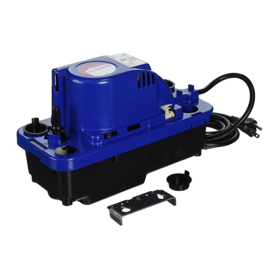
DESCRIPTION
The Little Giant VCMX-20 automatically removes condensation from air conditioners and high-efficiency gas furnaces. A float/switch mechanism turns the pump on when approximately 1.6" of water collects in its tank, and turns the pump off when the tank drains to approximately 1.2". A safety overflow switch activates when water in the tank rises to approximately 2.2", turning off the thermostat or turning on an alarm (depending upon wiring configuration).
INSTALLATION


Do not install this pump where it can be splashed or sprayed.
Do not use this pump inside air plenums.
- Carefully unpack the pump. Using the enclosed mounting bracket, mount the pump either on the side of the air conditioner/furnace or on a nearby wall. (See Figures 10 and 11 for pump dimensions.) The tank has a mounting slot on each side so it can be positioned either way (Figure 1). Ensure that the pump is level and the inlet is below the coil drain. Conduit fittings are not compatible with the plastic pump housing.
Pumps with an anti-sweat sleeve use a different mounting bracket, but the mounting location holes are the same and the brackets are interchangeable.
If mounting the pump on a flat surface, install the enclosed 4 rubber feet onto the bottom of the tank.

- Fully insert the enclosed check valve into the discharge line, ensuring that the O-ring and discharge line are free of debris (Figure 2).
Figure 2
![]()
- Insert the check valve into the pump discharge hole and twist it by hand 1/4 turn (Figure 3).
Figure 3
![]()
- Check to ensure that the valve is securely locked into position (Figure 4).
Figure 4
![]()


ELECTRICAL CONNECTIONS
All wiring must be performed by a qualified service technician. Check local electrical and building codes before installation. The installation must be in accordance with their regulations as well as the most recent National Electrical Code (NEC).
- Shut off electrical power at fuse box before making any connections. All wiring must comply with local codes.
- Line voltage: Connect power cord to line voltage specified on motor and nameplate. Power cord must be connected to a constant source of power (not a fan or other device that runs intermittently). If power cord does not have a plug, wiring is as follows: green (or green/yellow) is ground, black (or brown) is line, and white (or blue) is neutral.
- Safety switch: The safety overflow switch should be connected to a Class-II low voltage circuit. To control a thermostatic circuit the COM and NO connections from the safety switch are to be wired in series with the low voltage thermostat circuit to shut down the heating/AC circuit. The COM and NC switch contacts may be used to actuate a low-voltage alarm circuit (connected in series) if the heating/cooling system can not be disrupted. The safety switch comes from the factory with leads connected to the COM and NO switch terminals.
NOTE: When installing or replacing the safety switch, make sure that it is positioned between the two ribs on the motor cover (Figure 5).
For hook-up of NC circuits see Figure 5.

- If fused plug is used on 230V units, a 1.0 amp fuse is recommended.

PIPING
- Run an inlet line (flexible tubing or pipe) from the evaporator drain into one of the three drain holes, ensuring that the line is sloped downward to allow gravity flow. Cut the inlet line at an angle where it will enter the tank, then put the line into the tank 1 to 2 inches to ensure that it will not interfere with proper float operation.
- The discharge line (Figure 6) should be flexible tubing secured with a hose clamp (not provided) or pipe (3/8 inch I.D. maximum to prevent excessive flow back to unit). From the pump, extend the discharge line straight up as high as necessary (but not above the head/GPH of the pump). From this high point, slope the discharge line down slightly to a point above the drain, then turn down and extend to a point below or approximately level with the bottom of the pump. This will give a siphoning effect, which will improve the efficiency of the pump and will, in most cases, eliminate the need for a check valve. If it is not possible to slope the discharge line down, make an inverted U-trap directly above the pump at the highest point.


SERVICE INSTRUCTIONS
Inspect and service the pump at least once a year.
NOTE: This pump is equipped with a ¼-turn check valve, which can be easily disconnected from the pump during maintenance/cleaning. The discharge line (and the condensate in the line) can remain while the check valve is unlocked and removed.
- Disconnect the pump from the power source.
- To access the tank, float, or intake screen for cleaning, lightly squeeze the tank walls to release the latch (Figure 7), then grab and raise the motor cover. (The motor cover hinges on the opposite end of the tank.)

- Be sure the floats move freely. Clean as necessary.
- Clean the tank with warm water and mild soap.
- Check the inlet and discharge lines, cleaning as necessary. Be sure there are no kinks in the lines that would inhibit flow.
- Close the motor cover and reconnect the pump to the power source.

TESTING
- Turn on power.
- Press lightly on the external test/run lever to engage the motor (Figure 8).
Figure 8


Figure 9

| ITEM NO. | PART NO. | DESCRIPTION | 554520 VCMX-20UL | 554530 VCMX-20ULS | 554550 VCMX-ULST | 554542 VCMX-20ULS-C | 554521 VCMX-20UL | 554531 VCMX-20ULS |
| 1 | 154390 | Tank, black, polypropylene | 1 | 1 | 1 | 1 | 1 | 1 |
| 2 | 925047 | Feet, rubber (4 pack) | 1 | 1 | 1 | -- | 1 | 1 |
| 3 | 154425 | Cover, motor, blue, ABS | 1 | 1 | 1 | 1 | 1 | 1 |
| 4 | 154724 | Check valve, 3/8" | 1 | 1 | 1 | 1 | 1 | 1 |
| 5 | 154039 | Strain relief | 1 | 1 | 1 | 1 | 1 | 1 |
| 6 | 154460 | Float arm assembly | 1 | 1 | 1 | 1 | 1 | 1 |
| 7 | 902434 | Screw, tapping 8-18 x 3/4" | 6 | 6 | 6 | 6 | 6 | 6 |
| 8 | 929602 | Plug, drain hole | 2 | 2 | 2 | 2 | 2 | 2 |
| 9 | 154455 | Pin, pivot, float | 1 | 1 | 1 | 1 | 1 | 1 |
| 10 | 599136 | Safety switch assembly, 10" | -- | 1 | 1 | 1 | -- | 1 |
| 11 | 944320 | Tubing, 3/8" ID x 20' length (not shown) | -- | -- | 1 | -- | -- | -- |
| 12 | 599138 | Anti-sweat sleeve and bracket | -- | -- | -- | 1 | -- | -- |
| 13 | 154483 | Bracket, tank | 1 | 1 | 1 | -- | 1 | 1 |
Figure 10
Models with vibration-dampening feet and standard bracket

Figure 11
Models with anti-sweat sleeve and bracket

SAFETY GUIDELINES

- Do not use to pump flammable or explosive fluids such as gasoline, fuel oil, kerosene, etc. Do not use in explosive atmospheres. Pump should be used with liquids compatible with pump component materials.
- Do not handle pump with wet hands or when standing on a wet or damp surface, or in water. This pump is supplied with a grounding conductor and/or grounding type attachment plug. To reduce the risk of electrical shock, be certain that it is connected to a properly grounded grounding type receptacle.
- In any installations where property damage and/or personal injury might result from an inoperative or leaking pump due to power outages, discharge line blockage, or any other reason, a backup system(s) and/or alarm should be used.
- Support pump and piping when assembling and when installed. Failure to do so may cause piping to break, pump to fail, motor bearing failures, etc.
Documents / ResourcesDownload manual
Here you can download full pdf version of manual, it may contain additional safety instructions, warranty information, FCC rules, etc.
Advertisement


Need help?
Do you have a question about the VCMX-20 and is the answer not in the manual?
Questions and answers