Little Giant 5-MSP Series, 505000, 506160 - Pump Manual
- Instruction sheet (4 pages) ,
- Introduction (4 pages) ,
- User manual (2 pages)
Advertisement
WRSC-6 USER MANUAL
INTRODUCTION
Little Giant 6-CIA-ML 115 Volt, 1/3 HP, 2760 GPH Cast Iron Submersible Sump Pump with Integral Low Level Diaphragm Switch, Blue, 506160
This instruction sheet will provide you with information required to safely own and operate your Little Giant WRSC-6 kit. This unit is designed to pump wastewater from laundry trays, washing machines, sinks, or dehumidifiers. It is not designed to pump raw sewage, fluids other than water, or fluids with solids. The inlet screen will remove many solids over 1/8" diameter, but large amounts of solids can clog screen and result in pump failure. Maximum fluid temperature is 125°F. Unit is designed to fit under most sinks so in many cases it is not necessary to recess the unit into the floor.
This instruction sheet covers the standard models in this pump series. This form is applicable to other models in this series not listed by catalog number in the replacement parts list section of this pamphlet. If the catalog number of your pump is not listed in the replacement parts section, then exercise caution when ordering replacement parts. Always give the catalog number of your pump when ordering replacement parts.
The Little Giant unit you have purchased is of the highest quality workmanship and material. It has been engineered to give you long and reliable service.
Little Giant pumps are carefully packaged, inspected, and tested to ensure safe operation and delivery. When you receive your pump, examine it carefully to determine that there are no broken or damaged parts that may have occurred during shipment. If damage has occurred, make notation and notify the firm where you purchased the pump. They will assist you in replacement or repair, if required.
READ INSTRUCTIONS CAREFULLY BEFORE ATTEMPTING TO INSTALL, OPERATE OR SERVICE THE LITTLE GIANT PUMP. KNOW THE PUMP APPLICATION, LIMITATIONS, AND POTENTIAL HAZARDS. PROTECT YOURSELF AND OTHERS BY OBSERVING ALL SAFETY INFORMATION. FAILURE TO COMPLY WITH INSTRUCTIONS COULD RESULT IN PERSONAL INJURY AND/OR PROPERTY DAMAGE! RETAIN INSTRUCTIONS FOR FUTURE REFERENCE.
ELECTRICAL CONNECTIONS


- Check the pump label for proper voltage required. Do not connect to voltage other than that shown.
![]()
If pump is supplied with a 3-prong electrical plug, the third prong is to ground the pump to prevent possible electrical shock hazard. DO NOT REMOVE the third prong from the plug. A separate branch circuit is recommended. Do not use an extension cord. Do not cut plug from the cord. If the plug is cut or the cord is shortened, then this action will void the warranty.- If the cord is equipped with stripped lead wires, such as on 230 V models, be sure that the lead wires are connected to a power source correctly. The (green/ yellow) wire is the ground. The (blue or white) and the (brown or black) are live.
CONSULT INSTRUCTION SHEET ILLUSTRATIONS FOR PROPER ASSEMBLY AND DISASSEMBLY OF YOUR LITTLE GIANT PUMP. - Check local electrical and building codes before installation. The installation must be in accordance with their regulations as well as the most recent National Electrical Code (NEC).
- Plug into a grounded receptacle with vent tube pointed down. Vent tube must remain unobstructed for proper pump operation.
- If installed in basement, plug connection should be four feet or more above floor, especially if basement floods. Be sure electrical connections cannot be reached by rising water. Under no circumstances should outlet box or receptacle be located where it may become flooded or submerged by water.

OPERATION
- Determine proper location for unit. Unit should be located so that inlet is gravity-fed. Unit will not draw water up from a lower level. Position and level basin. Keep basin away from any item that could puncture basin. Position selected should be convenient to inlet, discharge and vent piping and electrical supply.
- Plumb inlet. Using proper adapter, plumb discharge to basin cover fitting. Use a P-trap and a union next to the basin. Use pipe joint compound and hand tighten only on plastic fittings. A 1-1/2" MNPT x 2" slip pipe adapter is provided if a 2" inlet is required. See "Typical Installation." (Figure 2)

- Plumb discharge. Using proper adapter, plumb discharge to basin cover fitting. Use a swing check valve as close as possible to top of basin cover and union. Be sure check valve is installed in proper flow direction. If check valve is installed backwards, no water will flow out of unit. Be sure discharge piping is sealed with pipe joint compound and that lift height of pump is not exceeded. Hand tighten only on plastic fitting. A 1-1/2" MNPT x 2" slip pipe adapter is provided if a 2" discharge is required.
- Plumb vent. Plumb vent using 2" threaded pipe to fitting in basin cover. Use pipe joint compound on threads and hand tighten only on plastic fittings. The basin must be vented in accordance with state and local codes. A 2" MNPT x 1-1/2" Slip pipe adapter is provided if a 1-1/2" vent is required.
THIS UNIT WILL NOT OPERATE WITHOUT PROPER VENTING.


Do not use a mechanical vent with this product. A mechanical vent will cause improper operation of the automatic switch.
- Test Unit. Connect power cord to electrical supply as stated in ELECTRICAL CONNECTIONS. Secure power cord to piping with ties or tape. Fill unit with water through inlet. Pump should turn on with 4" to 7" (10.2 - 17.8 cm) of water in tank, and turn off when 1½" to 3½" (3 - 8 cm) of water is left in tank. See Pump Troubleshooting Guide if problems occur.
SPECIFICATIONS
| Model No. | Catalog No. | Volts | Hertz | Amps | Watts | Gallons per hour (GPH) at ht. | Shutoff (FT.) | PSI Kg/cm2 | |||
| S | R | 5' | 10' | 15' | |||||||
| WRSC-6 | 506065 | 115 | 60 | 13 | 9 | 720 | 2750 | 1750 | 750 | 18 | 7.8 |
| WRSC-6 | 506066 | 230 | 50 | 7 | 5 | 720 | 2580 | 1050 | — | 12 | 5.2 |
SERVICE INSTRUCTIONS
MAKE CERTAIN THE UNIT IS DISCONNECTED FROM THE POWER SOURCE BEFORE ATTEMPTING TO SERVICE OR REMOVE ANY COMPONENT!
- To clean inlet filter remove the 4 cover plate screws (21), cover plate (19), seal ring (item 28), and screen (item 27). Clean inlet screen using a mild detergent and water. Examine o-ring and if deformed, replace with new o-ring. See replacement parts list.
- Sediment may build up in basin causing pump to operate improperly. Remove 10 1/4-20 screws (item 21) from cover. Remove cord grommet and loosen cords to allow slack and then remove cover.
Remove pump and clean basin using a mild detergent and water. Reassemble in reverse order. Torque screws (item 21) 18–20 in–lbs. - If pump alignment plate is removed, it must be reinstalled per plate alignment diagram (Figure 1).
Position the alignment plate inside the basin as shown. This will position the mounting holes properly when installing the basin cover. Any other position will prevent assembly of cover.

- Sediment or lint can clog pump and cause improper operation. If necessary, remove pump and pull off the pressed-in screen, clean using a mild detergent and water, and reinstall. Plastic pump base may also be removed to clean around impeller and inside base. Remove the six base screws and clean base using a mild detergent and water. Do not remove impeller. When reinstalling base, be sure seal ring is seated properly in groove and torque screws to 12-17 in.-lbs. See pump manual for other information. For any other pump repair, return the pump to a Little Giant authorized service center.
- This unit is permanently lubricated. Oiling is not required. Do not, in any case, open the sealed portion of the unit or remove housing screws.
- Remove screws (item 4) that hold base to volute and clean impeller and volute passage. Do not use strong solvents on impeller.
- Be sure impeller turns freely after cleaning. WARNING: DO NOT REMOVE IMPELLER. REMOVAL OF IMPELLER REQUIRES SPECIAL TOOLS AND IS TO BE DONE ONLY BY AN AUTHORIZED SERVICE CENTER.
- When reinstalling base, be sure seal ring is seated properly in groove and torque screws (item 4) to 10–15 in.–lbs.
- DO NOT REMOVE MOTOR HOUSING COVER. WARRANTY IS VOID IF MOTOR HOUSING COVER, IMPELLER OR SEALS HAVE BEEN REMOVED. ANY REPAIR ON MOTOR MUST BE DONE BY AN AUTHORIZED LITTLE GIANT SERVICE CENTER.

TROUBLESHOOTING INFORMATION
| PROBLEM | PROBABLE CAUSES | CORRECTIVE ACTIONS |
The unit will not shut offNote: Before troubleshooting automatic control check to see that pump operates on manual control. To do this, create slight vacuum on breather tube (near plug), then close off tube with thumb, plug into wall outlet. If pump works, proceed to check switch; if not, fault is in pump or power supply. | Diaphragm switch. | Replace switch. |
| Weak or hardened rubber diaphragm. | Replace rubber diaphragm. | |
| Plugged vent tube. | Clear vent tube of any obstructions. | |
| Dirt or sediment lodged between retainer ring and rubber diaphragm causing contacts to remain closed. | Clean area around rubber diaphragm. | |
| Pump is air locked. | Shut power off for approximately 1 minute, then restart. Repeat several times to clear air from pump. If system includes a check valve, a 3/16" hole should be drilled in discharge pipe approximately 2" above discharge connections. | |
| Liquid inflow matches pump capacity. | Larger pump required. | |
| Defective switch. | Disconnect switch, check w/ohmmeter, Open-infinitive resistance, closed-zero. | |
| Loose connection in level control wiring. | Check control wiring. | |
The unit runs but does not discharge liquid | Check valve installed backwards. | Check flow indicating arrow on check valve body to insure it is installed properly. |
| Check valve stuck or plugged. | Remove check valve and inspect for proper operation. | |
| Lift too high for pump. | Check rating table. | |
| Inlet to impeller plugged. | Pull pump and clean. | |
| Pump is air locked. | (See corrective action above.) | |
The unit does not deliver rated capacity | Lift too high for pump | Check rated pump performance. |
| Low voltage, speed too slow. | Check for proper supply voltage to make certain it corresponds to nameplate voltage. | |
| Impeller or discharge pipe is clogged. | Pull pump and clean. Check pipe for scale or corrosion. | |
| Impeller wear due to abrasives. | Replace worn impeller. |
REPLACEMENT PARTS LIST

Figure 3.
| ITEM NO. | PART NO. | DESCRIPTION | QTY. |
| 1 | 108101 | Handle, pump | 1 |
| 2 | 928004 | Seal ring | 1 |
| 3 | 108034 | Pump base, manual, blue | 1 |
| 4 | 909021 | Screw/washer #10-24 x 1/2" | 5 |
| 5 | 108082 | Screen, intake | 1 |
| 6 | 928028 | Seal ring | 1 |
| 7 | 108051 | Housing assemby, automatic, 8' (115v) | 1 |
| 7 | 108052 | Housing assemby, automatic, 8' (230v) | 1 |
| 8 | 108202 | Bracket, switch | 1 |
| 9 | 951961 | Lead wire assembly | 1 |
| 10 | 924001 | O-ring, Buna-N, 2-007 | 2 |
| 11 | 950322 | Switch, miniature | 1 |
| 12 | 901529 | Screw, machine #10–24 x 1/4" | 1 |
| 13 | 902404 | Screw, tap #8–18 x 3/8" | 1 |
| 14 | 108125 | Diaphragm | 1 |
| 15 | 108055 | Cover, automatic switch housing | 1 |
| 16 | 909027 | Screw/washer #10–24 x 1 3/4" | 4 |
| 17 | 921023 | Washer, #10 lock | 1 |
| 18 | 924047 | O-ring, Buna-N, 2-131 | 1 |
| 19 | 113132 | Cover plate, screen | 1 |
| 20 | 113130 | Basin cover | 1 |
| 21 | 901709 | Screw, 1/4"–20 x 1/2" | 14 |
| 22 | 924065 | Seal ring | 1 |
| 23 | 113229 | Basin | 1 |
| 24 | 113024 | Discharge pipe | 1 |
| 25 | 506160 | Pump, 6-CIA-ML (115 v) | 1 |
| 25 | 506161 | Pump, 6-CIA-ML (230 v) | 1 |
| 26 | 925016 | Cord grommet | 1 |
| 27 | 113131 | Intake screen | 1 |
| 28 | 924066 | O-ring, Buna-N, 2-339 | 1 |
| 29 | 113135 | Alignment plate (see below) | 1 |

PLATE ALIGNMENT DIAGRAM
Position the pump locating plate inside the basin as shown. This will allow proper alignment of mounting holes when installing the basin cover. Any other position will not allow assembly of cover.
SAFETY GUIDELINES
- Make certain that the unit is disconnected from the power source before attempting to service or remove any component!
- Do not use to pump flammable or explosive fluids such as gasoline, fuel oil, kerosene, etc. Do not use in explosive atmospheres or hazardous locations as classified by NEC, ANSI/NFPA70. Pump should be used with liquids compatible with pump component materials.
- Do not handle the pump with wet hands or when standing on a wet or damp surface or in water.
- Do not pull the pump out of the water by the power cord when the pump is operating or connected to power source.
![shock hazard]() This pump is supplied with a grounding conductor and/or grounding-type attachment plug. To reduce the risk of electrical shock, be certain that it is connected to a properly grounded grounding type receptacle.
This pump is supplied with a grounding conductor and/or grounding-type attachment plug. To reduce the risk of electrical shock, be certain that it is connected to a properly grounded grounding type receptacle.- The National Electric Code requires a ground fault circuit interrupter (GFCI) be installed in the branch circuit supplying fountain equipment, pools, etc.
- In any installations where property damage and/or personal injury might result from an inoperative or leaking pump due to power outages, discharge line blockage, or any other reason, a backup system(s) and/or alarm should be used.
- Support pump and piping during assembly and when installed. Failure to do so may cause piping to break, pump to fail, motor bearing failures, etc.
- The pump motor is equipped with an automatic resetting thermal protector and may restart unexpectedly. Protector tripping is an indication of motor overloading as a result of excessively high or low voltage, inadequate wiring, incorrect motor connections, or a defective motor or pump.
- If pump is an oil-filled pump, the motor housing is filled with a dielectric lubricant at the factory for optimum motor heat transfer and lifetime lubrication of the bearings. Use of any other lubricant could cause damage and void the warranty. This lubricant is non-toxic; however, if it escapes the motor housing, it should be removed from the surface quickly by placing newspapers or other absorbent material on the water surface to soak it up, so aquatic life is undisturbed.
 This pump is supplied with a grounding conductor and/or grounding-type attachment plug. To reduce the risk of electrical shock, be certain that it is connected to a properly grounded grounding type receptacle.
LIMITED WARRANTY
| For parts or repair, please contact | 1.888.572.9933 | |
| For technical assistance, please contact | 1.888.956.0000 | |
www.LittleGiantPump.com
CustomerService-WTS@fele.com
Franklin Electric Co., Inc.
Oklahoma City, OK
1-800.701.7894 • Fax: 1-405-228.1561
www.LittleGiantPump.com
customerservice@lgpc.com
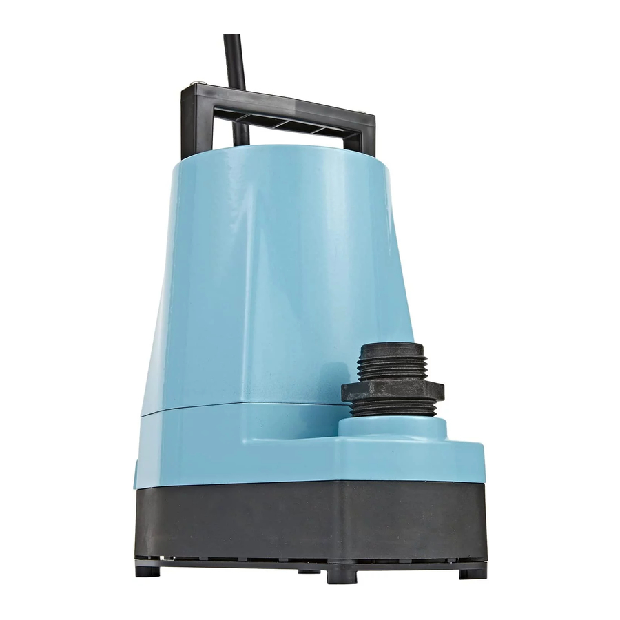
5-MSP SERIES USER MANUAL
Little Giant 5-MSP 115-Volt, 1/6 HP, 1200 GPH Aluminum Manual Utility Pump, 10-Ft. Cord, Blue, 505000
ELECTRICAL CONNECTIONS
- Check the pump label for proper voltage required. Do not connect to voltage other than that shown.
![]()
If pump is supplied with a 3-prong electrical plug, the third prong is to ground the pump to prevent possible electrical shock hazard. DO NOT REMOVE the third prong from the plug. A separate branch circuit is recommended. Do not use an extension cord. Do not cut plug from the cord. If the plug is cut or the cord is shortened, then this action will void the warranty.- If the power cord is equipped with stripped lead wires, such as on 230V models, be sure that the wires are connected to a power source correctly. The green/ yellow wire is the ground, and the blue (or white) and brown (or black) are live.
- If any failure occurs in the power cord, contact any authorized personnel or the manufacturer.
CONSULT INSTRUCTION SHEET ILLUSTRATIONS FOR PROPER ASSEMBLY AND DISASSEMBLY OF YOUR PUMP.
OPERATION
- Place pump on solid surface in water at least 3/4" deep to begin pumping. Pump should be totally submerged for proper cooling of the motor when pump is operated for extended periods.
- Connect garden hose to hose adaptor or 1" diameter pipe directly into pump outlet.
- Pump with screen will remove water to within 3/8". Pump without screen (it will snap off by wedging a coin between the slots; see Figure 2) will remove water to within 1/8".
- If the surface is dirt or sand, place pump on flat surface such as a piece of wood or metal to prevent it from being clogged.
- Do not let the unit run dry. It is designed to be cooled by pumping fluid. You may damage the seal and the motor may fail if the pump is allowed to run dry.
- If the unit is going to be idle for a period of time, follow the cleaning instructions outlined in the next section. Do not let the unit freeze in the wintertime. This may cause cracking or distortion that may destroy the unit.
- When using 3/4" garden hose adaptor performance will be reduced approximately 15%. This pump does not deliver enough pressure to operate lawn sprinklers properly.
- If fused-type plug is used on 230V units, a 5.0 amp fuse is recommended.
- If using an aluminum body pump in an area with water having a high mineral content (hard water) or if other metals (copper tubing, metal fountain heads, etc.) are present in the pond or fountain, a condition called "galvanic corrosion" may occur. The recommended solution to this situation is the use of a sacrificial anode attached to the pump. This anode works on the same principle as the anode found in hot water heaters and boat motors. Contact your local distributor and ask for the model SA-1 by Little Giant.
MAINTENANCE
DISCONNECT THE PUMP FROM THE POWER SOURCE BEFORE SERVICING OR REMOVING ANY COMPONENT!
- The motor housing of the pump is completely sealed and requires no service. Disassembly of the motor housing or alteration of the power cord voids all warranty. The power cord on these units cannot be replaced. In case of damage the whole unit must be replaced.
- The motor is a continuous duty type sealed in oil with an automatic thermal overload protector device.
- The pump can run against a restricted discharge such as a fountain without damage to the pump.
- If the pump becomes clogged snap the screen off and clean out the area.
- If necessary remove the 6 screws holding the volute base to the motor housing and clean the volute.
- If the impeller is removed, make sure that a spacing of.050" (1.27 mm) with shaft pushed toward housing is maintained when reassembling (Figure 1).
![]()
- When reassembling, remember to install the seal ring between the volute base and the motor housing.


| ITEM | PART NO. | DESCRIPTION | QTY. |
| 1 | 902441 | Screw | 2 |
| 2 | 105918 | Handle, black | 1 |
| 3 | 599030 | Adaptor, black | 1 |
| 4 | 105310 | Impeller | 1 |
| 5 | 928024 | Seal ring | 1 |
| 6 | 105375 | Volute, black | 1 |
| 7 | 902434 | Screw | 6 |
| 8 | 105376 | Screen, black | 1 |
| 9* | 941038 | Adaptor, tubing | 1 |
*Not on all models
SAFETY GUIDELINES
- Ensure that unit is disconnected from power source before attempting to service or remove any component.
- Do not use to pump flammable or explosive fluids such as gasoline, fuel oil, kerosene, etc. Do not use in explosive atmospheres. Pump should only be used with liquids compatible with pump component materials.
- Do not handle pump with wet hands or when standing on a wet or damp surface or in water.
![shock hazard]() This pump is supplied with a grounding conductor and/or grounding-type attachment plug. To reduce the risk of electric shock, be certain that it is connected to a properly grounded grounding-type receptacle.
This pump is supplied with a grounding conductor and/or grounding-type attachment plug. To reduce the risk of electric shock, be certain that it is connected to a properly grounded grounding-type receptacle.- In any installation where property damage and/or personal injury might result from an inoperative or leaking pump due to power outages, discharge line blockage, or any other reason, a backup system(s) and/or alarm should be used.
- Support pump and piping when assembling and when installed. Failure to do so may cause piping to break, pump to fall, motor bearing failures, etc.
- If pump is an oil-filled pump, the motor housing is filled with a dielectric lubricant at the factory for optimum motor heat transfer and lifetime lubrication of the bearings. Use of any other lubricant could cause damage and void the warranty. This lubricant is non-toxic; however, if it escapes the motor housing, it should be removed from the surface quickly by placing newspapers or other absorbent material on the water surface to soak it up, so aquatic life is undisturbed.
LIMITED WARRANTY
| For parts or repair, please contact | 1-888-572-9933 | |
| For technical assistance, please contact | 1-888-956-0000 | |
www.LittleGiantPump.com
CustomerService-WTS@fele.com
Franklin Electric Co., Inc.
P. O. Box 12010
Oklahoma City, OK 73157-2010
Phone: 405-947-2511 • Fax: 405-947-8720
www.LittleGiantPump.com
CustomerService-WTS@fele.com
Documents / Resources
References
Download manual
Here you can download full pdf version of manual, it may contain additional safety instructions, warranty information, FCC rules, etc.
Download Little Giant 5-MSP Series, 505000, 506160 - Pump Manual
Advertisement


Need help?
Do you have a question about the 5-MSP Series and is the answer not in the manual?
Questions and answers