
Related Manuals for Kingsman Fireplaces ZCV34 Series


Summary of Contents for Kingsman Fireplaces ZCV34 Series
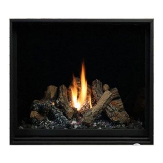
- Page 1 ZCV34, ZCV39 & ZCV42 Series Installation Instructions Pictured: ZCV34N FOR QUESTIONS AND CONCERNS, CONTACT US AT FOR QUESTIONS AND CONCERNS, CONTACT US AT www.allpartsinc.com Call Us: 1-269-685-4123 Text Us: 1-269-447-0412...
-
Page 2: Installation Instructions
Installation Instructions Model Numbers: ZCV39N, ZCV39NE, ZCV39NE2, ZCV39LP, ZCV39LPE, ZCV39LPE2 ZCV42N, ZCV42NE, ZCV42NE2, ZCV42LP, ZCV42LPE, ZCV42LPE2 Certified to: ANSI Z21.88-2017 • CSA 2.33-2017, CSA 2.17-2017 BENTLEY Vented Gas Fireplace Heaters Model Numbers: ZCV39NH, ZCV39NHE, ZCV39NHE2, ZCV39LPH, ZCV39LPHE, ZCV39LPHE2 ZCV42NH, ZCV42NHE, ZCV42NHE2, ZCV42LPH, ZCV42LPHE, ZCV42LPHE2 Certified to: ANSI Z21.88-2017 •... -
Page 3: Table Of Contents
Table of Contents INFORMATION Table of Contents……………………………………………………………..............Pre-installation Questions and Answers / Operations and Maintenance Instructions..........Warnings, Installations, and Operations…………………………………..............Installation Requirements for the Commonwealth of Massachusetts / Carbon Monoxide (CO) Detector....Fireplace Installations in Covered Outdoor Locations.................... Recommendations for Finishing of Clean View Installations.................. Mobile Home/Manufactured Housing Installation……………………............... - Page 4 Gas Line Installation………………………………………………………………………………………………………... Millivolt System, Lighting, and Burner Control…………………………………………………………………………... Annual Inspection List for Determining Safe Operation of a Direct Vent Gas Fireplace......... Burner System Maintenance………………………………………………………………………………………………. Conversion Kit Instructions – PART A……………………………………………………………………………………. 58-59 Gas Conversion Kit For Top Convertible Pilot PART B………………………………………………………………… Gas Conversion for Modulator –...
-
Page 5: Pre-Installation Questions And Answers / Operations And Maintenance Instructions
Pre-installation Questions and Answers About curing of the paint Your stove or fireplace has been painted with the highest quality silicone stove paint. This paint dries quickly in 15-20 minutes when first applied at the factory. However, due to the high temperature silicone components, the paint will cure when heat is applied to the appliance as it is first used. -
Page 6: Warnings, Installations, And Operations
Warnings, Installations and Operations - Installation Regulations This gas appliance must be installed by a qualified installer in accordance with local building codes, or in the absence of local codes, with the current CAN/CSA-B149.1 or .2 Installation Code (in Canada) or the current National Fuel Gas Code Z223.1- NFPA 54 when installed in the United States. -
Page 7: Installation Requirements For The Commonwealth Of Massachusetts / Carbon Monoxide (Co) Detector
Installation Requirements for the Commonwealth of Massachusetts In the Commonwealth of Massachusetts, the installer or service agent shall be a plumber or gas fitter licensed by the Commonwealth. When installed in the Commonwealth of Massachusetts or where applicable codes; the unit shall be installed with a CO detector per the requirements listed below. -
Page 8: Fireplace Installations In Covered Outdoor Locations
Fireplace Installations in Covered Outdoor Locations – FOR BASIC MILLIVOLT UNITS ONLY- NO FAN – NO LIGHTS- CAUTION – Installation of an indoor gas fireplace with an outdoor exposure is not covered under the (ANSI Z21.88 – CSA 2.22 or ANSI Z21.50 – CSA 2.33) standard(s) used to certify the indoor gas-fired fireplace. The Intertek safety certification will not apply to this installation method. -
Page 9: Recommendations For Finishing Of Clean View Installations
Recommendations for Finishing of Clean View Installations When finishing the wall around the fireplace, it is critical that the wall covering be fastened properly. It is acceptable to pre-drill holes and use self-tapping screws which may be used to fasten a backer for tile, marble, etc. Screws being installed through non-combustible board should be self-tapping type with a maximum length of 2 inches. -
Page 10: Mobile Home/Manufactured Housing Installation
Mobile Home/Manufactured Housing Installation This Direct Vent System Appliance must be installed in accordance with the manufacturer’s installation instructions and the Manufactured Home Construction and Safety Standard Title 24 CFR, Part 3280, or the current Standard for Fire Safety Criteria for Manufactured Home Installations, Sites, and Communities ANSI/NFPA 501A, and with CAN/CSA Z240 MH Mobile Home Standard in Canada. -
Page 11: Nailing Tab Guide
ZCV39 / ZCV42 Framing- Nailing Tab Guide [Qty]2 Nailing Tabs are located on each side of the front frame. These Nailing Tabs can be used in two ways: 1/2” Drywall Flush with Face of Fireplace – Framing Flush with Face of Fireplace -Fireplace to be covered Fireplace and Combustible Wall to be covered with Non-Combustibles (e.g. -
Page 12: Zcv39 / Zcv42 Framing Your Gas Fireplace
ZCV39 / ZCV42 Framing Your Gas Fireplace This section is intended for qualified installers only. Before beginning, make note of where the gas and electrical accesses are located on the unit. This will streamline the construction process. Furthermore, familiarize yourself with the venting and clearance requirements (see Venting section) for this appliance. -
Page 13: Left Side
ZCV39 Locating Your Appliance LOCATION KEY: Flat on Wall Across the Corner As an Island As a Room Divider Flat on Wall Corner Exterior Wall See Mantel Leg Clearances Instruction for the proper placement of fireplace. Island installation with a top vent is possible as long as the horizontal portion of the vent system does not exceed 20 feet (6.1 m). -
Page 14: Framing Dimensions
ZCV39 Framing Dimensions Determine whether face of fireplace will be: Flush with finished wall (e.g., for surround, cultured stone or other non combustible covering). Flush with framing (to be covered with concrete board for a Flat Wall appearance). Refer to Nailing Tab Guide section also. -
Page 15: Clearance To Combustibles
ZCV39 Clearance to Combustibles Clearance to Combustibles ZCV39 36” [92cm] Front 0” [0cm] Back (from Stand-offs) 0” [0cm] Side (from Stand-offs) 0” [0cm] Floor* 55-1/2” [141cm] Minimum Ceiling Height (from bottom of fireplace) 0” [0cm] Top (from Stand-offs) 4” [10.2cm] Top of 90°... -
Page 16: Facing Requirements
ZCV39 Facing Requirements Required Non-Combustible Areas FIREPLACE WITH SCREEN ONLY (AS SHIPPED) SHOWN HERE. Refer to BASIC FINISHING Sections 1-6 for important finishing details. Recommended: Non-Combustible 39-1/2” x 41” This is to allow concrete board to be screwed to framing if used. -
Page 17: Locating Your Appliance / Fireplace Dimensions
ZCV42 Locating Your Appliance LOCATION KEY: Flat on Wall Across the Corner As an Island As a Room Divider Flat on Wall Corner Exterior Wall See Mantel Leg Clearances Instruction for the proper placement of fireplace. Island installation with a top vent is possible as long as the horizontal portion of the vent system does not exceed 20 feet (6.1 m). -
Page 18: Framing Dimensions
ZCV42 Framing Dimensions Determine whether face of fireplace will be: Flush with finished wall (e.g., for surround, cultured stone or other non combustible covering). Flush with framing (to be covered with concrete board for a Flat Wall appearance). Refer to Nailing Tab Guide section also. -
Page 19: Clearance To Combustibles
ZCV42 Clearance to Combustibles Clearance to Combustibles ZCV42 36” [92cm] Front 0” [0cm] Back (from Stand-offs) 0” [0cm] Side (from Stand-offs) 0” [0cm] Floor* 59.5” [151cm] Minimum Ceiling Height (from bottom of fireplace) 0” [0cm] Top (from Stand-offs) 3-1/2” [8.9] Top of 90°... -
Page 20: Facing Requirements
ZCV42 Facing Requirements Required Non-Combustible Areas FIREPLACE WITH SCREEN ONLY (AS SHIPPED) SHOWN HERE. Refer to BASIC FINISHING Sections 1-6 for important finishing details. Recommended: Non-Combustible 42-5/8” x 44” This is to allow concrete board to be screwed to framing if used. -
Page 21: Basic Finishing 1: With Screen Only
ZCV39 / ZCV42 Basic Finishing 1: With Screen Only Step One: Frame Fireplace with nailing tabs oriented as Step Two: Use Drywall to finish face of wall. shown. NOTE: Drywall will be flush with fireplace face. Drywall Fireplace Frame Nailing Tab Step 3: A brick, tile, or other non-combustible border IMPORTANT NOTE!: If installing tile, brick, or other non-... -
Page 22: Zcv39Css / Zcv42Css Child Safety Screen Installation
ZCV39CSS / ZCV42CSS Child Safety Screen Installation Contents of Kit: [1] Child Safety Screen- Ready to Install Assembly Instructions: Attach screen to fireplace as per instructions below. ⚠ WARNING: Wait until unit is COMPLETELY cool before touching glass or attempting to install or remove Child Safety Screen. -
Page 23: Zcv39Css2 / Zcv42Css2 / Zcv48Css2 Inside Fit Safety Screens
ZCV39CSS2 / ZCV42CSS2 / ZCV48CSS2 Inside Fit Safety Screens Contents of Kit: [1] Child Safety Screen- Ready to Install Assembly Instructions: Attach screen to fireplace as per instructions below. ⚠ WARNING: Wait until unit is COMPLETELY cool before touching glass or attempting to install or remove To install screens hook bottom clip onto glass Child Safety Screen. -
Page 24: Basic Finishing 2: With S1 Or S1Pf Surround
ZCV39 / ZCV42 Basic Finishing 2: With S1 or S1PF Surround Step One: Frame Fireplace with nailing tabs oriented as Step Two: Use Drywall to finish face of wall. shown. NOTE: Drywall will be flush with fireplace face. Drywall Fireplace Frame Nailing Tab Step 3: Once wall is completely finished, Screen with Surround IMPORTANT NOTE!:... - Page 25 S1PF Surround Required Clearance ZCV39 Fireplace Opening Bottom of Unit S1 Surround Required Clearance ZCV42 Fireplace Opening Bottom of Unit S1PF Surround Required ZCV42 Clearance Fireplace Opening Bottom of Unit...
-
Page 26: Basic Finishing 3: Concrete Board Behind S2Pf Surround (3/4" Maximum Total Thickness)
ZCV39 / ZCV42 Basic Finishing 3: Concrete Board Behind S2PF Surround (3/4” Maximum Total Thickness) Step One: Step Two: Use Concrete Board to cover fireplace face. Frame Fireplace with nailing tabs oriented as shown (flush with face of fireplace). NOTE: Optional ZCV-TLK Tile Kit is available. Maintain clearances shown. -
Page 27: Basic Finishing 4: Stone Or Brick Around S2Pf Surround
ZCV39 / ZCV42 Basic Finishing 4: Stone or Brick Around S2PF Surround Step One: Step Two: Use Drywall to finish face of wall. Frame Fireplace with nailing tabs oriented as shown. NOTE: Drywall will be flush with fireplace face. Drywall Fireplace Frame Nailing Tab Step 3: A stone, brick, or other non-combustible border... -
Page 28: Basic Finishing 5: Tile Border Behind S2Pf Surround (3/4" Maximum Total Thickness)
ZCV39 / ZCV42 Basic Finishing 5: Tile Border Behind S2PF Surround (3/4” Maximum Total Thickness) Step One: Step Two: Use Drywall to finish face of wall. Frame Fireplace with nailing tabs oriented as shown. NOTE: Drywall will be flush with fireplace face. Drywall Fireplace Frame Nailing Tab... -
Page 29: Zcv39 / Zcv42 Surround Installations
ZCV39 / ZCV42 Surround Installations Each Kit contains surround and [8] DT screws. NOTE: ZCV39CSS or ZCV42CSS Safety Screen is required to use these surrounds. All surrounds are mounted onto Screen as described below. Screen and surround are then mounted on unit as described in Child Safety Screen Installation section. -
Page 30: Basic Finishing 6: With Mqzcv42Dd & Stone, Brick, Or Tile Border
ZCV39 / ZCV42 Basic Finishing 6: With MQZCV42DD & Stone, Brick, or Tile Border Step One: Frame Fireplace with nailing tabs oriented as Step Two: Use Drywall to finish face of wall. shown. NOTE: Wall will be flush with fireplace face. Drywall Fireplace Frame Nailing Tab... - Page 31 1/2” Clearance is Required for Door to Open All DD Doors are flush with bottom of appliance. ⚠ NOTE FINISHED AREA IN FRONT OF FIREPLACE (FLOOR, HEARTH, ETC.) 1/2” Clearance MUST BE FLUSH WITH BOTTOM is required for OF FIREPLACE WHEN USING Door to Open DESIGNER DOORS.
-
Page 32: Mqzcv39Dd / Mqzcv42Dd Designer Door Installations
MQZCV39DD / MQZCV42DD Designer Door Installations Each Kit contains: Back Frame, Front Frame, and Screen. If protruding facing materials (i.e., concrete board, brick or tile) are to be used, refer to Facing Material Dimension Requirements section. Designer Doors require a minimum 1/8” space on top and sides to allow for installation & removal. ... -
Page 33: Zcv-Tlk Optional Tile Lip Kit
ZCV-TLK Tile Lip Kit Contents of Kit: Qty. [4] Tile Lip pieces 45-1/16” long, Qty. [12] screws. Instructions: Refer to the charts below to find your installation choice. -Cut [2] tile lip pieces to height of sides, and [2] to length of top &... -
Page 34: 39Zcv Mantel Clearances
39ZCV Mantel Clearances Before installing any mantels it is important to determine the combustibility of its material(s). There are two types of mantels to consider: Combustible and Non-Combustible. A Combustible Mantel is one that consists of material(s) that may discolor, combust, or lose its integrity in the presence of heat. -
Page 35: 42Zcv Mantel Clearances
42ZCV Mantel Clearances Before installing any mantels it is important to determine the combustibility of its material(s). There are two types of mantels to consider: Combustible and Non-Combustible. A Combustible Mantel is one that consists of material(s) that may discolor, combust, or lose its integrity in the presence of heat. -
Page 36: Zcv39 / Zcv42 51Uhs Box / Component Locations
ZCV39 / ZCV42 51UHS Box Included with base model. The 51-UHS is designed for millivolt and IPI units for in-unit installation of the Remote Receiver, Fan Control Module, and the IPI Module. 51-UHS can be inserted & removed from beneath fireplace through access panel opening (Remove glass door first). NOTE: When using a remote control, the 51-UHS must be used. -
Page 37: Zcv39 / Zcv42 Z46Fk Fan Kit Installation
ZCV39 / ZCV42 Z46FK Fan Kit Installation ⚠ WARNING The fan can be installed through the side of the fireplace. Electrical Grounding Instructions This appliance is equipped with a three prong (grounding) plug for your protection against If fireplace is already installed, the shock hazard and should be plugged directly into a properly grounded three-prong burner pan must be removed to receptacle. -
Page 38: Fan Speed Control Outside Of Fireplace
Split Receptacle- Fan Speed Control Outside of Fireplace If you plan to locate the variable speed control switch for the fan outside of the fireplace and you require a constant source of AC power inside the unit for another accessory such as lights or an IPI valve system, follow one of the procedures below. -
Page 39: Zcv39Pl / Zcv42Pl Porcelain Liner Installation
ZCV39PL / ZCV42PL Liner Installation ⚠ WARNING: Failure to position the parts in accordance with these diagrams or failure to use only parts specifically approved with this appliance may result in property damage or personal injury. ZCV39PL / ZCV42PL Consists of: [1] –... -
Page 40: Zcv39Rl / Zcv42Rl Brick Liner Installation
ZCV39 RLT / RLH / RRH / RLS & ZCV 42RLT / RLH / RRH / RLS Brick Liner Installation NOTE: To use with GT Glass Tray, refer to Cutting Refractory Liners page in manual. Step One: Remove Log Holder. Step Two: Place Back Liner against back wall of firebox. -
Page 41: Cutting Refractory Liners To Work With Gt Glass Trays
ZCV39 / ZCV42 -Cutting Refractory Liners to work with GT Glass Trays- Refractory Liners must be cut if they are to be used with a Glass Tray. Caution: Liners are extremely fragile. Handle with care. 1. Using a utility knife, measure and cut Back Liner, removing the two side portions at the bottom. -
Page 42: Zcv39Gt/ Zcv42Gt Glass Tray Setup
ZCV39GT/ ZCV42GT Glass Tray Setup Parts List: [1] Glass Tray,[1] Pilot Shield, [1] Glass Retainer, [3] DT Screws. NOTE: To use with Refractory Liners, refer to Cutting Refractory Liners page in manual. Installation: Remove Log Holder and Log Grate. Place Glass Tray over Burner. Insert Pilot Cover into slots in Glass Tray. Glass Tray sits behind Door Latch Screws. -
Page 43: Ulk2 Universal Light Kit
ULK2 Universal Light Kit ( Optional Accent Lighting Kit) Please follow the current ANSI/NFPA 70 National Electrical Code in the USA and CAN/CSA C22.1 Canadian National Electrical Code in Canada. Contents of Kit: [2] 12V Halogen Lamps Lamp Plate with Insulated Studs & wiring ... - Page 44 Screw Screw ZCV39 / ZCV42 STEP 3: Place Lamps in position in firebox. Attach to fireplace with a single screw at the locations shown above for each unit. Lamps can be placed facing upward or sideways. Replace burner and false bottom if used, along with pilot shield.
-
Page 45: Log F3 Setup
ZCV39 / ZCV42 Log F3 NOTE: Set Primary Air Opening at 1/8” for Natural Gas. Refer to Gas Conversion and Burner Removal sections in manual. Pull Up [4] Log Tabs *These items are supplied with the fireplace. *Insulation Wool *Lava Rock Pull up [4] Log Tabs on Burner. -
Page 46: Mq42D Setup
ZCV39 / ZCV42 MQ42D NOTE: ZCV39GT OR ZCV42GT REQUIRED. *NOTE: THESE ITEMS ARE SUPPLIED WITH THE FIREPLACE: LOG 1 *Lava Rock LOG 4 *Embers LOG 5 LOG 2 *Vermiculite LOG 3 LOG 6 *Insulation Wool STEP 1: Place LOG 1, LOG 2, and LOG 3 as shown. - Page 47 LOG 6 Place Log 6 as shown above. Setup is complete. ⚠ WARNING: Failure to position the parts in accordance with these diagrams or failure to use only parts specifically approved with this appliance may result in property damage or personal injury...
-
Page 48: Rbcb1 Cannonballs
RBCB1 -Cannonballs- Installation Instructions *Must be used with ZCV39GT/ ZCV42GT Glass Tray Assorted size and colors. Place randomly as desired inside fireplace. Can be used with MQ Glass, MQ Ember, and / or Lava Rock. Do not place Cannonballs directly on burner ports. If sooting occurs change position of or remove affected objects. -
Page 49: Mq Dealer Accessories For Zcv39 / Zcv42
MQ Dealer Accessories for ZCV39 / ZCV42 The following Accessories are available through MQ Dealers only. GLASS (MQG5W, MQG5C, MQG5A, MQG5B, MQG5ZG) ACCESSORY ITEM DESCRIPTION If you wish to use this media evenly spread the glass embers onto the false bottom and burner. - Page 50 MQ39D Driftwood Log Set- 4pcs - Must be used with ZCV39GT/ ZCV42GT Glass Tray NOTE Pilot Area Must Not Be Covered, as delayed ignition can occur. Insulation Wool & MQ EMBER (shown, supplied with Base Unit), or MQ Glass can be placed on Burner.
-
Page 51: Mq Stone Decorative Stone Set
MQ STONE DECORATIVE STONE SET- Must be used with ZCV39GT/ ZCV42GT Glass Tray MQ Stone can be placed on or around Burner. Lava Rock (Supplied with Base MQ EMBER (shown) can be placed on Burner. Unit). Do not place on Burner. MQ Glass can be placed on Burner and Glass Tray. -
Page 52: Mq Log F9 Setup
MQ Log F9 Setup NOTE: Set Primary Air Opening at 3/16” for Natural Gas. Refer to Gas Conversion and Burner Removal sections in manual. Pull Up [4] Log Tabs *Embers *Lava Rock Pull up [4] Log Tabs on Burner. *Insulation Wool Match with Holes in Logs 4 &... - Page 53 ⚠ WARNING: Failure to position the parts in accordance with these diagrams or failure to use only parts specifically approved with this appliance may result in property damage or personal injury. Logs 8-10 are placed along Front Grate. Embers & Insulation Wool On Burner Lava Rock &...
-
Page 54: General Installation, Use, And Maintenance Zcv39 & Zcv42 Door Installation
ZCV39 / ZCV42 / MCVST42 / MCVP42 Door Installation To install Door: 1. Remove Access Cover below Glass Door. 30° 15° 2. Engage door in lower latches at an angle of between 15 and 30 degrees. 3. Swing door up and pull top latches over door lip at each corner. Door Bottom Latch ⚠... -
Page 55: Door And Glass Information
Door and Glass Information Glass Cleaning It will be necessary to clean the glass periodically. During startup, condensation, which is normal, forms on the inside of the glass, and causes dust, lint etc. to cling to the glass surface. Also, initial paint curing can deposit a slight film on the glass. It is therefore recommended that initially the glass be cleaned two or three times with a fireplace glass cleaner. -
Page 56: Gas Line Installation
Gas Line Installation This gas appliance should be installed by a qualified installer in accordance with local building codes and with current CAN/CGA - B149.1 or .2 installation codes for Gas Burning appliances and equipment in Canada and the National Fuel Gas Code ANSI Z223 in the U.S.A. -
Page 57: Millivolt System, Lighting, And Burner Control
Millivolt System, Lighting, and Burner Control FOR YOUR SAFETY READ BEFORE LIGHTING WARNING: If you do not follow these instructions exactly, a fire or explosion may result causing property damage, personal injury or loss of life. BEFORE LIGHTING This appliance has a pilot which must be lighted by hand. When ... -
Page 58: Annual Inspection List For Determining Safe Operation Of A Direct Vent Gas Fireplace
Annual Inspection List for Determining Safe Operation of a Direct Vent Gas Fireplace Refer to this checklist for proper maintenance, safe use, and operation. See each section for more specific information. 1. Inspect and operate all pressure relief mechanisms (i.e., relief dampers, spring loaded door latches) installed on your appliance to verify relief mechanisms are free from obstruction to operate. -
Page 59: Burner System Maintenance
Burner System Maintenance It is recommended to annually inspect and clean the Burner System to prevent malfunction and / or sooting. This operation should be performed by your dealer or a qualified technician. -CAUTION- Before servicing the burner system ensure that the gas supply is turned OFF and disconnect all electrical connections to the appliance. - Page 60 Gas Conversion Part A ZCV39 / ZCV42 IMPORTANT: Always check for gas leaks with a soap and water solution. DO NOT USE OPEN FLAME FOR LEAK TESTING. Main Burner Air Shutter & Screw Pilot Orifice Main Burner Orifice Brass Nipple Parts List: ...
-
Page 61: Gas Conversion Kit For Top Convertible Pilot Part B
Gas Conversion for Top Convertible Pilot – Part B (series 0190XYZ) Instructions for converting SIT 190 series pilot burner injector from NG to PROPANE and from PROPANE to NG only. This information should be considered as supplemental to the Appliance Manufacturer's Instructions. -
Page 62: Gas Conversion For Modulator - Part C
Gas Conversion for Modulator – PART C... -
Page 63: Burner Removal / Burner System Removal / Installation
ZCV39 / ZCV42 Burner Removal To remove grate, remove two [2] screws from grate bar assembly. To remove burner, remove four [4] screws from burner. Slide burner to the left and lift to remove. -⚠ WARNING- Turn off Unit and allow to cool before cleaning. -
Page 64: Ipi Electronic Ignition System
IPI Electronic Ignition System Overview Cover The IPI system is an advanced burner controller that provides you with the option of having either a Standing- Pilot, or an intermittent igniting system. This alternating Backup mode is controlled by the CPI/IPI Switch (Continuous Pilot Battery Ignition/Intermittent Pilot Ignition) located on the IPI System Pack... -
Page 65: Remote Control Operation
Proflame 1 -Remote Control Operation- The Proflame GTM is configured to control the on/off main burner operation, its flame levels, and provides on/off and Smart *thermostatic control of the appliance. Transmitter Remote Receiver Transmitter Room *thermostat ( Transmitter Operation) The Transmitter is powered by 3 AAA type batteries. A Mode The Remote Control can operate as a room *thermostat. -
Page 66: Ipi Electronic Ignition Parts List - Standard System
IPI Electronic Ignition Parts List – Standard System ITEM NO. PART NO. DESCRIPTION 1006-P002si Valve IPI Hi/Lo NG 1006-P003si Valve IPI Hi/Lo LP *1002-P047si Pilot Assembly-LP -24” Wire *1002-P033si Pilot Assembly-NG -24” Wire 1002-P017si Spark Electrode (with wire) *1002-P119si Spark Electrode (with wire- 35” Length) 1002-P903si Electrode Flame Sensor *1002-P910si... -
Page 67: Configuration 1: Basic Manual Hi / Lo And Manual Off
Configuration #1: Basic manual HI/LO and manual ON/OFF capabilities. -
Page 68: Configuration 2: Remote On / Off And Manual Hi / Lo
Receiver Module .584.523/521/221 1001-P221SI Receiver Module .584.523/521/221 1001-P221SI... -
Page 69: Operating The Receiver Without Batteries For Gt / Egt / Gtm / Egtm Remote Controls
Operating the Receiver Without Batteries For GT / EGT / GTM / EGTM Remote Controls -Wiring Harness P/N 1002-P906si required for both IPI & Millivolt systems. -Millivolt Systems will also require Power Adapter P/N 1002-P850si. The Remote Receiver & IPI or Millivolt system can be powered by the AC Adapter. This is advantageous if you do not want to use batteries. -
Page 70: Configuration 3: Remote On/Off, Variable Hi/Lo, And Fan
Configuration #3: Remote ON/OFF, variable HI/LO, and fan capabilities. Refer to the fan installation/removal section for fan installation. -
Page 71: For Your Safety Read Before Lighting
- Lighting Instructions - Intermittent Pilot Ignition System (IPI) FOR YOUR SAFETY READ BEFORE LIGHTING WARNING: If you do not follow these instructions exactly, a fire or explosion may result causing property damage, personal injury or loss of life. Always light the pilot whether for the first time or if the gas supply has run out with the glass door opened or removed. -
Page 72: Proflame 2- Parts List- Basic System, Parts List, Configuration Gtmfl
Proflame 2 –NE2 / LPE2 -IPI System Parts List- IPI PROFLAME 2 - COMPONENT PARTS IPI - PF1 and PF2 Common Components PART NO. DESCRIPTION PART NO. DESCRIPTION 1005-P001SI Valve IPI Proflame PF2 885.001 NG - Stepper 12. 1002-P033SI TC - Pilot Burner IPI (Assembled) NG 199.033 1005-P002SI Valve IPI Proflame PF2 885.002 LP - Stepper 13. -
Page 73: Proflame 2 Remote Control
Proflame 2 Remote Control LCD Display ON / OFF Key Thermostat Key Batteries UP / DOWN Arrow Key Mode Key Button Within 10 seconds press the button again until Pairing Remote Control: you hear it beep. Install the 3 AAA type batteries in the battery bay, ... -
Page 74: Cold Climates - Cpi Setting - Proflame 2 Remote Control
Cold Climates – CPI Setting - Proflame 2 Remote Control Use the CPI setting during cold weather, otherwise the fireplace may have a hard time starting up and establishing a flame. The CPI (Continuous Pilot Ignition) setting will keep the firebox and fireplace exhaust vent warm during cold weather. When the firebox and exhaust vent are warm, exhaust gasses will readily flow out of the firebox. -
Page 75: Proflame 2 Remote Control
Proflame 2 Remote Control... - Page 76 Note: When Smart Thermostat is activated, manual flame height adjustment is disabled. Note: This function is only available in Room Thermostat or Smart Thermostat Control Mode.
-
Page 78: Vent Terminal Clearances
Vent Terminal Clearances Clearances are to the edge of the terminal plate. Add 6-3/4” to clearances to arrive at centerline. Local codes or regulations may require different clearances. WARNING: A HORIZONTAL VENT CERTIFIED GUARD (SAFETY CAGE) IS AVAILABLE WHEN REQUIRED BY LOCAL CODES. Canadian installations US installations Clearance above grade, veranda,... -
Page 79: General Vent Installation
General Vent Installation Information This gas appliance is approved to be vented either through the side wall or vertically through the roof. Only Kingsman Flex (Z-Flex) Venting Kits and components specifically approved and LABELED for this stove may be used. This appliance is also approved for use with M & G-Duravent Direct Vent system (Duravent Pro), BDM Pro Form Direct Vent, Ameri-Vent Direct Vent Pipe System, ICC Excel Direct, Metal Fab Sure-Seal DV and Selkirk Direct Temp. -
Page 80: Venting Routes And Components
Venting Routes And Components Venting Routes and Components Since it is very important that the vent system maintain its How to Use the Horizontal Vent Table balance between the combustion air intake and the flue gas 1. Determine the height of the system and the number of exhaust, certain limitations as to vent configurations apply and bends required. -
Page 81: Z47St24 / Z47St36 Horizontal Snorkel Terminations
Z47ST24 / Z47ST36 Horizontal Snorkel Terminations Two snorkel terminations are available if a vertical rise is necessary on the exterior side of a building: Z47ST24 (24” Tall, 14-1/2” Center to Center) Z47ST36 (36” Tall, 26-1/2” Center to Center) Follow standard horizontal venting installation procedures. If the Snorkel Termination is to be located below grade, a window well is recommended with adequate and proper drainage as per local codes. -
Page 82: Venting Straight Up Through Roof
Venting Straight Up Through Roof An Attic Insulation Shield must be installed where the vent passes from a lower living space into an attic space where the chimney is not enclosed. It is designed to keep insulation materials away from the chimney. When installing the Attic Insulation Shield where the chimney passes from a living space to an attic space, install the shield from below and nail in place using 1"... - Page 83 -Restrictor- Remove for Runs Under 15 Feet Clearances in horizontal venting. FDVVT40 Clearance to perpendicular wall 24 inches (60 cm). (Recommended to prevent re- circulation of exhaust products. For additional requirements check local codes.) 24” 18” MIN Clearance above highest point of exit on roof 18 inches (45cm) 43ft...
-
Page 84: Installations Using Co Linear Flex Kits
Fireplace Installations Using Co Linear Flex Kits CAUTION – The following installation procedure is not covered under the appliance safety standard (ANSI Z21.88 – CSA 2.22 or ANSI Z21.50 – CSA 2.33) used in the safety certification of this appliance. The Intertek safety certification does not apply to this installation. -
Page 85: Approved For Power Vent Pvh58
Approved for Power Vent PVH58 / PVH58FM - This appliance is approved for use with a Kingsman PVH58 Horizontal Power Vent - A Horizontal Power Vent Termination is intended for use where standard venting configurations are not possible. NOTE: MODELS EQUIPPPED WITH MILLIVOLT/ STANDING PILOT IGNITION: Downward vertical vent runs are NOT permitted. -
Page 86: Power Vent Control Module Installation
Bentley ZCV39 / ZCV42 Power Vent Control Module Installation FIREPLACE IS SUPPLIED WITH ONE JUNCTION BOX. ADDITIONAL OUTLETS MAY BE REQUIRED. CONSULT A QUALIFIED ELECTRICIAN. MAIN WIRING HARNESS IPI SYSTEM POWER VENT CONTROL MODULE DOUBLE POLE SWITCH MV SYSTEMS ONLY MAIN WIRING HARNESS NOTE: Fireplace glass door must be removed to... -
Page 87: Power Vent Parts List - 4/7 Venting
Power Vent Parts List – 4/7 Venting NUMBER DESCRIPTION PVH58 Horizontal Power Vent Starter Kit ‐ Exterior Mount PVH58FM Horizontal Power Vent Kit ‐ Flush Mount Note: Must use a one foot section of 5/8 DV hard pipe to connect to the Power Vent Termination (not supplied) CHOOSE CONTROL MODULE OR HARNESS DEPENDENT ON VALVE SYSTEM PVC58MV Power Vent Control Module ‐... -
Page 88: Zcv39 Parts List
ZCV39 Parts List MQSTONE Decorative Stones Fireplace Part Numbers MQROCK2 Rock Set Natural ZCV39N (Millivolt) Fireplace Heater rated, NG, MQROCK3 Rock Set Multi-Color Tempered Glass, Safety Screen MQEMBER Glowing Embers ZCV39NH (Millivolt) Fireplace Heater rated, NG, MQG5W Decorative Glass 1/2” White 5LB Ceramic Glass, Safety Screen MQG5A Decorative Ember Glass Cobalt Blue 5LB... - Page 89 39ZCV-BCKLP LP Ceramic Glass / upgrade Kit for 2000-080 Thermodisc 2450 (For Blower) ZCV39LP / LPE to ZCV39LPH /LPHE 1000-306 Thermalcord - Adhesive Back for Door Accessories Frame 1000-085 Z1MT Thermostat Millivolt Wall Mount Control Variable Speed KBWC-13BV FP15GC Stainless Steel Gas Connector Z80PT Thermostat Programmable Digital Millivolt Wall Mount (1F80-40)
-
Page 90: Zcv42 Parts List
ZCV42 Parts List MQEMBER Glowing Embers Fireplace Part Numbers MQG5W Decorative Glass 1/2” White 5LB ZCV42N (Millivolt) Fireplace Heater rated, NG, MQG5A Decorative Ember Glass Cobalt Blue 5LB Tempered Glass, Safety Screen MQG5B Decorative Ember Glass – Black 5LB ZCV42NH (Millivolt) Fireplace Heater rated, NG, MQG5ZG Decorative Glass- Zircon Glacier Ice 5LB... - Page 91 Z80PT Thermostat Programmable Digital Millivolt Wall Mount (1F80-40) Kingsman Fireplace Venting Valve System Parts / Millivolt Horizontal Vent Starter Kit - 3 FT Length ZDVHSK 1000-P136WR Generator / Thermopile Horizontal Vent Termination, Wall Thimble, 1001-P069SI Electrode Sparker 915.069 TC SIT 36”...
-
Page 92: Troubleshooting The Gas Control System
Troubleshooting the Gas Control System ⚠ WARNING BEFORE DOING ANY GAS CONTROL SERVICE WORK, REMOVE THE GLASS FRONT. NOTE: Before troubleshooting the gas control system, be sure external gas shut off is in the "On" position. Problem Possible Causes Corrective Action Spark igniter will not Defective or misaligned Check for spark at electrode and pilot: if no spark and electrode wire is... -
Page 93: Glass Safety- All Units
-Glass Safety- All Units IT IS THE RESPONSIBILITY OF THE HOME OWNER TO ENSURE THAT NO ONE TOUCHES A HOT APPLIANCE. If the barrier becomes damaged, the barrier shall be replaced with the manufacturer’s barrier for this appliance. Any safety screen, guard, or barrier removed for servicing the appliance, must be replaced prior to operating the appliance. -
Page 94: Limited Lifetime Warranty
This Limited Lifetime Warranty applies only while the unit remains at the site of the original installation and only if the unit is installed inside the continental United States, Alaska, Hawaii, and Canada. The warranty applies only if the unit is installed and operated in accordance with the printed instructions and in compliance with applicable installation and building codes and good trade practices.
Need help?
Do you have a question about the ZCV34 Series and is the answer not in the manual?
Questions and answers