Bosch ACS 651 Original Instructions Manual
A/c service unit
Hide thumbs
Also See for ACS 651:
- Repair instructions (40 pages) ,
- Original instructions manual (762 pages)
Table of Contents
Advertisement
Quick Links
Advertisement
Table of Contents

Related Manuals for Bosch ACS 651


Summary of Contents for Bosch ACS 651
- Page 1 ACS 651 en Original instructions A/C service unit...
-
Page 3: Table Of Contents
3.4.8 Oil / UV dye bottles Performing service in manual mode 3.4.9 Quick release couplers Flushing the ACS 651 after changing the 3.4.10 Inline filters oil type 3.4.11 Brakes Flushing the vehicle A/C system 3.4.12 Power cable and master switch 6.10 Refrigerant top-up... - Page 4 4 | ACS 651 | Maintenance Spare and wearing parts Refilling the refrigerant cylinder Service record 7.3.1 Last 3 system service reports 7.3.2 Last self test report 7.3.3 R134a Log 7.3.4 Transferring the R134a record to a USB disk 7.3.5...
-
Page 5: Symbols Used
Multi-step Instruction consisting of several steps. Copyright operation Software and data are the property of Bosch Limited or One-step Instruction consisting of one step. its suppliers and protected against copying by copyright operation laws, international agreements and other national legal... -
Page 6: Obligation Of Contractor
Before turning off the ACS 651, ensure that all the ser- Furthermore, the contractor must ensure that all elec- vice phases are complete. This prevents refrigerant from trical equipment and operating material is operated in escaping into the environment. -
Page 7: Safety Devices
A/C system. ACS 651 can perform are: The ACS 651 must always be monitored during opera- Recovery and recharge of the refrigerant tion. Do not leave the ACS 651 unattended when it is Vacuuming switched on. Oil injection Vehicle A/C service, using the ACS 651, must be prepa-... -
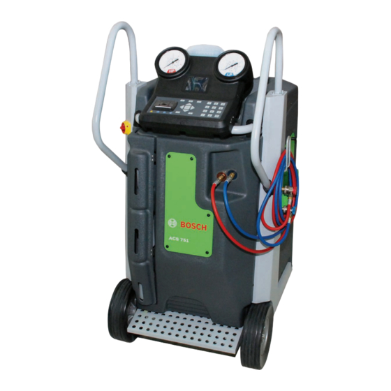
Page 8: Description Of Unit
8 | ACS 651 | Product description Description of unit Abb. 2: Rear view 1. HMI support 2 Master switch 3 Service hatch Abb. 1: Front view 4 Left panel 1 Handle 5 Rear panel 2 Human Machine Interface (HMI) -
Page 9: Description Of Function
The HMI module can be lifted and locked in position The ACS 651 is a fully automatic, compact, portable using the HMI support (Fig. 5, Pos. 1) on the rear of the A/C service unit. The ACS 651 can be operated manually HMI module. or automatically. -
Page 10: Selection And Function Keys
Navigate right or left See chapter 5 for troubleshooting. Return Clear Bosch supplies USB disks to update the ACS 651 soft- Switch between numeric and ware. If required, the USB disk can be plugged to the USB alphabetical entry port (Fig. 6, Pos. 1) to perform the firmware/software/ database update. -
Page 11: Service Hatches
Product description | ACS 651 | 11 3.4.6 Service hatches The service hatches on the right and left panels provide To provide easy access to components inside the access to the vacuum pump and the filter drier respec- ACS 651 during routine maintenance, service hatches tively. -
Page 12: Oil / Uv Dye Bottles
12 | ACS 651 | Product description 3.4.8 Oil / UV dye bottles Observe the symbols on the service hatch to identify To detach the UV contrast medium or fresh oil bottle, the bottles. The following table lists the symbols and pull the connector (Fig. -
Page 13: Inline Filters
(Fig. 2, Pos. 9) on the rear panel (Fig. 2, Pos. 5). The ACS 651 can be powered on by turning the switch to the vertical position. Abb. 13: Master switch Abb. -
Page 14: Before Turning On For The First Time
14 | ACS 651 | Commissioning Before turning on for the first time 4. Insert the end of the handle without the flange into 1. Remove the packaging of the handle. the grommet. 2. Fix one handle at a time. - Page 15 Commissioning | ACS 651 | 15 7. Push the edge protector to cover the area around Observe the red / blue identification stickers the flange. on the front panel before connecting the hoses. 8. Similarly, fix the other handle to the chassis.
- Page 16 16 | ACS 651 | Commissioning 14. Open the front service hatch (Fig. 1, Pos. 9). 17. Attach the oil and UV dye bottles to the respective connectors. Refer to chapter 3.4.8 for information on attaching the oil/UV dye bottles.
-
Page 17: Acs 651 Switch-On
(e.g. for Germany "German"). ACS 651 switch-on 9. Press E to confirm the language selected. 1. Move the ACS 651 to a flat, vibration-free surface. The following screen is displayed. 2. Apply the brake to prevent the unit from rolling away. -
Page 18: General Settings
R134a scale. 1. Connect the power cable to the mains supply. 2. Turn on the master switch on the ACS 651. 3. In the menu "ACS Settings" select the menu item "Calibration" and press E. -
Page 19: Refrigerant Tank Scale Calibration Check
Calibration Check NOK displayed, the refrigerant tank sensor has to be Before performing the calibration check, ensure that calibrated. Contact customer service to perform the ACS 651 is positioned on a horizontal, vibration- calibration. free surface. Operator list 1. In the main menu select "ACS Maintenance". -
Page 20: Changing The System Defaults
A/C system. Bosch will not accept any liability for damage either to the ACS 651 or the vehicle A/C system arising due to cross contamination. 3. Based on the type of oil (PAG or POE), select the quantity calculation type for oil recharge - absolute or delta. -
Page 21: R134A Recording Limit
Configuring the custom database 4.8.4 R134a recording limit The ACS 651 contains a database, to which a maximum Following successful transfer of the data to the of twenty vehicles can be added. The vehicle code, ve- USB stick, the R134a data records on the ACS 651 hicle model, year of make and the R134a are deleted automatically. -
Page 22: Filling The Internal Refrigerant Cylinder
The optimum placed in an inverted position during the filling process. refrigerant quantity for the ACS 651 is 5 kg - 9 kg. If the quantity is too less, you may not be able to rechar- If external cylinders with dip tube are used, the cylin- ge the refrigerant during service. -
Page 23: Viewing System Information
Commissioning | ACS 651 | 23 4.11 Viewing system information 8. Enter the quantity of R134a to be filled and press ¶ Press the i key. " The filling of the internal refrigerant cylinder starts. The system information is displayed. -
Page 24: R134A Record Transfer Tool
24 | ACS 651 | Commissioning 4.13 R134a record transfer tool 4.13.1 Installation The R134a record transfer tool has to be installed on your PC or laptop. This tool enables the transfer of R134a record from the USB disk to a PC / laptop. The R134a tool is made available on a CD supplied along with the operating instructions. -
Page 25: Troubleshooting
R Check if the used oil bottle is disconnected. If the bottle is disconnected, con- 4006 UV DYE RECHARGE Used Oil Bottle Not Found nect the bottle. R Check for blockage in the ACS 651. 5001 R134a RECHARGE Service Timeout R Check if quick couplers are open. - Page 26 Out of paper ter paper, use the order number F 002 DG1 450. A101 INTERNAL BOTTLE FILL Check for blockage in the ACS 651 Service Timeout A103 INTERNAL BOTTLE FILL R Weight limit reached. Reduce quantity of refrigerant in internal refrigerant cylin- Refrigerant Cylinder Full der.
- Page 27 A/C PERFORMANCE TEST Refrigerant cylinder full der. R Load cell is defective. Replace the load cell. R Check for leakage / blockage in the HP/ LP hoses of the ACS 651. D002 A/C PERFORMANCE TEST Service Timeout R Check if the quick couplers are connected properly to the service connections on the vehicle A/C system.
- Page 28 28 | ACS 651 | Troubleshooting Error code Messages Actions 7402 Tank Temperature Sensor Con- Contact customer service. nection Failed 7403 Tank Temperature Sensor Con- Contact customer service. nection Failed 7501 R134a Contact customer service. Timeout 7502 R134a Contact customer service.
-
Page 29: Program Description
A/C system. Oil from the fresh oil bot- In either of the modes, the ACS 651 software offers two tle is used to replenish the compressor oil in the vehicle options for performing the service - quick service and A/C system through the oil charge hydraulic circuit. -
Page 30: Preparations For A/C Service
1. Connect the power cable to the mains supply. close to the vehicle. 2. Turn on the master switch. 2. Apply the brakes to prevent the ACS 651 from rolling 3. In the main menu, select "Vehicle A/C Service" and press E. - Page 31 Program description | ACS 651 | 31 10. Select the type of vehicle - car or truck - and press E. 17. Connect the appropriate coupler to the service con- The list of vehicle manufacturers in the nection on the vehicle A/C system. Press the z or r keys to select the type of connection.
-
Page 32: Selecting The Vehicle From The List Of 10 Vehicles Serviced Previously
32 | ACS 651 | Program description 6.5.2 Selecting the vehicle from the list of 10 vehic- 11. Press the o or u keys to scroll the list of the 10 les serviced previously vehicles that were recently serviced. If you wish to perform A/C service on a vehicle listed among the 10 vehicles, select the vehicle and press E. -
Page 33: Setting Custom Parameters
Program description | ACS 651 | 33 18. Press E. 6.5.3 Setting custom parameters The service begins in the automatic mode. Each This mode of servicing is ideal for vehicles that are not phase is executed automatically. After the service listed in the ACS 651 database. -
Page 34: Overview Of Manual Mode
34 | ACS 651 | Program description Check the oil quantity calculation - delta or absolu- 21. Press E to return to the main menu. " te - before you proceed with the service. Selecting The servicing of the vehicle A/C system is complete. -
Page 35: Uv Dye Recharge Phase
Program description | ACS 651 | 35 Performing service in manual mode Use only new oil to replace the amount removed during the recovery process. Used oil should be In the manual mode, each phase has to be selected discarded as per applicable federal, state and local manually. - Page 36 36 | ACS 651 | Program description 8. Select the service type - quick service or precision 16. Press E. The selected service phase starts. To abort, press service. The phases that can be executed in the manual mode c.
-
Page 37: Flushing The Acs 651 After Changing The Oil Type
Disconnect all the components that cannot be the ACS 651. This has to be done to avoid cross-conta- flushed from the vehicle A/C system. Usually the mination of PAG and POE oil. -
Page 38: Refrigerant Top-Up
38 | ACS 651 | Program description 6.10 Refrigerant top-up 6.11 Hose drain The vehicle A/C system requires a specific quantity of Every time a vehicle A/C service is performed, it is ne- refrigerant to perform the cooling effectively. If there is cessary to drain the refrigerant from the hoses. -
Page 39: A/C Performance Test
Program description | ACS 651 | 39 6.12 A/C performance test 13. After the hose drain is complete, the following The A/C performance test can be conducted to check screen is displayed: for effective cooling of the vehicle A/C system. The dia- gnosis can be done before or after vehicle A/C service. -
Page 40: Oe Specific Service
12. Press E. 8. Select the type of vehicle - car or truck. The automode service parameters are displayed. The list of vehicle manufacturers in the ACS 651 database is displayed. To modify the automode service parameters, refer to chapter 4.8.1. -
Page 41: Executing Recovery When The Engine And The A/C System Are Ok
Program description | ACS 651 | 41 17. Press E. 6.13.2 Executing recovery when the engine and the The following “Information” screen is displayed. A/C system are OK After executing step 19 of chapter 6.13.1, the fol- lowing screen is displayed. -
Page 42: Executing Recovery When The Engine
42 | ACS 651 | Program description The recovery phase continues till the absolute pres- 6.13.3 Executing recovery when the engine is OK and the A/C system is not OK sure is 600 mbar. When the recovery is completed, other service phases are executed automatically. -
Page 43: Executing Recovery When The Engine And The A/C System Are Not Ok
Program description | ACS 651 | 43 3. Follow the instructions on the screen and press E. 6.13.4 Executing recovery when the engine and the A/C system are not OK The recovery phase continues till the absolute pres- sure is 600 mbar. When the recovery is completed, After executing step 19 of chapter 6.13.1, the reco-... -
Page 44: Recovering The Refrigerant In The Manual Mode
44 | ACS 651 | Program description 6.13.5 Recovering the refrigerant in the manual 12. If the engine is OK, press E. mode The following screen is displayed. Before starting the service, check if the engine and the A/C system are OK. -
Page 45: Executing Recovery When The Engine And The A/C System Are Ok
Program description | ACS 651 | 45 6.13.6 Executing recovery when the engine and the 6.13.7 Executing recovery when the engine is OK A/C system are OK and the A/C system is not OK After executing step 12 of chapter 6.13.5, the fol- After executing step 12 of chapter 6.13.5, the fol-... -
Page 46: Executing Recovery When The Engine And The A/C System Are Not Ok
46 | ACS 651 | Program description Maintenance 6.13.8 Executing recovery when the engine and the A/C system are not OK Do not carry out any maintenance work that is not After executing step 12 of chapter 6.13.5, the reco- specifically recommended in this section. -
Page 47: Last 3 System Service Reports
Maintenance | ACS 651 | 47 7.3.1 Last 3 system service reports 7.3.3 R134a Log Use this option to view the last three vehicle A/C ser- Use this option to view the following data: vice reports. Quantity of refrigerant recovered from the vehicle 1. - Page 48 48 | ACS 651 | Maintenance To return to the Service Record menu, press c twice. Only monthly R134a logs can be reset. To return to the main menu press c 4 times. The monthly R134a log is displayed as follows.
-
Page 49: Transferring The R134A Record To A Usb Disk
Maintenance | ACS 651 | 49 7.3.4 Transferring the R134a record to a USB disk 6. Select “Insert USB Disk”. 1. In the Service Record menu, select “R134a Log” The USB disk validation is initiated. and press E. 2. Select “Transfer R134a Movement Report” and An error message is displayed if the USB disk is not press E. -
Page 50: Transferring The R134A Record From The Usb Disc To The Pc
50 | ACS 651 | Maintenance 7.3.5 Transferring the R134a record from the USB 7.3.6 Last 5 errors disc to the PC Use this option to view the details of the last 5 errors After the R134a record is transferred to the USB disk, that occurred during vehicle A/C service. -
Page 51: Vacuum Pump Oil Change
F 002 DG6 401). After every 48 hours of operation, a beep is heard Abb. 25: Checking vacuum pump oil level when the ACS 651 is started. This indicates that the 1. Vacuum pump 2. Sight glass vacuum pump oil needs to be refilled. -
Page 52: Replacing The Filter Drier
15. Start the ACS 651. of the unique codes are reused, it is not possible to use the ACS 651. It is recommended to have filter driers in stock well in advance to avoid interruptions due to the lockout of the equipment. - Page 53 Maintenance | ACS 651 | 53 After 60 kg of refrigerant is recovered, the message "Filter Drier Replacement Due" is displayed before starting vehicle A/C service. As soon as the warning message is displayed, contact customer service for ordering a new filter drier. The contact information is available on the manufacturer's name plate.
- Page 54 54 | ACS 651 | Maintenance 7. Insert the new filter drier. Ensure that the O-rings 13. In the main menu, select "ACS Maintenance" >> are present at the mating part of the filter. "Maintenance". In the "Maintenance" menu, select "Reset Filter".
-
Page 55: Replacing The Inline Filters
Maintenance | ACS 651 | 55 Replacing the inline filters 6. Remove the filter insert (Fig. 31, Pos. 1) from within The inline filters have to be changed every time the fil- the adapter (Fig. 31, Pos. 2). ter drier is changed. -
Page 56: Changing Printer Paper
Changing printer paper Self test 1. Turn off the master switch. When the ACS 651 is powered on, a self test is initiated 2. Disconnect the power cable from the mains supply. automatically. It is also possible to trigger the self test 3. -
Page 57: Replacing The 3M Hoses With 6M Hoses
Maintenance | ACS 651 | 57 Replacing the 3m hoses with 6m hoses To replace the 3m hose with the 6m hose, execute the following procedure. The order number for the 6m hoses is F 002 DG1 458. Warning - Risk of frostbite! If refrigerant escapes, there is a risk of frost- bite to the hands and body. -
Page 58: Software Update
3. In the main menu, select "ACS Maintenance" and press 4. Select "Firmware Update" and press E. The version information of the modules in the ACS 651 software is displayed in the "Current" column. 5. Plug in the USB disk to the USB port on the HMI module. -
Page 59: Setting Zero Points For The Scales
The message " Update Complete. Power Down System" is displayed. Disposal of electronic items 9. Remove USB disk. 10. Switch off and restart the ACS 651. This product is subject to European guideli- " The software is updated. nes 2002/96/EG (WEEE). -
Page 60: Technical Data
ACS 651 1261 x 652 x 778 Pset The maximum pressure at which the compressor switches off. For the ACS 651, the maximum pressu- re value is 18 bar. Absolute oil The quantity of compressor oil to be charged into the vehicle A/C system. - Page 61 Glossary | ACS 651 | 61 Delta oil The quantity of compressor oil to be charged into the vehicle A/C system which was previously reco- vered from the vehicle A/C system in addition to the specified quantity of delta oil.
- Page 64 Bosch Limited P.B. No.3000, Hosur Road, Bangalore 560 030 INDIA www.boschindia.com Mailbox.service2@in.bosch.com F 002 DG9 419 | 2014-04-01...
Need help?
Do you have a question about the ACS 651 and is the answer not in the manual?
Questions and answers