
Related Manuals for Bosch DAS 3000


Summary of Contents for Bosch DAS 3000
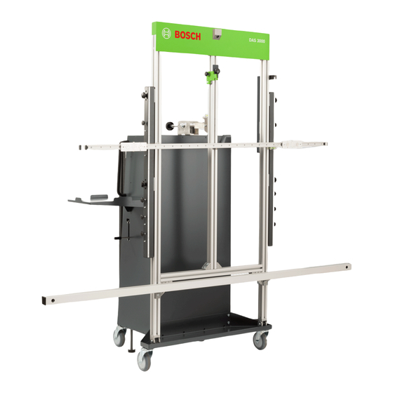
- Page 1 DAS 3000 Calibration and adjustment device Reparaturanleitung Kalibrier- und Justagevorrichtung Repair instructions Calibration and adjustment device...
-
Page 2: Table Of Contents
| 2 | DAS 3000 Benutzerhinweise............................Symbole in der Dokumentation........................Warnhinweise in der Dokumentation......................Zielgruppe..............................Mitgeltende Unterlagen..........................Benötigte Werkzeuge und Hilfsmittel......................Komponenten prüfen............................ Verschraubungen und Versiegelungen prüfen....................Kamera an DAS 3000 S10 prüfen... -
Page 3: Benutzerhinweise
Tod oder schwere Körperverletzung VORSICHT Mögliche gefährliche Situation Leichte Körperverletzung ---Separator--- Zielgruppe Die Instandsetzung von DAS 3000 dürfen nur Kundendienst-Techniker durchführen. ---Separator--- Mitgeltende Unterlagen • 1 689 989 444 - Originalbetriebsanleitung DAS 3000 • 1 689 973 484 - Ersatzteilliste DAS 3000 ---Separator--- Benötigte Werkzeuge und Hilfsmittel... -
Page 4: Komponenten Prüfen
Versiegelte Schrauben prüfen, welche die Libelle an der 2-Grad-Verstellung fixieren. Die Libelle wird ab Werk an DAS 3000 fein eingestellt. Wird die Verschraubung der Libelle gelockert und da‐ durch deren Position verändert, geht die Feineinstellung verloren. Die genaue Positionierung der Kalibrierta‐... - Page 5 Die Seriennummer befindet sich auf dem Typschild, das oberhalb der Halterung für Laptop/Tablet angebracht ist. 11. Linienlaser P-Assist S5 einschalten. 12. Referenztafel für Abstandsmessung mithilfe des Linienlasers mittig vor DAS 3000 in einem Abstand zwischen 2,40 bis 2,60 m positionieren. Die Referenztafel für die Abstandsmessung muss vollständig im Kamerabild sichtbar sein.
-
Page 6: Kameras An Das 3000 S20 Prüfen
| 6 | DAS 3000 Vorgehen bei erfolgreicher Prüfung Magnetischen Messbalken prüfen. Kalibriertafelsicherung prüfen. DUAL -Board und weitere Kalibriertafeln prüfen. Referenztafel für Abstandsmessung prüfen. Referenztafel für Ausrichtung auf die Fahrachse prüfen. Ausrichthilfe prüfen. -
Page 7: Kamerabalken Prüfen
Die Seriennummer befindet sich auf dem Typschild, das oberhalb der Halterung für Laptop/Tablet angebracht ist. 11. Linienlaser P-Assist S5 einschalten. 12. Referenztafel für Abstandsmessung mithilfe des Linienlasers mittig vor DAS 3000 in einem Abstand zwischen 6,90 m bis 7,10 m positionieren. Die Referenztafel für die Abstandsmessung muss vollständig in den Kamerabildern sichtbar sein. -
Page 8: Magnetischen Messbalken Prüfen
| 8 | DAS 3000 Maximaler Abstand zwischen elektronischer Wasserwaage und Kamerabalken: < 1,3 mm 4. Kamerabalken tauschen, falls Abstand zwischen elektronischer Wasserwaage und Kamerabalken ≥ 1,3 mm. (1) Kamerabalken (2) Elektronische Wasserwaage (3) Abstandslehre Magnetischen Messbalken prüfen 1. Beide Schlitten an rechten Rand der Laufschiene schieben. -
Page 9: Kalibriertafelsicherung Y Prüfen
DAS 3000 | 9 | de (1) Magnetischer Messbalken (2) Elektronische Wasserwaage (3) Abstandslehre Kalibriertafelsicherung Y prüfen 1. DUAL -Board in D-Position befestigen. 2. DUAL -Board mit Kalibriertafelsicherung Y fixieren. 3. Elektronische Wasserwaage an DUAL -Board anlegen und auf Neigung prüfen. - Page 10 Max. Abweichung der Neigung von linker zu mittlerer Strebe: ≤ 0,6° Vorgehen bei einer Abweichung der Neigung von mehr 0,6° Bei einer Abweichung von mehr als 0,6° an der linken oder rechten Strebe ist DAS 3000 stark beschädigt. Neuen DAS 3000 dem Kunden bereitstellen.
-
Page 11: Kalibriertafeln Prüfen
DAS 3000 | 11 | de Kalibriertafeln prüfen Kalibriertafel DUAL-Board prüfen 1. Kalibriertafeln auf optische Mängel und Verschmutzung des Kalibriermusters prüfen. 2. Anlageflächen reinigen. 3. Kantenschutz prüfen. 4. Elektronische Wasserwaage diagonal (von unterer linker Ecke zu oberer rechter Ecke) auf DUAL -Board positionie‐... -
Page 12: Kameras Am Kamerabalken Wechseln
| 12 | DAS 3000 (1) Adapterplatte mit Kamera (2) Führungsstifte der Adapterplatte (3) Hammermuttern (4) Schrauben (5) Positionierbohrungen 7. USB-Leitung an Kamera anschließen. 8. Vordere Abdeckung an Rahmen befestigen. Kameras am Kamerabalken wechseln Die Kamera darf nicht von der Adapterplatte entfernt werden. Die Kamera ist ab Werk auf der Adapterplatte montiert und als Baugruppe kalibriert. -
Page 13: Kamerabalken Wechseln
Kameras im Kamerabalken abziehen. 3. USB-Leitungen aus hinterer Profilnut des Kamerabalkens entfernen. 4. Position der Kameras im Kamerabalken merken. Wenn die Kameras am neuen Kamerabalken an der falschen Position befestigt werden, liefert DAS 3000 fal‐ sche Messwerte. 5. Schrauben an der Adapterplatte lösen. -
Page 14: Kalibriertafelsicherung Y Wechseln
| 14 | DAS 3000 (1) USB-Leitungen (2) Schrauben an Adapterplatte (3) Adapterplatte mit montierter Kamera 7. Senkschrauben an Halterungen für Kamerabalken lösen, die mithilfe einer Hammermutter den Kameabal‐ ken fixieren. 8. Kamerabalken anheben und entfernen. (1) Senkschrauben an Halterungen für Kamerabalken (2) Kamerabalken 9. -
Page 15: Rollen Wechseln
Keine Kalibriertafel ist am Rahmen positioniert. 3. Halteadapter an Haltebügel einhängen. 4. Falls vorhanden, Multi-Target-Shop von Fahrwagen entfernen. 5. Alle weiteren losen Objekte auf oder an DAS 3000 entfernen, dass nichts von DAS 3000 herunterfallen kann. 6. Abdeckblech unten im Fahrwagen entfernen. - Page 16 9. DAS 3000 durch eine zweite Person an Griffen des Fahrwagens sichern. 10. DAS 3000 über die gesamte Dauer der folgenden Schritte durch zweite Person sichern. 11. DAS 3000 mit Hubwerkzeug vorsichtig anheben, dass sich die Rollen maximal 2 cm über dem Boden befinden. 12. Schraube oben an Rolle fixieren.
-
Page 17: Bremse Wechseln
DAS 3000 | 17 | de Mit unterschiedlichen Rollen ist eine präzise Ausrichtung und ein gleichmäßiges Manövrieren von DAS 3000 nicht gewährleistet. Während der Frontkamera- oder Radarsensorkalibrierung kann es zu Fehlern kommen. 18. DAS 3000 absenken und Hubwerkzeug entfernen. 19. Abdeckblech unten im Fahrwagen befestigen. - Page 18 | 18 | DAS 3000 8. Neue Gleitlager in Haltewinkel und unten am Fahrwagen einsetzen. 9. Zugstange durch Haltewinkel und Öffnung unten am Fahrwagen führen. 10. Gummipuffer unten an Zugstange befestigen. 11. Griff an Zugstange befestigen. 12. Zugfeder mit Halterung an Zugstange befestigen.
- Page 19 Tools and aids needed..........................Checking components..........................Checking threaded connections and seals....................Checking the camera on the DAS 3000 S10....................Checking the cameras on the DAS 3000 S20....................Checking the camera beam.......................... Checking the magnetic indicator bar...
-
Page 20: User Instructions
Possible dangerous situation Minor injury ---Separator--- Target group Repair of the DAS 3000 may only be performed by service technicians. ---Separator--- Other applicable documents • 1 689 989 444 - Original instructions DAS 3000 • 1 689 973 484 - Spare parts list DAS 3000... -
Page 21: Checking Components
Check the sealed screws that secure the spirit level at the 2-degree setting. The spirit level is adjusted precisely on the DAS 3000 at the factory. If the threaded connection on the spirit level is loosened, allowing the position to change, the precise adjustment is lost. This prevents exact posi‐... - Page 22 The serial number is located on the type plate, which is attached above the mounting for the laptop/tablet. 11. Switch on the P-Assist S5 line laser. 12. With the aid of the line laser, center the reference board for the distance measurement in front of the DAS 3000 at a distance between 2.40 to 2.60 m.
-
Page 23: Checking The Cameras On The Das 3000 S20
Check for defective camera in the edge protection frame. Check the edge protection frame. Checking the cameras on the DAS 3000 S20 The cameras are checked with the aid of the service menu. Service menu password: ia4kd 1. Position the hammerhead nuts for the mounting in the profile slot of the edge protection frame. -
Page 24: Checking The Camera Beam
The serial number is located on the type plate, which is attached above the mounting for the laptop/tablet. 11. Switch on the P-Assist S5 line laser. 12. With the aid of the line laser, center the reference board for the distance measurement in front of the DAS 3000 at a distance between 6.90 m to 7.10 m. -
Page 25: Checking The Magnetic Indicator Bar
DAS 3000 | 25 | en Maximum gap between the electronic spirit level and camera beam: < 1.3 mm 4. Replace the camera beam if the gap between the electronic spirit level and camera beam ≥ 1.3 mm. (1) Camera beam... -
Page 26: Checking The Calibration Board Retainer Y
| 26 | DAS 3000 Checking the calibration board retainer Y 1. Secure the DUAL -Board in the D-position. 2. Secure the DUAL -Board with the calibration board retainer Y. 3. Place the electronic spirit level on the DUAL -Board and check for inclination. -
Page 27: Checking The Calibration Boards
Max. difference in inclination between left and center brace: ≤ 0.6° Procedure if difference in inclination exceeds 0.6° If the difference exceeds 0.6° at the left or right brace, the DAS 3000 is severely damaged. Provide the customer with a new DAS 3000. -
Page 28: Repair
| 28 | DAS 3000 Repair ---Separator--- Changing the camera on the edge protection frame The camera must not be removed from the adapter plate. The camera is mounted on the adapter plate at the factory and calibrated as an assembly. If the camera is removed from the adapter plate, the calibration is lost and the camera cannot be used. -
Page 29: Changing The Cameras On The Camera Beam
DAS 3000 | 29 | en Changing the cameras on the camera beam The camera must not be removed from the adapter plate. The camera is mounted on the adapter plate at the factory and calibrated as an assembly. If the camera is removed from the adapter plate, the calibration is lost and the camera cannot be used. -
Page 30: Changing The Camera Beam
4. Note the position of the cameras in the camera beam. If the cameras are fastened in the wrong position on the new camera beam, the DAS 3000 provides incorrect measured values. -
Page 31: Changing The Calibration Board Retainer Y
DAS 3000 | 31 | en (1) Countersunk bolts for camera beam mountings (2) Camera beam 9. Remove the two loose hammerhead nuts from the lower profile slot in the camera beam. 10. Secure the removed countersunk bolt to the camera beam mountings by means of hammerhead nuts. -
Page 32: Changing The Rollers
3. Place the mounting adapter on the handle. 4. If present, remove Multi-Target-Shop from the trolley. 5. Remove all other loose objects on or around the DAS 3000 so that nothing can fall off the DAS 3000. 6. Remove the cover plate at the bottom of the trolley. -
Page 33: Changing The Brake
10. Have a second person secure the DAS 3000 over the entire duration of the following steps. 11. Carefully lift the DAS 3000 by means of the lifting tool so that the rollers are at most 2 cm over the floor. - Page 34 | 34 | DAS 3000 3. Unscrew the handle from the draw bar. 4. Remove tension spring with mounting from the draw bar and the trolley. 5. Remove rubber buffer from the draw bar. 6. Pull out the draw bar (5).
- Page 35 DAS 3000 | 35 | en 13. Attach tension spring to the trolley. 14. Fasten the cover plate in the bottom of the trolley. Robert Bosch GmbH 1 689 975 292 | 2020-05-04...
- Page 36 | 36 | DAS 3000 Robert Bosch GmbH Franz-Oechsle-Str. 4 73207 Plochingen Deutschland www.bosch.com bosch.prueftechnik@bosch.com 1 689 975 292 | 2020-05-04 1 689 975 292 | 2020-05-04 Robert Bosch GmbH...
Need help?
Do you have a question about the DAS 3000 and is the answer not in the manual?
Questions and answers