Chapters
Table of Contents

Subscribe to Our Youtube Channel
Related Manuals for Bosch WBE 4200


Summary of Contents for Bosch WBE 4200
- Page 1 WBE 4200 de Instandsetzungsanleitung en Repair instructions es Instructions de réparation Reifenmontiermaschine Tire changer Machine à monter les pneus it Istruzioni di riparazione Smontagomme...
- Page 2 2 | WBE 4200 | 1 695 600 091 2012-11-16 Robert Bosch GmbH...
- Page 3 | WBE 4200 | 3 Inhaltsverzeichnis Deutsch Contents English Índice Español Indice Italiano Robert Bosch GmbH 1 695 600 091 2012-11-16...
-
Page 4: Table Of Contents
4 | WBE 4200 | Inhaltsverzeichnis 10.4.5 Kalibrierung elektronischer Messschieber Verwendete Symbolik 10.4.3 WBE 4200 kalibrieren In der Dokumentation 10.4.4 Kontrollmessung 1.1.1 Warnhinweise – Aufbau und Bedeutung 5 10.5 Factory-Kalibrierung 1.1.2 Symbole – Benennung und Bedeutung 5 10.5.1 Aufruf Kalibriermenü... -
Page 5: Verwendete Symbolik
Verwendete Symbolik | WBE 4200 | 5 Verwendete Symbolik Auf dem Produkt In der Dokumentation Alle Warnzeichen auf den Produkten beachten und in 1.1.1 Warnhinweise – Aufbau und Bedeutung lesbarem Zustand halten! Warnhinweise warnen vor Gefahren für den Benutzer oder umstehende Personen. Zusätzlich beschreiben 1.2.1... -
Page 6: Warnhinweise
6 | WBE 4200 | Verwendete Symbolik 1.2.2 Warnhinweise GEFAHR – Stromführende Teile beim Öffnen von WBE 4200! Verletzungen, Herzversagen oder Tod durch Stromschlag beim Berühren von stromführenden Teilen (z. B. Hauptschalter, Leiterplatten). ¶ An elektrischen Anlagen oder Betriebsmitteln dürfen nur Elektrofachkräfte oder unterwiesene... -
Page 7: Benutzerhinweise
In diesem Fall kann vom Betreiber verlangt werden, angemessene Maßnahmen durchzuführen. Voraussetzungen WBE 4200 muss auf einem ebenen Boden aus Beton oder ähnlichem Material aufgestellt und verankert werden. Unebener oder schwingender Untergrund kann zu Ungenauigkeiten beim Messen der Unwucht führen. -
Page 8: Wbe 4200
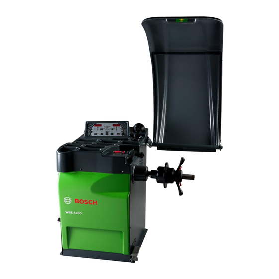
8 | WBE 4200 | Benutzerhinweise WBE 4200 Fig. 1: WBE 4200 Pos. Denominazione Funzioni Bedienfeld Bedienung WBE 4200, siehe Messschieber R Felgenabstand und Felgendurchmesser erfassen. R Positionen zur Befestigung der Klebegewichte ermitteln. (elektronisch) Radschutzhaube R Schutz des Bedieners vor wegfliegenden Partikeln (z. B. Schmutz, Wasser). - Page 9 Benutzerhinweise | WBE 4200 | 9 Robert Bosch GmbH 1 695 600 091 2012-11-16...
-
Page 10: Bedienung
10 | WBE 4200 | Bedienung Bedienung Bedientasten Nach dem Einschalten von WBE 4200 wird im Bedienfeld/Anzeigefeld in den Displays einige Sekunden lang die Softwareversion angezeigt. Danach werden die Werte links und rechts im Display angezeigt. Display Fig. 3: Taste... -
Page 11: Menünavigation
Menünavigation | WBE 4200 | 11 Menünavigation ON = Funktion zur automatischen Erkennung des Auswuchtungsprogramms aktiv. Das Menü der Auswuchtmaschine kann in verschiedene OFF = Funktion zur automatischen Erkennung des Untermenüs untergliedert werden: Auswuchtungsprogramms nicht Einstellungen für den Betrieb aktiv. -
Page 12: Kalibrierung
12 | WBE 4200 | Menünavigation Kalibrierung HINWEISE FÜR DIE WARTUNG In der folgenden Tabelle werden die für die Modelle WBE 4200 typischen Einstellungen genannt: Die Taste <MENÜ> fino alla scritta CAL gedrückt halten, bis eingeblendet wird, anschließend die Taste <NUTZER>... -
Page 13: Selbstkalibrierung
Menünavigation | WBE 4200 | 13 5.3.1 Selbstkalibrierung Display LI Display RE Beschreibung Die Taste <MENÜ> bis zum Eintrag t5t drücken und FELGENABSTAND Die Taste < > dann zum Aufrufen des Untermenüs innerhalb 1,5 drücken, um durch das Menü zu Sekunden die Taste <NUTZER>... -
Page 14: Betriebsstörungen Und Fehlercodes
14 | WBE 4200 | Betriebsstörungen und Fehlercodes Betriebsstörungen und Fehlercodes Während des Betriebs der Radwuchtmaschine können verschiedene Ursachen für Betriebsstörungen auftreten, die nach ihrer Erfassung durch den Mikroprozessor auf dem Display mit der Meldung „Er“, gefolgt von einer Nummer zur Erklärung der Bedeutung, angezeigt werden. - Page 15 Betriebsstörungen und Fehlercodes | WBE 4200 | 15 Fehlercode Betriebsstörung Ursachen und mögliche Abhilfemaßnahmen Die Phasendifferenz zwischen den beiden R Sicherstellen, dass das Kalibrierungsge- Err7 Messsensoren ist zu groß. wicht korrekt angebracht wurde. R Die korrekte Befestigung der Radwuchtmaschine über- prüfen: unter Umständen ist die Befestigung nicht sta-...
-
Page 16: Eigendiagnose-Menü
16 | WBE 4200 | Eigendiagnose-Menü Eigendiagnose-Menü erfassen die Schwingungen und wandeln die erfasste Alle Modelle der Radwuchtmaschinen von BOSCH Vibration in elektrische Spannung um. verfügen über ein Eigendiagnose-Menü, das bei der Durchführung von Wartungseingriffen zum Zweck einer eingehenden Prüfung der Maschine verwendet werden kann. -
Page 17: Encoder)
Eigendiagnose-Menü | WBE 4200 | 17 Display LI Display RE Beschreibung Zeigt die Position des Encoders von 0 bis 199 an HINWEISE FÜR DIE WARTUNG: Eine Betriebsstörung der Vorrichtung wird automatisch vom Programm erfasst, das auf dem Display die Meldung... - Page 18 18 | WBE 4200 | Eigendiagnose-Menü La ruota non Die Leistungskarte kontrollieren und sich der Wert bei Ruhestellung auf der Hälfte der frena (in contro eventuell auswechseln. Leseskala befindet; corrente) Den Kondensator überprüfen und ggf. sich der Wert bei Abwärtsbewegung der Welle in ersetzen.
- Page 19 Eigendiagnose-Menü | WBE 4200 | 19 Es wird ein Unterschied Die Messsensoren neu Der Wert bleibt zwischen 40 Kontrollieren, dass der Ring zwischen den beiden positionieren. und 4095 blockiert. richtig befestigt ist. Ruhewerten festgestellt: z.B. Den Messsensor Das Anschlusskabel innerer Sensor 2050 (Werte auswechseln (in unserem auswechseln.
- Page 20 20 | WBE 4200 | Eigendiagnose-Menü ACHTUNG: Falls sich der Gewindestift lockert und das Potentiometer nicht mehr ordnungsgemäß an Mit der Abkürzung wird die Funktion bezeichnet, der Welle befestigt ist, liest die Vorrichtung keinen die direkt die digitalen Eingänge steuert. Um Wert mehr und der Schieber der Potentiometer in der Funktion zu blättern, wird die Taste...
- Page 21 Eigendiagnose-Menü | WBE 4200 | 21 Durch Anwahl der Funktion können mit der Taste +/- die Funktionen des Magnets und demzufolge die Sperrung des Easyfix-Tasters in Position überprüft werden. Option für diese Maschine nicht verfügbar 7.8.4 Elektromagnetbremse Durch Anwahl der Funktion und Drücken der...
-
Page 22: Austauscharbeiten
22 | WBE 4200 | Austauscharbeiten Austauscharbeiten 9. den neuen Messsensor einbauen; Ersatz des Pick-ups 1. die Abdeckung mit der Gewichteablage abmontieren; Fig. 12: damit die Kugeln an ihrer Position bleiben, etwas Fett verwenden; den Gewindestift solange wieder eindrehen, bis er sich nicht mehr von Hand bewegen lässt (Abb.14, pos.1):... -
Page 23: Auswechslung Alueasy® Lehre
Austauscharbeiten | WBE 4200 | 23 Auswechslung AluEasy® Lehre Auswechslung des Antriebsriemens 1. die Abdeckung mit der Gewichteablage abmontieren; 1. die Abdeckung mit der Gewichteablage abmontieren; 2. Das Action-centre trennen; 2. Die mittlere Mittungsflansche (Abb.20, Pos.1) 3. Die Blockierschraube des Sensors abschrauben abnehmen und, nachdem die drei Schrauben (Abb.15,pos.1);... -
Page 24: Auswechslung Der Leistungskarte
24 | WBE 4200 | Austauscharbeiten Schraube (Abb.21, Pos.2) soweit ausgeschraubt werden, dass sie den Riemen sich zu lockern erlauben; Fig. 20: 3. die Karte auswechseln und die Anschlüsse wiederherstellen. Fig. 21: Fig. 19: 4. die Riemenspannung regulieren (durch Anziehen der Einstellschraube), bis eine manuelle 90°-Drehung... -
Page 25: Verfahren Zur Auswechslung Der Video-Karte
Austauscharbeiten | WBE 4200 | 25 Verfahren zur Auswechslung der Video-Karte 1. Das Gehäuse an der linken Seite und das vordere entfernen; 2. die Karte auswechseln und die Anschlüsse wiederherstellen. 3. die Konfiguration der Karte vornehmen HINWEISE FÜR DIE WARTUNG: Falls die Karte ausgewechselt werden muss müssen... -
Page 26: Einstellarbeiten
26 | WBE 4200 | Einstellarbeiten Einstellarbeiten Prozedur für die Positionierung des Potentio- meters für die Durchmessermessung: Prozedur für die Positionierung des Potentiometers für die Breitenmes- 1. nur die Gewichteablage-Abdeckung entfernen, ohne dabei die Karte abzutrennen; sung: 2. die Auswuchtmaschine starten;... -
Page 27: 10. Instandhaltung
Aufkleber Drehrichtung Rad 1695653878 Die Kalibrierung ist im Kapite10.4 beschrieben. Tab. 5: Ersatz- und Verschleißteile Wir empfehlen, WBE 4200 im Rahmen der Wartung 10.3 Empfohlene Ersatzteile und Werkzeuge und Pflege (halbjährlich), bei einem Wechsel des Flansches oder bei ungenauen Messergebnissen in Für eine richtige Wartung unentbehrliche Werkzeuge:... -
Page 28: Kalibrierung
28 | WBE 4200 | Instandhaltung 10.4 Kalibrierung Wir empfehlen, WBE 4200 im Rahmen der Wartung und Pflege (halbjährlich), bei einem Wechsel des Flansches oder bei ungenauen Messergebnissen in folgender Reihenfolge zu kalibrieren: 1. Flansch kalibrieren. 2. Messschieber kalibrieren. Fig. 26: 3. WBE 4200 kalibrieren. -
Page 29: Wbe 4200 Kalibrieren
Instandhaltung | WBE 4200 | 29 Bei der Kalibrierung der Felgendaten muss der Griff 10.4.3 WBE 4200 kalibrieren des elektronischen Messschiebers richtig gehalten werden, um Fehler beim Auswuchten zu vermeiden. 1. Kalibriermenü aufrufen. 2. <MENU>-Taste drücken, bis C-2 im linken Display erscheint. -
Page 30: Kontrollmessung
Auswuchtgewicht von z. B. 60 g auf eine der beiden Seiten anbringt. 5. Radschutzhaube schließen. Messung wird gestartet. WBE 4200 muss auf dieser Seite genau diese Unwucht (Wert und Position) anzeigen. Für die andere Seite darf die Angabe höchstens 5 g betragen. -
Page 31: Factory-Kalibrierung
Instandhaltung | WBE 4200 | 31 10.5 Factory-Kalibrierung Wir raten, die Factory-Kalibrierung beim Auswechseln der Pick-up, der Messgruppe oder der Karte vorzunehmen, wobei folgende Sequenz einzuhalten ist: 1. Flanschkalibrierung 2. Kalibrierung der elektronischen Schieblehre 3. Kalibrierung mit Probegewicht Fig. 31: Am Ende jeder Kalibrierung muss eine Kontrollmessung durchgeführt werden. -
Page 32: 11. Elektrische Anlage
32 | WBE 4200 | Elektrische Anlage 11. Elektrische Anlage 1 695 600 091 2012-11-16 Robert Bosch GmbH... - Page 33 Elektrische Anlage | WBE 4200 | 33 Robert Bosch GmbH 1 695 600 091 2012-11-16...
- Page 34 34 | WBE 4200 | Contents Symbols used In the documentation 1.1.1 Warning notices - 7.8.1 Protection micro switch Structure and meaning 7.8.2 Pedals 1.1.2 Symbols in this documentation 7.8.3 Easyfit® magnet On the product 7.8.4 Electromagnetic brake 1.2.1 Product information 1.2.2...
-
Page 35: Symbols Used
Symbols used | WBE 4200 | 35 Symbols used On the product In the documentation Observe all warning notices on products and ensure 1.1.1 Warning notices - Structure and meaning they remain legible! Warning notices warn of dangers to the user or people in the vicinity. -
Page 36: Warning Indications
36 | WBE 4200 | Symbols used 1.2.2 Warning indications DANGER – Exposure of live parts on opening the WBE 4200! Risk of (fatal) injury or heart failure from electric shocks on contact with live components (e.g. master switch, printed circuit boards). -
Page 37: User Information
10" - 27" and a rim width of 1" - 20". Bosch Tire Service Equipment". These instructions must The WBE 4200 is to be used exclusively for this purpose be carefully studied prior to start-up, connection and and solely for the range of applications specified in operation of the WBE 4200 and must always be heeded. -
Page 38: Wbe 4200
38 | WBE 4200 | User information WBE 4200 Fig. 1: WBE 4200 Item Designation Function/purpose Control panel Operation of WBE 4200 R Recording of rim distance and rim diameter. Vernier caliper (electronic) R Determination of positions for attachment of adhesive weights. -
Page 39: Operation
Operation | WBE 4200 | 39 Operation Control keys After switching on the WBE 4200 the software version appears on the displays of the control/ display panel for a few seconds. The 0 values are then shown on the left and right of the display. -
Page 40: Menu Navigation
You can access the sub-menu by releasing the <MENU> key. NOTES FOR THE ASSISTANCE: <MENU> - SET Here you are the settings belonging to the WBE 4200 " Using <MENU>, you can surf the menu version: "... -
Page 41: Firmware Updating Procedure
*)Option not available for WBE 4200 flange and shaft Setting up of the wheel size and NOTES FOR THE ASSISTANCE: memorization of the unbalance Here you are the settings belonging to the WBE 4200 version: 5.3.2 Calibrating the electronic vernier caliper Left Display... -
Page 42: Auto-Diagnosis
42 | WBE 4200 | Menu navigation 5.3.4 Auto-diagnosis Left Display Right Display Description Press the <MENU> key until you see the word t5t and Digital entries: press the < DISTANCE then access the sub-menu by pressing the <USER> key >... -
Page 43: Problems And Error Codes
Problems and error codes | WBE 4200 | 43 Problems and error codes During the working of the balancing machine, there can be several problems If the microprocessor detects them, they appear on the display through the notice Err followed by a number which stands for the meaning. - Page 44 44 | WBE 4200 | Problems and error codes Error code Problems Causes and possible solutions Err9 The external pick-up is not connected or R Check and substitute the right pick-up. (Chapter 9.5). defective. Err10 Defect of the position detectors in the R Verify the connection of the optoelectronic device.
-
Page 45: Auto-Diagnosis Menu
Auto-diagnosis menu | WBE 4200 | 45 Auto-diagnosis menu On every Bosch balancing machine, you can find an auto-diagnosis menu that you can use during the assistance in order to check the machine very carefully. 1. Keep the <MENU> key pressed. -
Page 46: Encoder)
46 | WBE 4200 | Auto-diagnosis menu In order to monitor if the pick-ups work correctly, follow these instructions: 4. mount a test wheel on the machine (14-15” of iron) and balance it perfectly; 5. apply a single test weight outside (for example 60g) and make a test launch. -
Page 47: Check Belt Tensioning
Auto-diagnosis menu | WBE 4200 | 47 ¶ If the wheel does not turn listen if, by activating the if you lift the shaft up, the value increases up to the cycle, a "click" from the relays is emitted from the end of the scale. -
Page 48: Signal Of The Potentiometer Of The Width
48 | WBE 4200 | Auto-diagnosis menu ¶ In order to check the correct functioning of the 7.4.6 6 - Signal of the potentiometer of the diameter potentiometer, pull out the gauge and check that during the stroke the value does not get blocked. -
Page 49: Tar
Auto-diagnosis menu | WBE 4200 | 49 7.8.3 Easyfit® magnet Left Display Right Display Description Press <RIM DISTANCE> to roll down the menu By selecting the MAG function and pressing the +/- key, the magnet functions are checked, therefore of the blocking of the easyfix tester in position. -
Page 50: Replacement Interventions
50 | WBE 4200 | Replacement interventions Replacement interventions Pick-up replacement 1. Remove the weights protection; Fig. 12: To keep the spheres in position, use a little of oil grease; 10. Screw the nut until you cannot turn it manually;... -
Page 51: Replacement Easyfit® Calliper
Replacement interventions | WBE 4200 | 51 Replacement Easyfit® calliper Engine belt replacement 1. Remove the weights protection; 1. Remove the weights protection; 2. Disconnect the Control panel; 2. Remove the central centring flange (fig.20, pos.1) 3. Loosen the fixing screw of the feeler (fig.15, pos.1);... -
Page 52: Power Board Replacement
52 | WBE 4200 | Replacement interventions Power board replacement 1. Remove the weights protection; 2. Loosen the 5 rear screws using an allen wrench; Fig. 20: 3. replace the board and restore connections. Fig. 19: Belt replacement Fig. 21: 4. Remove the belt of the motor by loosening the three... -
Page 53: Cpu Board Replacement Procedure
Replacement interventions | WBE 4200 | 53 CPU board replacement procedure 1. Remove the upper protections; 2. Replace the board and restore connections; 3. Configure the board. NOTES FOR THE ASSISTANCE When you need to substitute the board, remember to set up the correct configurations (5.2) and complete... -
Page 54: Adjustment Interventions
54 | WBE 4200 | Adjustment interventions Adjustment interventions Diameter potentiometer positioning Distance potentiometer positioning 1. Remove only the carter without disconnecting the board; 1. Remove the left side protection without 2. Start the balancing machine; disconnecting the board; 3. Enter the test menu;... -
Page 55: 10. Maintenance
Suggested spare partsi Il costruttore non risponde di eventuali danni dovuti 10.1 Cleaning and servicing all’impiego di ricambi non originali. Before cleaning and servicing, switch off WBE 4200 Designation Item and disconnect mains plug. Alternating-Current Motor 110/50 1695043191 Alternating-Current Motor 230/ 1695655605 Do not use any solvent-based cleaning agents. -
Page 56: Standard Calibration
56 | WBE 4200 | Maintenance 10.4 Standard Calibration 10.4.3 Calibrating the electronic vernier caliper As part of service and upkeep (every six months), on 1. Press the <MENU> button until CAL appears in the flange replacement or in the event of measurement left-hand display. -
Page 57: Wbe 4200 Calibration
Maintenance | WBE 4200 | 57 10.4.4 WBE 4200 calibration 1. Call up the calibration menu; 2. Press the <MENU> key until C-2 appears on the left- hand display. 3. Attach a motor vehicle wheel of medium size (e.g. rim width 5.5", rim diameter 14") and in very good condition to the flange. -
Page 58: Reference Measurement
Sound and automatic start are active in the following Measurement commences. description. The WBE 4200 must display precisely this unbalance (value and position) on this side. The value indicated 1. Press and hold the <MENU> key. for the other side must not exceed 5 g. -
Page 59: Calibration With Sample Weight
Maintenance | WBE 4200 | 59 " 10.5.4 Calibration with sample weight Calibration is completed. After Calibration of electronic vernier caliper remove The performed calibration is automatically and the wheel from machine. permanently saved. After having carried out factory calibration with 1. -
Page 60: 11. Electric System
60 | WBE 4200 | Electric system 11. Electric system 1 695 600 091 2012-11-16 Robert Bosch GmbH... - Page 61 Electric system | WBE 4200 | 61 Robert Bosch GmbH 1 695 600 091 2012-11-16...
- Page 62 62 | WBE 4200 | Índice 7.8.3 Imán ALUDATA® 7.8.4 Freno electromagnético Símbolos empleados En la documentación 7.10 ILL 1.1.1 Advertencias: estructura y significado 63 1.1.2 Símbolos en esta documentación Operaciones de sustitución En el producto Procedimiento ajuste o sustitución pick-up: 1.2.1...
-
Page 63: Símbolos Empleados
Símbolos empleados | WBE 4200 | 63 Símbolos empleados En el producto En la documentación Tenga en cuenta todas las indicaciones de adverten- 1.1.1 Advertencias: estructura y significado cia en los productos y manténgalas bien legibles. Las indicaciones de advertencia advierten de peligros para el usuario o las personas circundantes. -
Page 64: Indicaciones De Advertencia
En las instalaciones o utillajes eléctricos deben trabajar sólo electricistas o per- sonas debidamente capacitadas bajo la supervisión de un electricista. ¶ Antes de abrir WBE 4200, separarlo de la red de tensión. 1 695 600 091 2012-11-16 Robert Bosch GmbH... -
Page 65: Indicaciones Para El Usuario
(B - C) Compatibilidad electromagnética (CEM) La WBE 4200 cumple los criterios de la Directriz de Compatibilidad Electromagnética 2004/108/EG. La WBE 4200 es un producto de la clase/categoría A según EN 61 326. La WBE 4200 puede provocar interferencias de alta frecuencia (perturbaciones radioeléctricas) en las zonas residenciales, que pue-... -
Page 66: Wbe 4200
66 | WBE 4200 | Indicaciones para el usuario WBE 4200 Fig. 1: WBE 4200 Pos. Denominazione Funzioni Campo de manejo Manejo WBE 4200, ver Cap. 7 R Registrar la distancia de llanta y el diámetro de la llanta. Corredera de medición R Determinar las posiciones para la fijación de los pesos pegados. -
Page 67: Manejo
Manejo | WBE 4200 | 67 Manejo Teclas de manejo Tras encender el WBE 4200 se muestra durante algu- nos segundos en la pantalla del campo de manejo/ campo de visualización la versión de software. Luego se muestran los valores 0 a izquierda y derecha en la pantalla. -
Page 68: Navegación Menú
68 | WBE 4200 | Navegación menú Navegación menú ON = activa la función de reconoci- miento automático del programa de Se puede subdividir el menú de la equilibradora en di- equilibrado. versos sub-menús: OFF = = no activa la función de re- conocimiento automático del pro-... -
Page 69: Calibración
Navegación menú | WBE 4200 | 69 NOTAS PARA LA ASISTENCIA: 5.2.2 Calibración En la tabla siguiente se muestran las regulaciones ca- Presione la tecla <MENÚ> hasta que aparezca el texto racterísticas de los modelos WBE 4200: CAL y luego la tecla <USUARIO>. -
Page 70: Auto-Diagnosis
70 | WBE 4200 | Navegación menú 5.2.3 Auto-diagnosis Display IZQ Display DCHA Descripción Presione el pulsador <MENÚ> hasta que aparezca el Entradas digitales: pulsar la te- cla <DISTANCIA DE LLANTA> mensaje t5t y luego, para acceder al submenú, presione para desplegar el menú... -
Page 71: Averias Y Códigos De Errores
Averias y códigos de errores | WBE 4200 | 71 Averias y códigos de errores Durante el funcionamiento de la máquina puede haber diversas averias que, si son identificadas por el microproce- sador, aparecen en la pantalla con la palabra “Er” seguida de un número que indica el significado. - Page 72 72 | WBE 4200 | Averias y códigos de errores Codigo error Averias Causas y posibles remedios Err8 El pick-up interno está desconectado o defec- R Comprobar o sustituir el pick-up interno (cap. 9.5). tuoso. Err9 El pick-up externo está desconectado o defec- R Comprobar o sustituir el pick-up externo (cap.
-
Page 73: Menú De Auto-Diagnosis
Menú de auto-diagnosis | WBE 4200 | 73 Menú de auto-diagnosis En todas las versiones de equilibradoras BOSCH se pre- senta un menú de auto-diagnosis que puede ser utiliza- do en fase de asistencia para controlar en profundidad el aparato. -
Page 74: Encoder)
74 | WBE 4200 | Menú de auto-diagnosis La máquina no Comprobar que el encoder esté conec- Para valorar el buen funcionamiento de los pick-up pro- cuenta ningún tado. ceder del siguiente modo: espacio. Sustituir el encoder. 4. montar en la máquina una rueda de prueba (14-15”... -
Page 75: 0_10 (Analógicos)
Menú de auto-diagnosis | WBE 4200 | 75 0_10 (Analógicos) Página para el control de las entradas analógicas. Desde este menú es posible leer directamente la señal que llega de los sensores (pick-up y potenciómetros), de forma que se pueda indentificar la causa de un po- sible defecto. -
Page 76: Señal Del Potenciómetro De La Anchura
76 | WBE 4200 | Menú de auto-diagnosis Diagnóstico del potenciómetro de la distancia (4) ATENCIÓN : si casualmente se afloja la tuerca y se descuelga el potenciómetro del eje, el aparato no lee más ninguna medida porque el carro de los poten- Defecto Corrección... -
Page 77: Microinterruptor De La Cubierta
Menú de auto-diagnosis | WBE 4200 | 77 6. pulsar la tecla <SET>hasta que aparezca escrito Display IZQ Display DCHA Descripción después la tecla MM/INCH; Estado del cárter: OFF abierto, on / oFF ON cerrado 7. pulsar <SET> hasta que aparezca escrito on / oFF Test electroválvula brida... -
Page 78: Operaciones De Sustitución
78 | WBE 4200 | Operaciones de sustitución Operaciones de sustitución 7. aflojar la tuerca de bloqueo situada debajo del pick- Procedimiento ajuste o sustitución 8. desatornillar la tuerca de posición; pick-up: 9. si es necesario introducir el pick-up nuevo;... -
Page 79: Sustitución Del Calibre Easyfit
Operaciones de sustitución | WBE 4200 | 79 Sustitución del calibre Easyfit® Sustitución de la correa del motor 1. Quite la cubierta portapesos; 1. Quite la cubierta portapesos; 2. desconecte el action-centre; 2. Quite la brida de equilibrado central (fig. 16, pos. -
Page 80: Procedimiento De Sustitución De La Tarjeta Potencia
80 | WBE 4200 | Operaciones de sustitución 3. cambie la tarjeta y restablezca las conexiones. Fig. 21: Fig. 19: 1. CN3 - Microinterruptor de la cubierta 2. CN4 - cable por CPU 4. Regule la tensión de la correa (enroscando el tornillo 3. -
Page 81: Sustitución Tarjeta
Operaciones de sustitución | WBE 4200 | 81 Sustitución tarjeta 1. Quitar el único cárter portapesos 2. Con una llave Allen desatornille los 5 tornillos poste- riores; 3. cambie la tarjeta y restablezca las conexiones. NOTA PARA LA ASISTENCIA Cuando se presenta la necesidad de sustituir la tarjeta recordar establecer las correctas configuraciones y hacer todo el proceso de medición. -
Page 82: Intervenciones De Regulación
82 | WBE 4200 | Intervenciones de regulación Intervenciones de regulación Procedimiento colocación potenció- metro diámetro; Procedimiento colocación potencime- tro distancia: 1. quitar el único cárter portapesos sin desconectar la tarjeta; 1. quitar el único cárter portapesos sin desconectar la 2. encender la equilibradora;... -
Page 83: 10. Mantenimiento
Antes de la limpieza y el mantenimiento, desconectar Denominación Número de n° el WBE 4200 y desempalmar el enchufe de red. pedido Motor Corriente Alterna 110/50 1695043191 No utilizar agentes limpiadores que contengan Motor Corriente Alterna 230/ 1695655605 diluyentes. -
Page 84: Calibración
10.4 Calibración Display IZQ Display Descripción DCHA Se aconseja realizar la calibración de WBE 4200 Memorización del grupo cero bri- da y eje en el marco de las operaciones de mantenimiento Introducción dimensiones rueda y semestrales; en caso de sustitución de la brida o en memorización del desequilibrio... -
Page 85: Calibración Wbe 4200
Mantenimiento | WBE 4200 | 85 9. Introducir el valor "200" mediante <-> o <+>. 10.4.4 Calibración WBE 4200 10. C onfirmar con la tecla < (Fig. DISTANCIA DE LLANTA> 7.2). 1. Llamar el menú de calibración. En la pantalla izquierda se muestra H-1. -
Page 86: Medición De Control
5. Cerrar la cubierta protectora de la rueda. Se inicia la medición. El WBE 4200 debe indicar en ese lado exacta- mente ese desequilibrio (valor y posición). Para el otro lado, la indicación debe ser, como máx. de 5 g. -
Page 87: Calibración Factory
Mantenimiento | WBE 4200 | 87 10.5 Calibración factory 2. Vuelva a poner el pie de rey en posición de reposo. Se recomienda efectuar la calibración factory al actualizar el software, al efectuar la sustitución de los sensores pick-up, del grupo de medida o de la tarjeta, ateniéndose a la siguiente secuencia:... -
Page 88: 11. Instalación Eléctrica
88 | WBE 4200 | Instalación eléctrica 11. Instalación eléctrica 1 695 600 091 2012-11-16 Robert Bosch GmbH... - Page 89 Instalación eléctrica | WBE 4200 | 89 Robert Bosch GmbH 1 695 600 091 2012-11-16...
- Page 90 90 | WBE 4200 | Indice Simboli utilizzati 7.8.3 Magnete Easyfit® Nella documentazione 7.8.4 Freno elettromagnetico 1.1.1 Indicazioni di avvertimento – struttura e significato 7.10 ILL 1.1.2 Simboli nella presente documentazione Interventi di sostituzione Sul prodotto Sostituzione dei pick-up 1.1.1 Informazioni presenti sul prodotto Sostituzione calibro Easyfit®...
-
Page 91: Simboli Utilizzati
Simboli utilizzati | WBE 4200 | 91 Simboli utilizzati Sul prodotto Nella documentazione Rispettare tutti i simboli di avvertimento sui prodotti 1.1.1 Indicazioni di avvertimento – e mantenere le relative etichette integralmente in struttura e significato condizioni di perfetta leggibilità! Le indicazioni di avvertimento mettono in guardia dai 1.1.1... - Page 92 92 | WBE 4200 | Simboli utilizzati PERICOLO – presenza di parti sotto corren- te all’apertura di WBE 4200! Lesioni, arresto cardiaco o morte dovuti a scossa elettrica in caso di contatto con parti sotto corrente (ad es. interruttore principale, schede a circuito stampato).
-
Page 93: Istruzioni Per L'utente
1" - 20"*. vanno lette attentamente prima della messa in funzione, WBE 4200 deve essere impiegata esclusivamente per lo del collegamento e dell‘uso di WBE 4200 e devono es- scopo specificato e solo negli ambiti di funzionamento sere assolutamente rispettate. -
Page 94: Wbe 4200
94 | WBE 4200 | Istruzioni per l‘utente WBE 4200 Fig. 1: WBE 4200 Pos. Denominazione Funzioni Pannello di comando/ R Comando WBE 4200. R Visualizzazione software (valori di misura e avvertenze sull’uso) pannello di visualizzazione Calibro a corsoio R Rilevare la distanza del cerchione e il diametro del cerchione. -
Page 95: Struttura Del Programma
Struttura del programma | WBE 4200 | 95 Struttura del programma Tasti di comando Dopo l’accensione della WBE 4200 nel pannello di comando/pannello di visualizzazione viene visualizzato nei display per alcuni secondi la versione del software. Dopodiché entrambi i display indicano il valore 0. -
Page 96: Navigazione Menù
96 | WBE 4200 | Navigazione menù Navigazione menù ON = attiva la funzione riconosci- mento automatico del programma di equilibratura. Si può suddividere il menù dell'equilibratrice in diversi OFF = non attiva la funzione ricono- scimento automatico programma di sottomenù:... -
Page 97: Procedura Aggiornamento Firmware
Navigazione menù | WBE 4200 | 97 Calibrazione NOTE PER L’ASSISTENZA: Premere il tasto <MENU> fino alla scritta CAL poi il tas- Nella tabella seguente sOno riportati i settaggi caratte- ristici del modello WBE 4200: to <UTENTE> <MENU> - SET - CAL - <UTENTE>... -
Page 98: Auto-Diagnosi
98 | WBE 4200 | Navigazione menù Auto-diagnosi Display SX Display DX Descrizione Premere il tasto <MENU> fino alla scritta TST e poi per Ingressi digitali: premere il tasto <DISTANZA CERCHIonE> accedere al sottomenù premere il tasto <UTENTE> ent- per scorrere il sottomenù... -
Page 99: Malfunzionamenti E Codici Di Errore
Malfunzionamenti e codici di errore | WBE 4200 | 99 Malfunzionamenti e codici di errore Durante il funzionamento della macchina ci possOno essere diverse cause di malfunzionameno che, se rilevate dal microprocessore, vengOno indicate sul display cOn la dicitura Err seguito da un numero che ne indica il significato . - Page 100 100 | WBE 4200 | Malfunzionamenti e codici di errore Malfunzionamenti Codice errore Cause e possibili rimedi Err10 Difetto dei rivelatori della posizione R Verificare il collegamento della scheda optoelettrOnica. R Verificare che la scheda optoelettrOnica sia protetta dalla luce nell’optoelettrOnica.
-
Page 101: Menù Di Auto-Diagnosi
Menù di auto-diagnosi | WBE 4200 | 101 Menù di auto-diagnosi Su tutte le versioni di equlilibratrici Bosch è presente un menù di auto-diagnosi che può essere utilizzato in fase di assistenza per cOntrollare in modo approfOndi- l'apparecchiatura. 1. Premere e tenere premuto il tasto <MENU>. -
Page 102: Encoder)
102 | WBE 4200 | Menù di auto-diagnosi Per valutare il buOn funzionamento dei pick-up proce- dere nel seguente modo: 4. mOntare sulla macchina una ruota di prova (14-15” in ferro) ed equilibrarla perfettamente; 5. applicare un peso di test singolo all’esterno (ad es. -
Page 103: Verifica Tensionamento Della Cinghia
Menù di auto-diagnosi | WBE 4200 | 103 7.3.1 Verifica tensionamento della cinghia Per verificare il tensionamento della cinghia di trasmis- sione, utilizzare il tensiometro per cinghie optibelt TT mini S (valore nominale: 110 ±10 Hz). 0_10 (Analogici) Pagina per il cOntrollo degl’ingressi analogici. -
Page 104: 5 - Segnale Del Potenziometro Della Larghezza
104 | WBE 4200 | Menù di auto-diagnosi Diagnosi potenziometro della distanza (4) ATTENZIonE: se per caso si allenta il grano e si scol- lega il potenziometro dall’albero, l’apparecchiatura nOn legge più nessuna misura in quanto il carrello Difetto Correzione... -
Page 105: Microinterruttore Carter
Menù di auto-diagnosi | WBE 4200 | 105 Display SX Display DX Descrizione on/oFF Test elettrovalvola flangia pneumatica La sigla REL indica la funzione di bilanciatura relativa. Questa procedura viene utilizzata per cOntrollare la NOTE PER L’ASSISTENZA macchina, quando applicando i cOntrappesi richiesti la ruota non va a “zero”. -
Page 106: Interventi Di Sostituzione
106 | WBE 4200 | Interventi di sostituzione Interventi di sostituzione 8. Svitare il grano di posizione (Fig. 13, pos.1); 9. Inserire il pick-up nuovo; Sostituzione dei pick-up 1. Rimuovere il carter portapesi. Fig. 12: Per mantenere le sfere in posizione utilizzare un po’... -
Page 107: Sostituzione Calibro Easyfit
Interventi di sostituzione | WBE 4200 | 107 Sostituzione calibro Easyfit® Sostituzione cinghia motore 1. Rimuovere il carter portatesi; 1. Rimuovere il carter portapesi; 2. Scollegare il pannello di controllo; 2. Rimuovere la flangia di centraggio centrale (Fig. 17, 3. Svitare la vite di bloccaggio del tastatore (fig.15, pos.1) e, dopo aver svitato le tre viti (Fig. -
Page 108: Sostituzione Scheda Potenza
108 | WBE 4200 | Interventi di sostituzione 3. Sostituire la scheda e ripristinare i collegamenti. Fig. 21: 1. CN3 - Microinterruttore Fig. 19: Rimozione cinghia 2. CN4 - cavo CPU 3. CN5 4. Regolare la tensione della cinghia (avvitando la vite 4. -
Page 109: Sostituzione Cpu
Interventi di sostituzione | WBE 4200 | 109 Sostituzione CPU 1. Rimuovere il carter portapesi. 2. Sostituire la scheda e ripristinare i collegamenti. 3. Effettuare la configurazione della scheda (vedi cap.7). NOTE PER L’ASSISTENZA Quando si presenta la necessità di sostituire la sche- da ricordarsi di impostare le corrette configurazioni (cap.5.2 e fare tutta la procedura di taratura. -
Page 110: Interventi Di Regolazione
110 | WBE 4200 | Interventi di regolazione Interventi di regolazione Procedura posizionamento potenzio- metro diametro Procedura posizionamento potenziometro distanza 1. Rimuovere il solo carter portatesi senza scollegare la scheda; 1. Rimuovere il solo carter portatesi senza scollegare la 2. Avviare l'equilibratrice;... -
Page 111: 10. Manutenzione
10.1 Pulizia e manutenzione all’impiego di ricambi non originali. Prima di procedere alla pulizia o alla manutenzione, Denominazione Codice di n° disinserire WBE 4200. e staccare la spina di aliment- ordinazione azione elettrica. Motore 110/50 1695043191 Motore 230/ 1695655605 Non utilizzare detergenti contenenti solventi. Per... -
Page 112: Calibrazione
Display DX Descrizione Memorizzazione dello zero gruppo flangia e albero Si consiglia di effettuare la Calibrazione di WBE 4200 Impostazione dimensioni ruota e nell'ambito degli interventi di manutenzione semest- memorizzazione squilibrio rali, in caso di sostituzione della flangia o in presen- za di risultati di misura imprecisi, attenendosi alla 10.4.3... -
Page 113: Calibrazione Wbe 4200
6. Viene visualizzato il valore dell’angolo di calibra- zione. 13. Premere il tasto <SPLIT>. 651076-45_Im " La calibrazione di WBE 4200 è conclusa. La calibrazione effettuata viene salvata automatica- mente in modo permanente. Display SX Display DX Descrizione Impostazione dimensioni ruota e Fig. -
Page 114: Misurazione Di Controllo
60 g su uno dei due lati. 5. Chiudere la calotta di protezione ruota. La misurazione viene avviata. La WBE 4200 deve indicare esattamente questo squilibrio (valore e posizione). Per l’altro lato l’indicazione deve essere al massimo di 5 g. -
Page 115: Calibrazione Factory
Manutenzione | WBE 4200 | 115 10.5 Calibrazione factory Si consiglia di effettuare la calibrazione factory in occasione della sostituzione dei pick-up, del gruppo di misura o della scheda, attenendosi alla seguente sequenza: 1. Calibrazione flangia 2. Calibrazione calibro a corsoio 3. Calibrazione con peso campione. -
Page 116: 11. Impianto Elettrico
116 | WBE 4200 | Impianto elettrico 11. Impianto elettrico 1 695 600 091 2012-11-16 Robert Bosch GmbH... - Page 117 Impianto elettrico | WBE 4200 | 117 Robert Bosch GmbH 1 695 600 091 2012-11-16...
- Page 118 Robert Bosch GmbH Diagnostics Franz-Oechsle-Straße 4 73207 Plochingen DEUTSCHLAND www.bosch.com bosch.prueftechnik@bosch.com 1 695 600 091 | 2012-11-16...
Need help?
Do you have a question about the WBE 4200 and is the answer not in the manual?
Questions and answers