Table of Contents
Advertisement
Quick Links
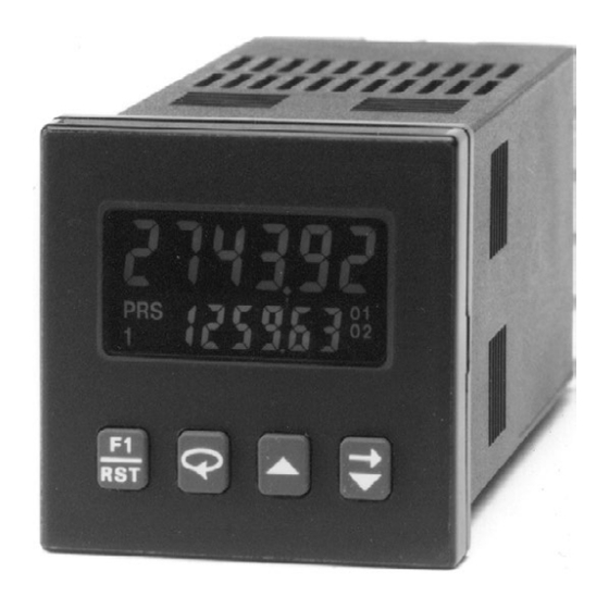
Red Lion Controls C48CS103
Single Preset Counter with Backlit LCD
A l l t r a d e m a r k s , b r a n d n a m e s , a n d b r a n d s a p p e a r i n g h e r e i n a r e t h e p r o p e r t y o f t h e i r r e s p e c t i v e o w n e r s .
• C r i t i c a l a n d e x p e d i t e d s e r v i c e s
• I n s t o c k / R e a d y - t o - s h i p
Artisan Scientific Corporation dba Artisan Technology Group is not an affiliate, representative, or authorized distributor for any manufacturer listed herein.
In Stock
Used and in Excellent Condition
Open Web Page
https://www.artisantg.com/91936-1
• We b u y y o u r e x c e s s , u n d e r u t i l i z e d , a n d i d l e e q u i p me n t
• F u l l - s e r v i c e , i n d e p e n d e n t r e p a i r c e n t e r
Advertisement
Table of Contents
Troubleshooting

Related Manuals for red lion C48CS103


Summary of Contents for red lion C48CS103
- Page 1 Red Lion Controls C48CS103 Single Preset Counter with Backlit LCD In Stock Used and in Excellent Condition Open Web Page https://www.artisantg.com/91936-1 A l l t r a d e m a r k s , b r a n d n a m e s , a n d b r a n d s a p p e a r i n g h e r e i n a r e t h e p r o p e r t y o f t h e i r r e s p e c t i v e o w n e r s .
- Page 2 THE 1/16 DIN COUNTERS MODEL C48C INSTRUCTION MANUAL...
- Page 3 Red Lion Controls the leader in today’s industrial market. Red Lion Controls has a complete line of industrial indication and control equipment, and we look forward to servicing you now and in the future.
-
Page 4: Table Of Contents
TABLE OF CONTENTS GENERAL DESCRIPTION ................................1 Safety Summary ..................................1 Block Diagram ..................................2 INSTALLATION & CONNECTIONS .............................. 3 Multiple Unit Stacking ................................3 Mounting Instructions ................................4 Unit Removal Procedure ................................4 Removing Unit Assembly ................................ 4 Installing Unit Assembly ................................5 Output Board .................................. - Page 5 TABLE OF CONTENTS (Cont’d) Auto Scrolling .................................. 15 Saving Program ................................15 USER INTERFACE/PROGRAMMING MODES ........................... 16 Programming Menu ................................16 Numeric Value entry method ............................16 Access Prescaler Value ..............................16 Prescaler (0.00001 - 9.99999*) ............................16 Decimal Point Position ..............................17 Count Input Mode ................................
- Page 6 TABLE OF CONTENTS (Cont’d) Serial Baud Rate and Parity Settings ..........................26 Serial Unit Address (00-99) ............................. 26 Serial Abbreviate Mnemonics ............................26 Print Options ..................................27 Print and Reset Count ..............................27 Prescaler Output Pulse at [Prescaler Output Model Only] ..................... 27 Prescaler Output Pulse Length (1-9) [Prescaler Output Model Only] ................
-
Page 8: General Description
GENERAL DESCRIPTION unauthorized changes to data values and unit configuration. The Standard Counter with dual presets is available with solid-state or relay The Model C48 Counter is available as a Standard Counter or a Batch outputs. The single preset model has a solid-state and relay output. The Batch Counter. -
Page 9: Block Diagram
BLOCK DIAGRAM A(+) B(-) RS-485 USER INPUT OPTION PLUG JUMPER RS-485 TX/RX CIRCUITRY SNK SRC USER 2 LED BACKLIGHT (TRANSMISSIVE NONVOLATILE USER INPUT POWER-UP/DOWN VERSION ONLY) FRAM MEMORY CIRCUITRY SENSE CIRCUITRY USER INPUT 1 LCD DISPLAY INPUT A INPUT A KEYPAD CIRCUITRY COMM. -
Page 10: Installation & Connections
INSTALLATION & CONNECTIONS The C48 Counter meets NEMA 4X/IP65 requirements for indoor use to provide a watertight seal in steel panels with a minimum thickness of 0.09 inch, or aluminum panels with a minimum thickness of 0.12 inch. 1.96 (49.8) The units are intended to be installed into an enclosed panel. -
Page 11: Mounting Instructions
Mounting Instructions PANEL 1. Prepare the panel cutout to the dimensions shown in Figure 3, Multiple Unit Stacking. CASE 2. Remove the panel latch from the unit. Discard the cardboard sleeve. 3. Carefully remove the center section of the panel gasket and discard. Slide the panel gasket over the unit from the rear, seating it against the lip at the front of the case. -
Page 12: Installing Unit Assembly
Output Board The C48C is supplied with an output board installed. The output board is preconfigured for the type of output needed, based upon the Model ordered. See Ordering Information, page 48, for available models. All relay output boards are field replaceable. -
Page 13: Emc Installation Guidelines
One of the most effective ways is to installation. Listed are some EMI guidelines for a successful installation in an place a diode across the inductive load. Most Red Lion products with solid industrial environment. -
Page 14: Power Wiring
POWER WIRING DC Versions (C48CXX1X) DC power (18 to 36 VDC) or low voltage AC power (24 VAC) is connected AC Versions (C48CXX0X) to terminals 11 and 12, labeled DC+ (AC) and DC- (AC) respectively. AC Power Wiring Primary AC power is connected to terminals 11 and 12, labeled AC. To Output Power reduce the chance of noise spikes entering the AC line and affecting the counter, For DC/ Low Voltage AC units that do not have PNP current sourcing... -
Page 15: Serial Communication Wiring
Serial Communications Wiring OUTPUT WIRING Relay Connections It is recommended that shielded (screened) cable be used for serial communications. This unit meets the EMC specifications using Alpha #2404 To prolong contact life and suppress electrical noise interference due to the cable or equivalent. - Page 16 SW3 - HI BIAS: Sets input trigger levels at mid-range, to accept outputs from INPUT B 2-wire proximity sensors, resistive photo-cells, and logic pulses SW4 - Same as SW1 with full 0 to +12V swings. SW5 - Same as SW2 Input trigger levels: V = 5.5 V max;...
-
Page 17: Various Sensor Output Connections
Various Sensor Output Connections NOTES: COUNT SWITCH OR ISOLATED TRANSISTOR OUTPUTS OLDER STYLE SENSORS WITH E-F OUTPUT - CURRENT CURRENT SOURCE CONNECTED (COUNT ON OPENING) SOURCE CONNECTED (COUNT ON FALLING EDGE) SENSOR VOLTAGE AND CURRENT SENSOR The DC OUT/IN terminal can supply +12 USER INPUT 1 USER INPUT 1 VDC @ 100 mA max. -
Page 18: Front Panel Description
FRONT PANEL DESCRIPTION The front panel bezel material is flame and scratch resistant, textured plastic MAIN DISPLAY with clear viewing window that meets NEMA 4X/IP65 requirements, when Displays count value. properly installed. Continuous exposure to direct sunlight might accelerate the Also displays mnemonic of aging process of the plastic material used in the bezel. -
Page 19: Basic Operation
BASIC OPERATION Normal Operating Mode In the normal operating mode, the count or batch/total value is shown on the Single and Dual Preset Units main display. By successively pressing the key, the accessible presets, The C48CS and C48CD have one counter that keeps track of the input pulse prescaler, output time values, or batch/total count can be viewed in the count. -
Page 20: Protected Value Menu
Protected Value Menu Preset Change MAIN DISPLAY LOOP Mode The Protected Value Menu allows access to selected presets, prescaler, and output time values without having them viewable keys are used to change value. Press or changeable from the main display. To enter the protected to enter value. -
Page 21: Front Panel Accessible Functions With Program Disable
Front Panel Accessible Functions With Program Disable There are several ways to limit the programming of parameters from the front may need to be entered, depending on the Program Disable Setting. Front Panel panel keypad. The Accessible Value parameters are used with the Program Function Key F1 cannot be selected for program disable. -
Page 22: Programming General Description
PROGRAMMING GENERAL DESCRIPTION Digit Entry Programming of the C48 Counter is done through the front panel keypad. English language prompts, flashing parameter values, and the front panel If the data entry method has been set to “digit entry”, the least significant keypad aid the operator during programming. -
Page 23: User Interface/Programming Modes
USER INTERFACE/PROGRAMMING MODES Access Prescaler Value The operating modes of the C48 Counter are programmed using the front panel keypad. Accessibility to the Programming Menu depends on the Program This parameter configures the type of access given to the ... -
Page 24: Decimal Point Position
Decimal Point Position Count Modes Programmable for display of 0 to 5 digits right of Input A signal is used for the count input. Input B is used in combination with decimal point. Input A for Count Direction Control, Quadrature counting, Anti-coincidence Add/Subtract, or Anti-coincidence Add/Add counting applications. -
Page 25: Counter (1) Operating Mode
QUAD 1 - Quadrature counting modes are primarily used in positioning and Reset Type: Batch Model anti-jitter applications. This mode works due to the manner in which the two Auto - unit automatically resets when count triggers incoming pulses are positioned relative to each other. The pulse signal on main preset’s output or at its timed output end, as Input B is shifted 90°... - Page 26 SINGLE PRESET OPERATING MODES DUAL PRESET/ BATCH COUNTER 1 OPERATING MODES Use either of the two charts below for more information on specific operating Use either of the two charts below for more information on specific modes. operating modes. SINGLE PRESET OPERATING MODES DUAL PRESET AND BATCH COUNTER 1 OPERATING MODES Manual Reset to Zero, Latched Output - Manual Reset to Zero, Latched Outputs...
-
Page 27: Counter 2 Assignment (Batch Model Only)
Counter 2 Assignment (Batch Model only) DUAL PRESET/ BATCH COUNTER 1 OPERATING MODES This parameter configures Counter 2 to function as a MODE# RESET TYPE RESET OUTPUT 1 OUTPUT 2 Batch or Total Counter. √ √ √ √... -
Page 28: Counter 2 Operating Mode (Batch Model Only)
Counter 2 Operating Mode (Batch Model only) The chart below shows operating modes for Counter 2 of the Batch Counter Model. Reset Type: Auto - unit automatically resets when count reaches RESET TYPE RESET OUTPUT 3 MODE Output 3 or timed output 3 end. -
Page 29: Access Preset Values
Access Preset Values Single Preset Preset Values (0-999999) Model This parameter configures the type of access given to The Preset Values control the activation of the respective each Preset Value when in normal operating mode with Outputs. Programming disabled. The accessibility of each Preset can ... -
Page 30: Access Output Time Values
Access Output Time Values Output 1 Time Value This parameter configures the type of access given to The Output 1 Time Value controls the Output 1 duration, each Output Time Value when in normal operating mode ... -
Page 31: Reverse Annunciator Logic
User Inputs Programming Keys: - Selects Output being configured as indicated by the Up to three external User Inputs plus the front panel function key are number on the left side of the bottom display line. available on the C48 Counter/Batch Counter. The parameter list below shows ... -
Page 32: User Input 1
User Input 2 MODE DESCRIPTION User Input 2 can be programmed for any of the Reset Counter 2 (Edge Triggered) [Batch model Only]; When the user input is activated, the Counter 2 value and outputs will be momentarily parameters listed previously except for the Inhibit function. -
Page 33: Scroll Display
Scroll Display Serial Unit Address (00-99) This parameter determines whether or not the secondary This parameter configures the Serial Unit Address. The display will scroll or sequence automatically to the next Address is used to uniquely identify each unit when available value. -
Page 34: Print Options
Print Options Print and Reset Count The Print Options parameter determines which values This parameter is used in conjunction with Print Request are printed in response to a Print Request command or user (User Input or Serial Command) and the Print Options to input print request. -
Page 35: Factory Settings
Factory Settings OUTPUTS This parameter is used to reset all parameters to their ACCESS OUTPUT TIME VALUES factory defaults. The Factory Settings Chart below shows OUTPUT RESOLUTION the settings for each programming parameter. OUTPUT 1 TIME ... -
Page 36: User Settings Chart
* Settings on the previous page are shown for Dual Preset and Batch models. Changes to Factory Settings for Single Preset Model are as follows: OUTPUTS COUNTER OPERATING MODE ACCESS OUTPUT TIME VALUES PRESET 1 VALUE OUTPUT RESOLUTION ... -
Page 37: Rs-485 Serial Communications
RS-485 SERIAL COMMUNICATIONS DATA FORMAT - 10 BIT FRAME (Parity = none) RS-485 communications allows for transmitting and receiving of data over a single pair of wires. This feature can be used for monitoring various values, changing values, and resetting output(s), from a remote location. Typical 8 DATA BITS devices that are connected to a C48C unit are a printer, a terminal, a PLC, an HMI, or a host computer. - Page 38 In a multiple unit configuration, an asterisk (2AH) must be sent to clear the VALUE IDENTIFIERS MNEMONIC input buffer of all units on the line after a transmit value or print request A (41H) Preset 1 command is sent to a specific unit on the line. The C48C will require a B (42H) Preset 2 maximum of 50 msec to process the asterisk (*).
-
Page 39: Receiving Data
It is recommended that a “Transmit Value” command follow a “Change The first two digits transmitted are the unit address followed by one blank Value” Command. If this is done, the reception of the data can provide a timing space. The next three characters are the mnemonics followed by three or more reference for sending another command and will ensure that the change has blank spaces. -
Page 40: Serial Connections
Serial Connections Troubleshooting Serial Communications When wiring, refer to the numbers listed on the label with the terminal If problems are encountered when interfacing the C48C(s) and host device or description for installing each wire in its proper location. printer, the following check list can be used to help find a solution. For RS-485, the data (transceiver) wires connect to the A(+) and B(-) 1. -
Page 41: Connecting To A Host Terminal
OFFICE PC CONNECTING TO A HOST TERMINAL (WITH RS485 INTERFACE CARD INSTALLED) Six C48C units are used to monitor and control parts C48C is programmed for a different address and all are programmed for the same baud rate and parity as the packaging machines in a plant. -
Page 42: Prescaler Output Option
PRESCALER OUTPUT OPTION PRESCALER OUTPUT LENGTH The prescaler output is useful for providing a lower frequency scaled pulse PRESCALER OUTPUT LENGTH VALUE VALUE VALUE VALUE train to a PLC or another external totalizing counter. The prescaler output ... -
Page 43: Appendix "A" - Application Example
APPENDIX “A” - APPLICATION EXAMPLE Slow Down & Cut to Length with Total Yardage To improve production efficiency, a wallpaper manufacturing plant is Circumference of pinch roller: installing cut to length counters on the roll form machines. Currently, electro- circumference = π x diameter mechanical counters are used for length measurements. -
Page 44: Application Programming
APPLICATION PROGRAMMING (locked) PRS1 (value 0.25 less than PRS2 for slow down) PRS2 ... -
Page 45: Appendix "B" - Specifications And Dimensions
APPENDIX “B” - SPECIFICATIONS AND DIMENSIONS 1. DISPLAY: 2 Line by 6 digit LCD display. Positive image reflective or PEAK (START-UP CURRENT): AC or DC Power: 500 mA peak start-up current for 10 msec max. negative image transmissive with red (top line) and green (bottom line) backlighting 3. - Page 46 7. MAX. COUNT RATE: Model dependent. All listed values are in KHz. Batch Model C48CB: With Counter 2 configured as a Batch Counter ( Single Preset Model C48CS QUAD QUAD PRESCALER C1-Usr C2-Usr PRESCALER C1-Usr C2-Usr Ad-Sub Ad-Sub VALUE C1-Ud...
-
Page 47: Certifications And Compliances
8. OUTPUTS: (Output type and quantity, model dependent) 10. CERTIFICATIONS AND COMPLIANCES: Solid-State: CE Approved NPN Open Collector: I = 100 mA max. @ V = 1.1 VDC max.; EN 61326-1 Immunity to Industrial Locations = 30 VDC max. Emission CISPR 11 Class A PNP Open Collector: I = 100 mA max.(See note);... -
Page 48: Appendix "C" - Troubleshooting
APPENDIX “C” - TROUBLESHOOTING The majority of problems can be traced to improper connections or incorrect set-up parameters. Be sure all connections are clean and tight, that the correct output board is fitted, and that the set-up parameters are correct. Also, be sure the DIP switch settings and the User Input Plug Jumper position are correct for the particular application. - Page 49 APPENDIX “C” - TROUBLESHOOTING (Cont’d) POSSIBLE CAUSE REMEDIES PROBLEMS CAN NOT ENTER INTO 1. Front panel disabled. 1. Check “Front Panel Accessible Functions With Program PROGRAMMING Disable” section of the manual. PROCESS, BATCH, OR 1. User input not properly programmed. 1.
-
Page 50: Appendix "D" - Calculating The Prescaler
APPENDIX “D” - CALCULATING THE PRESCALER The C48C is factory set to provide one count on the display for each pulse For the preceding example, the prescaler is calculated by plugging 2 and 48 that is input to the unit. In many applications, there will not be a one to one into the formula: correspondence between input pulses and desired display units. -
Page 51: Appendix "E" - Terminal Configurations For C48 Counters
APPENDIX “E” - TERMINAL CONFIGURATIONS FOR C48 COUNTERS C48CXX0X VERSIONS (85 to 250 VAC POWERED) CAUTION: Observe proper polarity when connecting DC voltages. Damage to the unit will occur if polarity is reversed. C48CS - SINGLE PRESET RELAY AND C48CD - DUAL PRESET RELAY OUTPUTS C48CD - DUAL PRESET SOLID-STATE OUTPUTS SOLID-STATE OUTPUTS RS-485 OPTION... - Page 52 TERMINAL CONFIGURATIONS FOR C48 COUNTERS (Cont’d) C48CXX1X VERSIONS (18 to 36 VDC/24 VAC POWERED) CAUTION: Observe proper polarity when connecting DC voltages. Damage to the unit will occur if polarity is reversed. C48CS - SINGLE PRESET RELAY AND C48CD - DUAL PRESET RELAY OUTPUTS C48CD - DUAL PRESET SOLID-STATE OUTPUTS SOLID-STATE OUTPUTS RS-485 OPTION...
-
Page 53: Appendix "F" - Ordering Information
18-36 VDC/24 VAC 85 to 250 VAC 1 Preset Counter, Reflective LCD C48CS013 C48CS003 RBC48001 C48CS 1 Preset Counter, Backlit LCD C48CS113 C48CS103 RBC48001 2 Preset Counter, Reflective LCD C48CD015 C48CD005 2 Preset Counter, Reflective LCD C48CD012 C48CD002 RBC48003 2 Preset Counter, Reflective LCD... - Page 54 THREE PRESET BATCH COUNTERS PART NUMBERS FOR AVAILABLE REPLACEMENT RELAY NPN O.C. SUPPLY VOLTAGES MODEL NO. DESCRIPTION RS485 RELAY OUTPUT OUTPUT(S) OUTPUT(S) BOARD 18-36 VDC/24 VAC 85 to 250 VAC 3 Preset Batch Counter, Reflective LCD Yes (O1) C48CB003 RBC48004 3 Preset Batch Counter, Reflective LCD Yes (O1) C48CB008...
-
Page 55: Limited Warranty
LIMITED WARRANTY (a) Red Lion Controls Inc., Sixnet Inc., N-Tron Corporation, or Blue Tree Wireless Data, Inc. (the “Company”) warrants that all Products shall be free from defects in material and workmanship under normal use for the period of time provided in “Statement of Warranty Periods” (available at www.redlion.net) current at the time of shipment of the Products (the “Warranty Period”). - Page 56 C48C/IM - G 01/17 DRAWING NO. LP0354...
Need help?
Do you have a question about the C48CS103 and is the answer not in the manual?
Questions and answers