
Related Manuals for Matsusada Precision P4KF-80 Series


Summary of Contents for Matsusada Precision P4KF-80 Series
- Page 1 Instruction Manual P4KF-80 Series Model: *281.9.006* B/N: 281.9.006 Rev. 0.0 F-RA-001-2R3...
-
Page 2: Product Warranty
Notes This publication may not be copied, reproduced, or reprinted, in full or in part, without permission. The content of this document is subject to change without notification. Thank you for your understanding. Although every effort has been made to ensure the accuracy of the content of this manual, please contact our sales office if you find any errors. -
Page 3: Using This Product Safely
Matsusada Precision shall not be liable for any damage that occurs due to failure to observe the warnings, cautions, and procedures described in this manual. -
Page 4: Connecting The Power Cable
Doing so could result in electric shock or fire. ◆ Input voltage Check the input terminal on the product, and refer to the page in this manual that describes the input voltage. Do not supply a voltage that is outside the range provided in the specifications. P4KF-80 Series... -
Page 5: Operating Temperature And Humidity
Use a short-circuit grounding device to discharge the terminal by connecting it to ground, and then use a voltmeter to confirm that no voltage remains. This includes not only the input/output terminals, but also all terminals for communications and remote control. P4KF-80 Series... -
Page 6: Replacing Fans
To ensure a longer product life, the fans should be replaced periodically. Please contact our sales office for more information about replacing fans. (An additional fee will be charged when replacing fans. Do not attempt to replace a fan yourself, because there is a risk of electric shock.) P4KF-80 Series... -
Page 7: Table Of Contents
Constant Current Mode (CC mode) ....................19 4-1-3 Crossover Operation ......................... 19 Turning the Power On ..........................20 4-2-1 Setting the Switch to POWER ON ....................20 4-2-2 Setting the Switch to POWER OFF ....................20 OUTPUT Switch ............................21 P4KF-80 Series... -
Page 8: Contents
Turning Output ON/OFF ........................... 58 Analog Remote Control ..........................59 9-3-1 Setting the Output Voltage Program Based on External Voltage (Input Voltage: 0 to 10 V DC) ..59 9-3-2 Setting the Output Voltage Program Based on External Resistance ..........60 P4KF-80 Series... - Page 9 Characters Used for Commands ..................... 64 10-5-5 Matsusada Precision Original Command List ................. 65 10-5-6 Descriptions of Matsusada Precision Commands (Common to All P4KF-80 Series Models) ..66 10-5-7 Matsusada Precision Commands (For the -LDe Option) ..............69 10-5-8 Matsusada Precision Commands (For the -LIc Option) ..............71 10-6 SCPI Command Program ........................
- Page 10 12 Options ................................96 12-1 RS-232C Interface (-LGmb Option) ....................... 96 12-2 Optical Interface (-LGob Option) ......................97 13 Troubleshooting............................. 98 13-1 Troubleshooting when Using Digital Control ..................98 13-2 Inquiries ..............................98 14 When a Malfunction Occurs .......................... 99 viii P4KF-80 Series...
-
Page 11: Features And Specifications
Overview Products in the P4KF-80 series output a wide range of voltage/current within the rated output power, and can output a wide range of voltage and current not possible with conventional products. They can output a wide range of voltage and current required for testing various devices such as rechargeable batteries and semiconductors, and for the power supplies for communication equipment, etc., in a highly stable and... -
Page 12: Product Specifications
Ripple noise (RMS value) *9 mArms Ambient temperature vs. output ppm/°C variation Protection function Overvoltage protection operation ±0.1% of reading ± 5 digits accuracy Overcurrent protection operation ±0.2% of reading ± 5 digits accuracy OTP operating temperature °C P4KF-80 Series... - Page 13 *9 The voltage ripple (RMS value) at the maximum voltage output that can be output at the rated output current, divided by the value of the load *10 1% to 100% of rated voltage with local or digital remote *11 1% to 100% of rated current with local or digital remote P4KF-80 Series...
-
Page 14: Before Using This Product
After unpacking and before wiring, inspect the product for any abnormalities. Check the front panel, rear panel, top surface, and chassis for scratches, dents, or other evidence of impact from shipping or handling. If you find any abnormalities, please contact the carrier and Matsusada Precision. Precautions for Handling the Product Warning ... -
Page 15: Installation
(Pay particular attention to the bottom surface of the power supply.) If you are unable to ensure the space indicated above, use our rack mount holders and provide forced air cooling with a fan. P4KF-80 Series... -
Page 16: Bias
Since a bias voltage is generated at the output terminals, be careful to avoid Caution electric shock. 2-4-4 Usage Conditions This product is designed to be used under the conditions listed in the table below. P4KF-80 Series Model P4KF-80L P4KF-80N P4KF-80M P4KF-80H... -
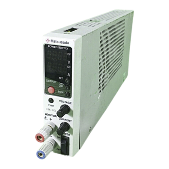
Page 17: External Appearance
Output current setting knob Front monitor terminal (+) Front monitor terminal (-) POWER ON/OFF switch 2-5-2 Rear Panel (Standard Interface) Output terminal Sense terminal (TB2) LAN port USB port (Type B) Analog remote terminal (TB1) AC input inlet P4KF-80 Series... -
Page 18: External Dimensions
2 Before Using This Product 2-5-3 External Dimensions Units: [mm] P4KF-80 Series... -
Page 19: Connections
AC Input Connection The rated input voltage for the P4KF-80 series is single-phase 100 Vac to 240 Vac. See "2-4-4 Usage Conditions" for more information about the input voltage range and the input current. -
Page 20: Connection To Output Terminal
7 mm Tightening torque 0.5 to 0.6 N・m Warning Use only stripped wires. Do not solder the section of copper wire that is covered, because it will not be possible to connect the wire securely. Output terminal connector P4KF-80 Series... - Page 21 When a large-capacity capacitor is connected as a load, even if the current sink function is turned on, the charge cannot be completely removed. Therefore, voltage might remain at the output terminals, which is dangerous. Always check for residual voltage before touching the outputs or loads. P4KF-80 Series...
-
Page 22: Connection To Front Monitor Terminal
3 Making Connections 3-2-2 Connection to Front Monitor Terminal The specifications for the P4KF-80 series are for output from the rear panel output terminal. For output from the front monitor terminal, these specifications might not be satisfied. Caution Warning Hazardous voltages are generated at the front monitor terminal and at the load. To prevent electric shock, make sure that the load and connection areas cannot be touched. - Page 23 3 Making Connections Fit the safety plug cover (red and blue components) onto the end of the banana plug. Connect it to the front monitor terminal. P4KF-80 Series...
-
Page 24: Remote Sensing
If you are using a shielded wire, the shield should be connected to only "-" on the product side or the load side. If the "+" and "-" of the cable for remote sensing are connected in reverse, or if the Caution guaranteed sensing voltage is exceeded, the unit will not operate properly. P4KF-80 Series... - Page 25 If remote sensing is not used, "+", "+S", "-", and "-S " on the sense connector should be short-circuited, and the connector should be installed on TB2. If the product is used without Caution making this connection, a malfunction might occur. P4KF-80 Series...
-
Page 26: Parallel Connections
- + -Vout Connecting Inductive Loads For inductive loads, insert a diode with a rating greater than the output voltage and output current of the product, to protect the product from load kickback. Inductive load (Transformer, motor, etc.) P4KF-80 Series... -
Page 27: Connecting Loads With Continuous Ripples
Forward current capacity 3 to 10 times the rated output current of the product Low amount of loss Consider the heat generated by the protection diode. If heat dissipation is insufficient, the connected protection diode will burn out. Cannot be used simultaneously with remote sensing. P4KF-80 Series... -
Page 28: Installing The Front Ground Terminal
3-10 Installing the Front Ground Terminal With the P4KF-80 series, a ground terminal can be connected to the front of the unit. Use the front ground terminal bracket and M4 screws that are included. 1. Remove the two rubber feet that are 2. -
Page 29: Basic Functions And Operations
If the load fluctuates while the product is in constant current mode and the load voltage becomes larger than the value that has been set for the voltage, the product automatically shifts from constant current mode to constant voltage mode. P4KF-80 Series... -
Page 30: Turning The Power On
Voltage might remain at the output. When touching the input/output terminals, connectors, and any wiring or load Warning connected to the input/output terminals, use a voltmeter to confirm that no voltage remains at the output. P4KF-80 Series... -
Page 31: Output Switch
Output current setting (Current setting knob) When remote control is being used, you cannot use the output setting knobs to Caution change the settings. Either enter the values by remote control or switch to local mode to set them. P4KF-80 Series... -
Page 32: Fine Function
To set the selected digit in the output voltage or output current, turn the output voltage setting knob or output current setting knob. Note that when the OUTPUT ON/OFF switch is ON (when the OUTPUT LED is on), both voltage and current are output. Digit to be changed is displayed brightly. Press the knob P4KF-80 Series... -
Page 33: Ovp (Overvoltage Protection)/Ocp (Overcurrent Protection)
ON or set the LS (remote switch) to ON. ACF (AC Input Failure) If the input voltage drops or the input voltage becomes unstable and the power supply does not operate normally, ACF is activated and the output is stopped. P4KF-80 Series... -
Page 34: Key Lock Function
2 seconds 10 seconds How to release Press and hold the LOCK switch for Press and hold the LOCK switch for about the lock about 2 seconds 2 seconds Not available when the multi-set function Notes is enabled P4KF-80 Series... -
Page 35: Output Auto-Restore Prevention Function
4-12 Fault Display List Display Item OVP/E01 Overvoltage protection OtP/E02 Overcurrent protection Sr/E03 Overpower protection OCP/E05 Over-temperature protection ACF/E07 AC input voltage drop P4KF-80 Series... -
Page 36: Application Functions
Preset "b" Preset "c" The mode display shows "a", "b", and "c" only when the SET, OVP/OCP, or LOCK switch is pressed. You can also confirm the current memory based on the interval at which the SET LED flashes. P4KF-80 Series... - Page 37 The SET LED stops flashing and multi-set mode ends. *When the POWER ON/OFF switch is set to ON, the multi-set function returns to the state it was in when the power was cut off. Press and hold the output preset switch P4KF-80 Series...
-
Page 38: Master/Slave Function (Only When The -Lgmb Or -Lgob Option Is Selected)
Master/Slave Function (Only when the -LGmb or -LGob Option is Selected) For master/slave operation with a digital interface, when multiple P4KF-80 series units are controlled with a single unit set as the master machine, the slave machines connected to the master machine are set to the same output voltage/current/OVP/OCP/OUTPUT status as the master machine. -
Page 39: Master/Slave Function Settings
To output again from a slave machine whose output has been shut down, turn the OUTPUT switch OFF on the master machine, reset everything, and then start output again. The above operation is performed for OVP, OCP, OTP, sense reverse connection, and ACF. P4KF-80 Series... -
Page 40: Master/Slave Connections
5 Application Functions 5-2-2 Master/Slave Connections P4KF-80 Series, Rear Panel GP-M cable *GP-optical cable when using the -LGob option P4KF-80 Series, Rear Panel Max. 16 units can be connected (Max. 32 units with the -LGob option) P4KF-80 Series... -
Page 41: Delay Trigger Function
OFF delay time (1.0 s). the OFF delay setting. Configure the settings as shown above, and then exit the startup menu. If OUTPUT is set to OFF during output, a 1.0-second countdown starts. When the countdown reaches 0, output stops. P4KF-80 Series... -
Page 42: Canceling A Delay Trigger
OFF or set the POWER ON/OFF switch to OFF while the count is displayed. This will cancel the countdown. Note that if the OUTPUT ON/OFF switch is pressed during the countdown, the unit will Caution return to the state it was in before the switch was pressed. P4KF-80 Series... -
Page 43: Pulse Ramp Sequence Function (-Lde Option)
Take this accuracy into consideration when using this function for long periods of time. Press Press OUTPUT OUTPUT Pulse sequence starts Pulse sequence stops When OFF When ON 1 cycle The sequence stops after the specified number of times, or when OUTPUT is pressed. P4KF-80 Series... -
Page 44: Example Of Pulse Sequence Settings
Set the OFF time to 1 second. Press the OVP/OCP setting switch Current setting knob Press If the number of repetitions is set to 0, ON/OFF is OUTPUT 1.0 sec 2.0 sec repeated until OUTPUT is pressed. 1 cycle P4KF-80 Series... - Page 45 Set the OFF time to 1 second. Press the OVP/OCP setting switch Current setting knob Press Pulse sequence OUTPUT 1.0 sec 2.0 sec stops For 2 repetitions, the sequence turns ON/OFF twice and then stops automatically. 1 cycle P4KF-80 Series...
- Page 46 ON time settings for "b" and "c". Set the ON time for each to 1 second. To next page Voltage setting knob Current setting knob P4KF-80 Series...
- Page 47 1.0 sec 2.0 sec 3.0 sec 4.0 sec stops 3.0 V 2.0 V 1.0 V 1 cycle For 2 repetitions, the sequence turns ON/OFF twice and then stops automatically. *Output occurs at the ON time for each memory. P4KF-80 Series...
-
Page 48: Ramp Function
If only multi-set and the ramp function are used together, the ramp function can be Caution used only for turning OUTPUT on/off. Note that the ramp function does not operate when switching memories. OUTPUT OUTPUT OUTPUT LED pressed ON ramp operation starts OFF ramp operation starts ON ramp time OFF ramp time P4KF-80 Series... -
Page 49: Example Of Using The Ramp Function
Current setting knob Press and hold the key lock setting switch to register the ramp operation. Press the key lock setting switch OUTPUT OUTPUT OUTPUT LED 1.0 sec pressed 1.0 sec Ramp operation Ramp operation when ON when OFF P4KF-80 Series... - Page 50 Stops when OUTPUT OUTPUT 1.0 sec 2.0 sec 3.0 sec 4.0 sec 5.0 sec 6.0 sec 7.0 sec 8.0 sec is pressed When ON When OFF Ramp Ramp operation operation when ON when OFF 1 cycle P4KF-80 Series...
- Page 51 Press the key lock setting switch memory to 1 second. Press the preset setting switch Current setting knob Voltage setting knob Press and hold the key lock setting switch to Current setting register the ramp knob operation. Press the key lock setting switch P4KF-80 Series...
- Page 52 Output 0 Roff 1 cycle Memory a output ramp time Memory a output time Memory b output ramp time Memory b output time Memory c output ramp time Memory c output time Roff OFF ramp time Toff When OFF P4KF-80 Series...
-
Page 53: Output Current Totalization Function (-Lic Option)
"Accumulated total current value until power off" each time the output preset switch is pressed. To switch back to the "Voltage/current display", press the output preset switch several times to change the display. Present total Previous total Voltage/current Accumulated total current value current value settings current value Voltage/current Switches automatically Current time P4KF-80 Series... -
Page 54: Present Total Current Value
"b" (for before) is shown as the leftmost digit on the ammeter. Integer for previous total current value "b" is displayed to indicate Decimal places for previous total the previous total. current value P4KF-80 Series... -
Page 55: Accumulated Total Current Value
"Total current setting/total current value setting", and "Units of display setting for total current value" each time the OVP/OCP setting switch is pressed. Units of display Total current Time setting setting for total setting/total current value/time current value value setting OVP/OCP settings setting Voltage/curren P4KF-80 Series... -
Page 56: Settings By Time
To reset this setting, either disable the Hold setting or turn off the power. Total current setting value VOLTAGE Total current setting (Voltage setting knob) CURRENT Total current setting Total current Total current Total current value setting OFF setting ON setting Hold (Current setting knob) P4KF-80 Series... -
Page 57: Units Of Display Setting For Total Current
AS (As). CURRENT Units of display setting for total current value (Current setting knob) Units of display for Units of display for Units of display for total current value As total current value Am total current value Ah P4KF-80 Series... -
Page 58: Startup Menu
To exit (register) the startup menu, press and hold the key lock setting switch from the menu to be registered. Press and hold the key lock setting switch Caution FACt rSt (factory reset) is displayed, all settings are reset to their default settings. P4KF-80 Series... -
Page 59: Startup Menu List
Sets the delimiter to be used in communication Delimiter settings commands *1 With -LDe option only *2 With -LIc option only *3 With standard interface only *4 With -LGmb/-LGob options only *5 With -LGob option only P4KF-80 Series... -
Page 60: Description Of Menus
Sets the fail-safe function to ON (enabled)/OFF (disabled). Use the current setting knob to configure this setting. For more information about this function, see "9-4 Remote Programming in Fail-Safe Mode". The default setting (or factory reset) is OFF. Fail-safe function Fail-safe function enabled disabled P4KF-80 Series... - Page 61 Specify the target for analog remote programming. Use the current setting knob to change this setting. Analog remote Analog remote voltage Analog remote current Analog remote programming disabled programming enabled programming enabled Voltage programming enabled Current programming enabled P4KF-80 Series...
- Page 62 OVP/OCP setting switch (press) Configure the OFF time setting. Use the current setting knob to change this setting. You can set a value from 0.0 s to 59.9 s, from 0 to 59 minutes, or from 0 to 9999 hours. P4KF-80 Series...
- Page 63 Hours Minutes (m) Seconds (s) Key lock setting switch (press) Set the target for the ramp operation. Use the current setting knob to change this setting. Both voltage and Voltage only Current only current P4KF-80 Series...
- Page 64 Configure the communication speed settings for the RS-232C interface and the optical interface. You can set 9600 bps, 19200 bps, or 38400 bps. Use the current setting knob to change this setting. The default setting (or factory reset) is 9600 bps. 9600 bps setting 19200 bps setting 38400 bps setting P4KF-80 Series...
- Page 65 Press and hold the output preset switch Turn the voltage setting knob IP address Subnet mask Default gateway MAC address OVP/OCP setting switch (press) Sets DHCP to ON (enabled)/OFF (disabled). Use the current setting knob to configure this setting. DHCP enabled DHCP disabled P4KF-80 Series...
- Page 66 Set the delimiter to be used in communication commands. You can set CR, LF, or CRLF. Use the current setting knob to change this setting. The default setting (or factory reset) is CR. Delimiter settings Delimiter settings Delimiter settings "LF" "CR" "CRLF" P4KF-80 Series...
-
Page 67: Analog Remote Operation
Keep wiring from pins short (no more than a few meters). Do not connect PIN1, PIN3, or PIN5 of Do not connect this product in series or share TB1 to a "-" output. a common control voltage. Load × Prohibited × Load × P4KF-80 Series... -
Page 68: Turning Output On/Off
Internal circuitry Connections made by the customer 470 Ω TTL signal External relay + 470 Ω - TTL LOW = OUTPUT ON TTL HIGH = OUTPUT OFF External relay SHORT = OUTPUT ON External relay OPEN = OUTPUT OFF P4KF-80 Series... -
Page 69: Analog Remote Control
Confirm that the mode for the output voltage setting is set to remote (external voltage). Set the output voltage based on the external voltage. Internal circuitry Connections made by the customer + 0 to 10 V DC Common P4KF-80 Series... -
Page 70: Setting The Output Voltage Program Based On External Resistance
Set the output current based on the external resistance. With a resistance value of 0 to 10 kΩ, the setting can be in the range from 0 to the rated current. Internal circuitry Connections - + made by the 1 mA customer 0 to 10 kΩ (Common) P4KF-80 Series... -
Page 71: Remote Programming In Fail-Safe Mode
1 mA customer 0 to 10 kΩ (Common) Note that the fail-safe function will not operate if either the voltage program or the current Caution program, or both, are set to be controlled by an external voltage. P4KF-80 Series... -
Page 72: 10 Digital Remote Operation
For the default IP address setting, the unit searches for DHCP when the product starts up. If a DHCP server is found, the IP address will be set automatically. If a DHCP server is not found within about 30 seconds, set the IP address manually. P4KF-80 Series... -
Page 73: Matsusada Precision Original Command Program
10 Digital Remote Operation 10-5 Matsusada Precision Original Command Program 10-5-1 Command Format Example: To set the output configured in Unit 1 to ON, enter the following command. ○○ (1) Delimiter (2) Parameter (3) Command (4) Unit No. (1) Enter a delimiter. -
Page 74: Command Response String
・ Letters of the alphabet used in commands are not case sensitive. ・ In the command string, use a space (20 ) as the "unit number", "command", and "parameter" delimiter. Table ASCII Codes Upper Lower ” & ‘ < ¥ > P4KF-80 Series... -
Page 75: Matsusada Precision Original Command List
10 Digital Remote Operation 10-5-5 Matsusada Precision Original Command List Table Matsusada Precision Original Command List (Common to All P4KF-80 Series Models) Category Command Function Voltage VSET Sets the output voltage value Output value Current ISET Sets the output current value... -
Page 76: Descriptions Of Matsusada Precision Commands (Common To All P4Kf-80 Series Models)
10 Digital Remote Operation 10-5-6 Descriptions of Matsusada Precision Commands (Common to All P4KF-80 Series Models) VSET command Sets the output voltage value. Range 0 to the rated voltage value Resolution See "10-9 Resolution of the Setting Values and Return Values for Commands". - Page 77 Query In response to "SC?", returns SC=OFF/SC=ON. HEAD command Sets whether a command header is added when an MTP command query is made. Range OFF/ON HEAD OFF Example format HEAD ON Query In response to "HEAD?", returns OFF/HEAD=ON. P4KF-80 Series...
- Page 78 ・ Either OFF/ON, LO/RM, or CC/CV is output. ・ The error status is returned for all errors that have occurred. Notes ・ A space (20 ) is output as a delimiter for each status. P4KF-80 Series...
-
Page 79: Matsusada Precision Commands (For The -Lde Option)
10 Digital Remote Operation 10-5-7 Matsusada Precision Commands (For the -LDe Option) VSSWP command Sets the voltage value attained during the sweep operation. Range 0 to the rated voltage value Resolution See "10-9 Resolution of the Setting Values and Return Values for Commands". - Page 80 ⇒ Maintains the current value after completing the sweep. SWPEI 1 Example format ⇒ Returns to the current value before the sweep started, after SWPEI 2 completing the sweep. Default setting Query In response to "SWPEI?", returns SWPEI=0/SWPEI=1/SWPEI=2. Notes "Multi-commands" are supported for this command. P4KF-80 Series...
-
Page 81: Matsusada Precision Commands (For The -Lic Option)
10 Digital Remote Operation 10-5-8 Matsusada Precision Commands (For the -LIc Option) IC command Sets OFF/ON for the output current totalization function. Range OFF/ON ⇒ Turns the output current totalization function OFF. IC OFF Example format ⇒ Turns the output current totalization function ON. - Page 82 0.0 s to 9999 h 59 m 59.9 s Format AHBTIM AHBTIM=1234h56m59.9s ⇒ (Previous operation time) = (1234 hours 56 minutes 59.9 seconds) ⇒ (Previous operation time) = (1 hour 2 minutes Return example AHBTIM=1h02m03.0s 3.0 seconds) ⇒ (Previous operation time) = (0.0 seconds) AHBTIM=0h00m00.0s P4KF-80 Series...
-
Page 83: Scpi Command Program
SOURce:VOLTage MAX;:OUTPut:STATe ON It is necessary to return to the root node if there is a different hierarchy, even if the path is the same for a portion of the hierarchy. Combined commands (Example 3) SOUR:VOLT:PROT MAX;:SOUR:VOLT:LIM MAX P4KF-80 Series... - Page 84 - If ALL is set in the INSTruments command, do not send query commands. If multiple units are connected, the commands might not be returned normally. - The total number of characters in combined commands should be no more than 128, including delimiters. P4KF-80 Series...
-
Page 85: Scpi Command List
10 Digital Remote Operation 10-7 SCPI Command List Table SCPI Command List (Common to All P4KF-80 Series Models) Command Function Units Acquires company name, model name, serial *IDN? No., version information *RST Resets parameters SYSTem? Acquires local/remote SYSTem:LOCal Sets local mode... - Page 86 Set n for each setting value, and set MAX/MIN for the maximum/minimum values. Set ON/1 to turn a value ON, and OFF/0 to turn a value OFF. * Capital letters are required. Lower case letters can be omitted. (Example: SYSTEM:LOCAL and SYST:LOC have the same meaning.) P4KF-80 Series...
-
Page 87: Scpi Commands
10 Digital Remote Operation 10-8 SCPI Commands 10-8-1 SCPI Commands (Common to All P4KF-80 Series Models) *IDN? Acquires company name, model name, serial No., version information. Format *IDN? Return Matsusada Precision,P4KF-80N,123456S,v1.0.0 example ([company name],[model name],[serial No.],[version information]) *RST Resets parameters. - Page 88 "V", "kV", "mV" Example format VOLT 12.34 Default setting Query In response to VOLT?, returns the voltage value that has been set. For more information about resolution, see "10-9 Resolution of the Setting Values and Notes Return Values for Commands". P4KF-80 Series...
- Page 89 Sets the output status. Range OFF | ON | 0 | 1 Example format OUTP ON Default setting Query In response to OUTP?, returns the output status. Notes After a variety of errors occur, use OUTP OFF to reset the errors. P4KF-80 Series...
-
Page 90: Scpi Commands (For The -Lde Option)
OUTP:SWE:AFT:VOLT 1 ⇒ Maintains the voltage value after completing the sweep. Example format OUTP:SWE:AFT:VOLT 2 ⇒ Returns to the voltage value before the sweep started, after completing the sweep. Default setting In response to OUTP:SWE:AFT:VOLT?, returns the voltage after completing a sweep Query that has been set. P4KF-80 Series... - Page 91 OUTP:SWE:AFT:CURR 1 ⇒ Maintains the current value after completing the sweep. Example format OUTP:SWE:AFT:CURR 2 ⇒ Returns to the current value before the sweep started, after completing the sweep. Default setting In response to OUTP:SWE:AFT:CURR?, returns the current after completing Query a sweep that has been set. P4KF-80 Series...
-
Page 92: Scpi Commands (For The -Lic Option)
0.0 Ah to 999.9 Ah ⇒ (Total current value for stopping output) = INTEG:STOP:CURR 123.4 Example format (123.4 Ah) Default setting In response to INTEG:STOP:CURR?, returns the total current value for stopping Query output that has been set. P4KF-80 Series... - Page 93 Returns the accumulated total current value. Notes The units that are set in INTEG:STOP:CURR:UNIT are returned. MEASure[:SCALar]:INTEGral:BEFore:TIMe? Acquires the previous operation time. Range 0.0 s to 3599999.9 s Units "s" Example format MEAS:INTEG:BFF:TIM? Return Returns the previous operation time. P4KF-80 Series...
-
Page 94: Resolution Of The Setting Values And Return Values For Commands
10 or greater, but less 0.01 10 or greater, but 0.01 than 100 less than 100 1 or greater, but less 0.001 1 or greater, but 0.001 than 10 less than 10 0.1 or greater, but 0.0001 less than 1 P4KF-80 Series... -
Page 95: Tutorial
To query the protection setting values, use the following commands. VOLT:PROT? 'Queries the OVP value CURR:PROT? 'Queries the OCP value 10-10-4 Output Measurement Use the MEASure command to measure output. MEAS:VOLT? 'Queries the voltage output value MEAS:CURR? 'Queries the current output value P4KF-80 Series... -
Page 96: Sample Program
To control a unit, you must first configure the remote settings for the unit. An example is shown below. msg.WriteString("SYST:REM" & vbLf) Next, set the output for voltage and current. An example is shown below. msg.WriteString("VOLT 10" & vbLf) msg.WriteString("CURR 20" & vbLf) Next, perform output. An example is shown below. msg.WriteString("OUTP 1" & vbLf) P4KF-80 Series... -
Page 97: Measurement
10-11-4 Measurement Measure the voltage and current. An example is shown below. msg.WriteString("MEAS:VOLT?" & vbLf) Text_Voltage.Text = msg.ReadString(256) msg.WriteString("MEAS:CURR?" & vbLf) Text_Current.Text = msg.ReadString(256) 10-11-5 Closing VISA Finally, close VISA. An example is shown below. Msg.Close() Sample Program P4KF-80 Series... -
Page 98: Sample Program
'Measurement Private Sub Button_Measure_Click(ByVal sender System.Object, ByVal System.EventArgs) Handles Button_Measure.Click msg.WriteString("MEAS:VOLT?" & vbLf) Text_Voltage.Text = msg.ReadString(256) msg.WriteString("MEAS:CURR?" & vbLf) Text_Current.Text = msg.ReadString(256) End Sub Private Sub Form1_FormClosed(ByVal sender System.Object, ByVal System.Windows.Forms.FormClosedEventArgs) Handles MyBase.FormClosed msg.Close() End Sub End Class P4KF-80 Series... -
Page 99: 11 Web Interface Functions
Enter the IP address of the product in the address field of the web browser and press the Enter key. Enter the address correctly for the web browser you are using. If the TCP/IP mode is set to DHCP, check the DHCP server settings before entering the IP address. The web interface will be displayed. P4KF-80 Series... -
Page 100: Home Page
11 Web Interface Functions 11-3 Home Page Click the Home button to display details such as product information and LAN communication information. P4KF-80 Series... -
Page 101: Config Page
Apply button. After clicking the Apply button, restart the product. If you click the Cancel button, the settings will return to the values that were configured before you made any changes. (This is possible only before you click the Apply button.) P4KF-80 Series... -
Page 102: Control Page
Set button Used to change the output setting value for the product. Enter a value within the rated range in the text box, and then click the Set button. When the setting value is updated, this setting is complete. P4KF-80 Series... -
Page 103: Security Page
This function will lock transitions between screens. It does not lock any buttons, such as the OUTPUT ON/OFF button. The password is stored in the product and is not reset when the power is turned off. If you want to reset your password, perform a factory reset. (Reference: “8-4 Description of Menus1Factory reset”) P4KF-80 Series... -
Page 104: Settings Page
Select CR/LF/CRLF and then click the Apply button. MTP COMMAND HEADER ADD Changes the setting for whether to attach a header to a query command when using the Matsusada commands. Select NONE (Without a header)/ADD (With a header) and then click the Apply button. P4KF-80 Series... -
Page 105: Links Page
11 Web Interface Functions 11-8 Links Page Click the Links button for links to websites related to Matsusada Precision and this product. P4KF-80 Series... -
Page 106: 12 Options
RS-232C Interface (-LGmb Option) With this option, RS-232C communication can be used to control output and monitor operating status. For more information about communication commands, see "10-5 Matsusada Precision Original Command Program, 10-6 SCPI Command Program". Three of the RS-232C signals, TxD, RxD, and GND, are used for external interface control. -
Page 107: Optical Interface (-Lgob Option)
(Startup menu) to NOr (Normal). For other types (GP-OPT2-9, GP-OPT2-25, GP-OPT4-25), set the communication logic setting (Startup menu) to INV (Invert). For more information about communication commands, see "10-5 Matsusada Precision Original Command Program, 10-6 SCPI Command Program". GP-optical cable connector (IN) -
Page 108: 13 Troubleshooting
Company name Department Your name Connected product and version information Status of connection between remote control device and the product (What communication interface is being used?) Date of delivery Issue Frequency P4KF-80 Series... -
Page 109: 14 When A Malfunction Occurs
(See "8-4 Description of Menus 1: Factory reset".) If none of the above items apply to you, or if you have checked them and are still unable to resolve your issue, please contact the sales office where you purchased the product for assistance. P4KF-80 Series... - Page 110 Revision History Revision No. Date of revision Details of revision 2024/03 First edition...
Need help?
Do you have a question about the P4KF-80 Series and is the answer not in the manual?
Questions and answers