Table of Contents
Advertisement
Quick Links
Advertisement
Table of Contents

Related Manuals for Owon OW67 Series


Summary of Contents for Owon OW67 Series
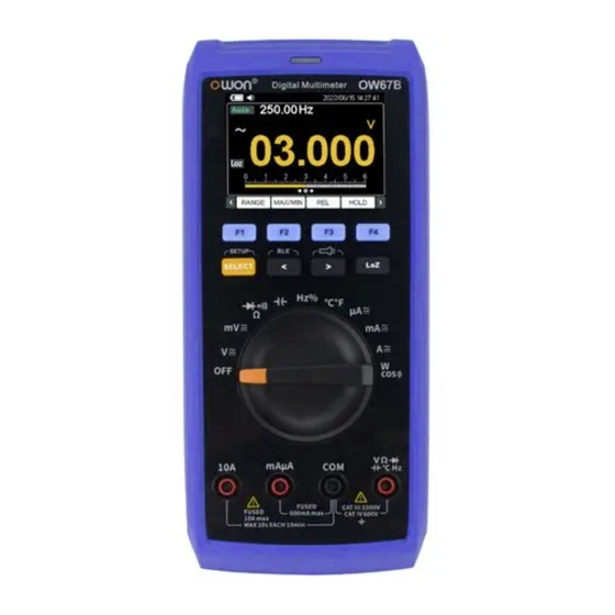
- Page 1 OW67 Series Digital Multimeters User Manual For product support, visit:www.owon.com.hk/download ※:The illustrations, interface, icons and characters in the user manual may be slightly different from the actual product. Please refer to the actual product.
- Page 2 LILLIPUT will continue to improve products and reserves the rights to change specification at any time without notice. is the registered trademark of the LILLIPUT Company. Fujian LILLIPUT Optoelectronics Technology Co., Ltd. No. 19, Heming Road Lantian Industrial Zone, Zhangzhou 363005 P.R. China Tel: +86-596-2130430 Fax: +86-596-2109272 Web: E-mail: www.owon.com.cn info@owon.com.cn...
-
Page 3: General Warranty
General Warranty We warrant that the product will be free from defects in materials and workmanship for a period of 1 year from the date of purchase of the product by the original purchaser from our company. This warranty only applies to the original purchaser and is not transferable to a third party. -
Page 4: Table Of Contents
Table of Contents 1. Safety Information .................... 1 Safety Considerations ....................1 Measurement Category ....................3 Safety Terms and Symbols ....................4 2. Quick Start ......................5 General Inspection ......................5 Install the Batteries ......................5 Adjusting the Tilt Stand ....................6 Power On/Off ........................6 Sleep Mode ........................ - Page 5 Maximum/Minimum Measurement ................24 Relative Measurement ....................25 Value Hold Mode ......................25 Comparative Measurement ..................26 Record Mode ......................... 26 Peak Measurement ....................... 26 Frequency Measurement ..................... 27 5. To Connect with Mobile Device ..............28 How to Connect ........................28 User Interface ........................... 30 Operations in APP ........................
-
Page 6: Safety Information
1.Safety Information 1. Safety Information Safety Considerations Before any operations, please read the following safety precautions to avoid any possible bodily injury and prevent damage to this product or any other products connected. To avoid any contingent danger, use this product only as specified. - Page 7 1.Safety Information When using the test leads, keep your fingers behind the finger guards on the test leads. Remove the test leads from the multimeter before you open the battery cover. To avoid false readings, which may lead to possible electric shock or personal ...
-
Page 8: Measurement Category
1.Safety Information Measurement Category The multimeter has a safety rating of 1000 V, CAT III and 600 V, CAT IV. Measurement category definition Measurement CAT I applies to measurements performed on circuits not directly connected to the AC mains. Examples are measurements on circuits not derived from the AC mains and specially protected (internal) mains- derived circuits. -
Page 9: Safety Terms And Symbols
1.Safety Information Safety Terms and Symbols Safety Terms Terms in this Manual. The following terms may appear in this manual: Warning: Warning indicates the conditions or practices that could result in personal injury or death. Caution: Caution indicates the conditions or practices that could result in damage to this product or other property. -
Page 10: Quick Start
2.Quick Start 2. Quick Start General Inspection After you get a new multimeter, make a check on the instrument according to the following steps: 1. Check whether there is any damage caused by transportation. If it is found that the packaging carton or the foamed plastic protection cushion has suffered serious damage, do not throw it away first till the complete device and its accessories succeed in the electrical and mechanical property tests. -
Page 11: Adjusting The Tilt Stand
2.Quick Start (2) Lift the tilt stand and loosen the screws with a suitable Phillips screwdriver and remove the battery cover. (3) Observe the battery polarity indicated inside the battery compartment, Insert the batteries. (4) Place the battery cover back in its original position and tighten the screws. Caution: To avoid instruments being damage from battery leakage, always remove the batteries and store them separately if the multimeter is not going to be used for a long period. -
Page 12: Low Impedance(Only For V-Voltage Scale
2.Quick Start flashlight.Press F4 to select EXIT or other functional measures to exit flashlight menu. Low impedance (Only for V-voltage scale) This function may only be used for voltages of a max. of 1,000 V and a max. of 3 seconds! This function enables reducing the measuring impedance from 10 MΩ... -
Page 13: Multimeter In Brief
2.Quick Start Multimeter in Brief Front panel Description: Description Display Screen. F1~F4: Menu selection key, press will activate the corresponding menu. : For switching different modes of the same tap in the turntable; hold down to enter the system setting. : For the bottom menu bar in the selection of the next page. -
Page 14: Interface
2.Quick Start the flashlight. : Press it to enter LoZ mode. : Power off. : DC or AC voltage measurement. : Diode/Continuity/Resistance measurement. : Capacitance measurement. Rotary :Frequency measurement. Switch : Temperature measurement. : DC or AC current measurement. : Power and power factor measurement. Input terminals. -
Page 15: Input Terminals
2.Quick Start Data hold enabled Display unit of measurement Display measured value Analog range bar Measurement menu ⑨ Low-pass ⑩ DC or AC mode ⑪ Auto range ⑫ Input terminals The terminal connections for the different measurement functions of the multimeter are described in the table below. - Page 16 2.Quick Start when measuring. DC Voltage Measurement AC Voltage Measurement DC Current Measurement AC Current Measurement Resistance Measurement Continuity Test...
-
Page 17: Setting Menu
2.Quick Start Diode Measurement Capacitance Measurement Frequency Measurement Temperature Measurement Setting menu Press and hold the SELECT button to enter the settings menu. The user can switch menus using the F1 or F2 buttons, and set the desired values using the F3 or F4 buttons. - Page 18 2.Quick Start there is no rotation or pressing any key within the preset time, the instrument will automatically shut down to reduce the power loss. Press the F3 or F4 button to select the number of minutes for the automatic shutdown time (5&10&15&30&Always ON). Set the automatic screen-off time.
- Page 19 2.Quick Start is turned on.
-
Page 20: Making Measurements
3.Making Measurements 3. Making Measurements Measuring AC or DC Voltage Warning: Do not measure any voltage of over 1000 Vdc or 750 Vac rms to avoid instrument damage or electric shock. Do not apply more than 1000 Vdc or 750 Vac rms between the common terminal and the earth ground to avoid instrument damage or electric shock. -
Page 21: Measuring Resistance
3.Making Measurements Measuring Resistance Caution: To avoid possible damage to your multimeter or to the equipment under test, disconnect the circuit power and discharge all high-voltage capacitors before measuring resistance. (1) Rotate the rotary switch to (2) Connect the black test lead to the terminal and the red test lead to the terminal. -
Page 22: Testing Diodes
3.Making Measurements testing mode, will be displayed. (2) Connect the black test lead to the terminal and the red test lead to the terminal. (3) Probe the test points to measure the resistance in the circuit. If the reading is below setting value, the multimeter will beep continuously. -
Page 23: Measuring Capacitance
3.Making Measurements (3) Connect the red test lead to the positive terminal (anode) of the diode and the black test lead to the negative terminal (cathode). The cathode of a diode is indicated with a band. (4) Read the diode forward bias. If the test lead connection is reversed, the multimeter will display "OL". -
Page 24: Measuring Frequency/Duty Cycle
3.Making Measurements (3) Probe the test points and read the display. Measuring Frequency/Duty Cycle (1) Rotate the rotary switch to (2) Connect the black test lead to the terminal and the red test lead to the terminal. -
Page 25: Measuring Temperature
3.Making Measurements (3) Probe the test points and read the display. (4) Press to switch between the frequency and duty cycle measurements. Note: To measure the frequency of signal with large amplitude, it is recommended to press FREQ to measure the frequency in AC voltage measurement mode. Measuring Temperature Any K-type thermosensor may be used for measuring temperatures. -
Page 26: Measuring Power And Power Factor
3.Making Measurements Caution: To avoid possible damage to the multimeter or to the equipment under test, check the multimeter’s fuse before measuring current. Use the proper terminals, function, and range for your measurement. Never place the test leads in parallel with any circuit or component when the leads are plugged into the current terminals. -
Page 27: Measure Dc Power
3.Making Measurements “COM” into the test socket and the test lead “V” into the test socket. (3) Then plug the measuring adapter into a properly earthed protective contact socket. (4) Plug the load to be measured into the measuring adapter. Make sure that the load is switched off to prevent arcing when plugging it in. -
Page 28: Measure Usb Power
3.Making Measurements (6) Switch the DC power supply and test load ON. (7) On the multimeter: The main display will show the active power in W and the sub-display will show the current A. Press F1 to toggle between “V” (voltage) and “W” (active power). (8) When finished testing,de-energise the measurement setup, then disconnect the cables and switch the multimeter OFF. -
Page 29: The Multimeter Function
4.The Multimeter Function 4. The Multimeter Function The following functions are explained using the voltage range as an example. Please refer to the voltage measurement mode for other measurement modes. Set Range 1. Rotate the rotary switch to 2. Press SELECT to switch to the DC voltage measurement mode. 3. -
Page 30: Relative Measurement
4.The Multimeter Function Relative Measurement When making relative measurements, reading is the difference between a stored reference value and the input signal. 1. Rotate the rotary switch to 2. Press SELECT to switch to the DC voltage measurement mode. 3. Press < or > to switch to the first page menu. 4. -
Page 31: Comparative Measurement
4.The Multimeter Function 5. Press F4 again to exit the mode. Comparative Measurement 1. Rotate the rotary switch to 2. Press and hold SELECT to enter setup interface,then press F1 or F2 to select Compare Type, Compare Min and Compare Max to set comparison value type and range. -
Page 32: Frequency Measurement
4.The Multimeter Function This function only for AC/AC+DC measurement mode. 1. Rotate the rotary switch to 2. Press SELECT to switch to AC voltage measurement mode. 3. Press < or > to switch to the first page menu. 4. Press F2 and select PEAK, The Max icon and the current measurement appear in the upper-left corner of the screen, and the maximum value is displayed on the screen. -
Page 33: To Connect With Mobile Device
5.To Connect with Mobile Device 5. To Connect with Mobile Device Bluetooth model supports communications with Android or iOS based smart device through Bluetooth. You can use the free application software on the smart devices to monitor the measurements, perform remote control, view trending graphs, etc. The recorded data can be saved as CSV file. - Page 34 5.To Connect with Mobile Device (6) If the Bluetooth of the mobile device is not enabled, a prompt box will pop up at the bottom, indicating "Bluetooth is not turned on". You need to manually open the Bluetooth of the mobile device before connection can be made. (7) Active "Filter device"...
-
Page 35: User Interface
5.To Connect with Mobile Device User Interface... -
Page 36: Function Description Table
5.To Connect with Mobile Device Function Description Table Display Function Display Function Direct Current Measuring Capacitance Alternating Current Measuring Frequency Measuring DUTY Measuring Duty Cycle Resistance DIODE Testing Diodes TEMP Measuring Temperature CONT Testing for Continuity Power Measuring power Operations in APP ... - Page 37 5.To Connect with Mobile Device corner of the single-view screen. Go to the “More settings” interface. Click the “Modify device name”. Go to “Modify device name”interface,enter a user-defined device name. Click the save icon in the upper right corner of the page to modify the device name.
- Page 38 5.To Connect with Mobile Device screen or in the upper right corner to enter more Settings and enable or disable voice broadcast. Alert: In setting interface, you can enable the alert notification, and set the upper/lower limit. APP will alert for any out-of-limit event. Click in the upper right corner of the single-view screen Go to the “More settings”...
- Page 39 5.To Connect with Mobile Device Click to set the required value and mode of "Upper limit, Lower limit, Alarm Mode" (within range & Outside range). Click on"Alarm Mode"and select a range condition: "Inside": sound alarm if reading falls within the lower and upper limit; ...
- Page 40 5.To Connect with Mobile Device Multimeter Offline Record When measuring with BDM, you can use device APP to send a command, the multimeter will start recording the measurements. After receiving the command, the connection will be disconnected automatically. The multimeter will record the measuring data in its own memory.
- Page 41 5.To Connect with Mobile Device Note: If the multimeter is in the process of recording data and not finished yet, connect the Mobile device and the multimeter, a dialog box will pop up: Select , the recording process will be interrupted. The Mobile device will connect with the multimeter to read data.
- Page 42 5.To Connect with Mobile Device (7) Tap on , the data will be displayed in Data Graph and Table interface. Add meter: Click the "+" in the top left corner to start the search for devices and list the multimeters found. ...
- Page 43 5.To Connect with Mobile Device softkeys, as Hold, Rel, Select, etc.) can be short or long pressed to perform control, just as press the corresponding keys of multimeter. Data Graph and Table: Click Data Chart to view data graph and table. ...
- Page 44 5.To Connect with Mobile Device (1) Click ”Open File”. (2) Go to “Files”interface. (3) Select data files (Offline record files & Online record files) as required. The following uses Online record files as an example: Click "Online record files" on the Local Files screen. ...
- Page 45 5.To Connect with Mobile Device On the data file editing page, you can Load data, Share, Rename, Remone, and Cancel data files. Setting: Click Setting to setting interface.
- Page 46 5.To Connect with Mobile Device Data Chart record interval:Click Data Chart record interval , Set the recording interval in the display box below (setting range: 1S~11H:59M:59S). After setting the required interval, click ”OK”. Click Cancel or click anywhere outside the Settings box to cancel the current Settings.
- Page 47 5.To Connect with Mobile Device Data Chat record count : Click the number of records and set the number of records for real-time data in the display box below (set range: 100-3000). After setting the required number of records, click “OK”. Click Cancel or click anywhere outside the Settings box to cancel the current Settings.
- Page 48 5.To Connect with Mobile Device Auto save:Enable or disable the automatic storage of real-time data. ON-State OFF-State Setting Period: Click "Period" and set the recording Period in the display box below (setting range: 1S~11H:59M:59S). After setting the required Period, click "OK”.
- Page 49 5.To Connect with Mobile Device A few times:Click “A few times” and set the storage times in the display box below (set range: Once&10&20&30). After setting the required storage times, click “OK”. Click Cancel or click anywhere outside the Settings box to cancel the current Settings.
- Page 50 5.To Connect with Mobile Device Theme: Click to select display theme as "Night" or "Day ", click "Save" to finish setting. About: Click for information about the instrument. Exit: Click to exit the current application.
-
Page 51: Technical Specifications
6.Technical Specifications 6. Technical Specifications All these specifications apply to the multimeter unless otherwise explanation. Standard conditions: The environment temperature is 18℃ to 28℃, the relative humidity is less than 80%. Note: When measuring AC voltage/current or capacitance, accuracy guarantee range is 5% to 100% of the range. - Page 52 6.Technical Specifications 6.0000kΩ 0.0001 kΩ ±(0.3%+10dig) 60.00kΩ 0.01 kΩ 600.0kΩ 0.1 kΩ ±(0.2%+5dig) 6.000MΩ 0.001 MΩ ±(0.6%+5dig) 60.00MΩ 0.01 MΩ ±(1.5%+7dig) 6.0000nF 0.0001nF ±(5.0%+100dig) 60.000nF 0.001nF 600.00nF 0.01nF ±(2.5%+20dig) 6.0000μF 0.0001μF Capacitance(F) 60.000μF 0.001μF ±(2.0%+20dig) 600.00μF 0.01μF ±(2.5%+20dig) 6000.0μF 0.1μF ±(4.0%+20dig) 60.000mF 0.001mF...
-
Page 53: General Specification
6.Technical Specifications Power 0 - 2500.0W 0.1W ±(2.0%+10dig) Voltage 0 - 250.0V 0.1V DC Power ±(1.0%+10dig) Current 0 - 10.0 A 0.1 A ±(2.0%+10dig) Power 240.0W 0.1W ±(0.5%+5dig) Voltage 48.00V 0.01V ±(1.0%+5dig) Current 5.00 A 0.01 A Power 0-99999mAh 1mAh Capacity 0-1000Wh 99h59m59s... - Page 54 6.Technical Specifications Data Hold √ Relative Measurement √ Backlight √ Input Protection √ Input Impedance ≥ 10 MΩ Analog Bar √ Dual Display √ Maximum Hold √ Minimum Hold √ Peak (1ms) √ Manual Ranging √ Auto Power Off √ Mis-Lead Insert Alert √...
-
Page 55: Appendix
7.Appendix 7. Appendix Appendix A: Enclosure Standard Accessories: K-type Multimeter Quick guide Battery Soft Bag thermocouple Leads Option Accessories: AC Power USB Power DC Power Measurement Measurement Measurement Module Module Module Appendix B: General Care and Cleaning Warning: To avoid electrical shock or damage to the multimeter, ensure that the insides of the casing stay dry at all times.
Need help?
Do you have a question about the OW67 Series and is the answer not in the manual?
Questions and answers