EDA ED-HMI3020-070C User Manual
7-inch high-performance industrial panel pc based on raspberry pi 5
Hide thumbs
Also See for ED-HMI3020-070C:
- Application manual (28 pages) ,
- Application manual (29 pages) ,
- Service manual (15 pages)

Related Manuals for EDA ED-HMI3020-070C


Summary of Contents for EDA ED-HMI3020-070C
- Page 1 ED-HMI3020-070C 7-inch High-Performance Industrial Panel PC Based on Raspberry Pi 5 User Manual EDA Technology Co., LTD March 2024...
- Page 2 IOT, industrial control, automation, green energy and artificial intelligence based on Raspberry Pi technology platform. You can contact us in the following ways: EDA Technology Co.,LTD Address: Building 29, No.1661 Jialuo Road, Jiading District, Shanghai Mail: sales@edatec.cn...
- Page 3 Copyright Statement ED-HMI3020-070C and its related intellectual property rights are owned by EDA Technology Co.,LTD. EDA Technology Co.,LTD owns the copyright of this document and reserves all rights. Without the written permission of EDA Technology Co.,LTD, no part of this document may be modified, distributed or copied in any way or form.
- Page 4 EDA Technology Co.,LTD does not guarantee that the information in this manual is up to date, correct, complete or of high quality. EDA Technology Co.,LTD also does not guarantee the further use of this information. If the material or non-...
-
Page 5: Reader Scope
ED-HMI3020-070C to help users understand the overall system parameters of the products. This document introduces the appearance, installation, startup ED-HMI3020-070C User Manual and configuration of ED-HMI3020-070C to help users use the product better. This document introduces downloading OS file, flashing to SD ED-HMI3020-070C Application Guide card, Firmware Update, and Configuring booting from SSD of ED- HMI3020-070C to help users use the product better. -
Page 6: Related Agreement
Related Agreement Symbolic Convention Symbolic Instruction Prompt symbols, indicating important features or operations. Notice symbols, which may cause personal injury, system damage, or signal interruption/loss. Warning symbols, which may cause great harm to people. -
Page 7: Safety Instructions
Safety Instructions This product should be used in an environment that meets the requirements of design specifications, otherwise it may cause failure, and functional abnormality or component damage caused by non-compliance with relevant regulations are not within the product quality assurance scope. ... -
Page 8: Table Of Contents
Content Foreword ..............................i Related Manuals ..........................i Reader Scope ............................i Related Agreement ..........................ii Symbolic Convention ........................ii Safety Instructions ............................. iii Product Description ......................... 1-1 Overview ........................... 1-2 Packing List ........................1-3 Appearance ........................1-4 1.3.1 Front Panel ........................ 1-4 1.3.2 Rear Panel ......................... - Page 9 5.1.1 View IP address at the Network icon of Desktop ............5-2 5.1.2 Hostname command to query ..................5-3 5.1.3 Query IP by Using ifconfig Command ................ 5-3 5.1.4 Query IP by Using Network Manager CLI ..............5-4 5.1.5 Login Router to Query IP ................... 5-4 5.1.6 Scan For Using NMAP Tool ..................
-
Page 10: Product Description
1 Product Description 1 Product Description This chapter introduces the product overview, packing list, appearance, button, indicator and interfaces. Overview Packing List Appearance Button Indicator Interface ED-HMI3020-070C User Manual... -
Page 11: Overview
1 Product Description 1.1 Overview ED-HMI3020-070C is a 7-inch high-performance industrial panel PC based on Raspberry Pi 5. According to different application scenarios and user needs, different specifications of RAM, SD card and SSD can be selected. 4GB and 8GB RAM are optional ... -
Page 12: Packing List
1 Product Description 1.2 Packing List 1x ED-HMI3020-070C Unit 4 x buckles (including 4xM4*8 screws and 4xM4*16 screws) ED-HMI3020-070C User Manual... -
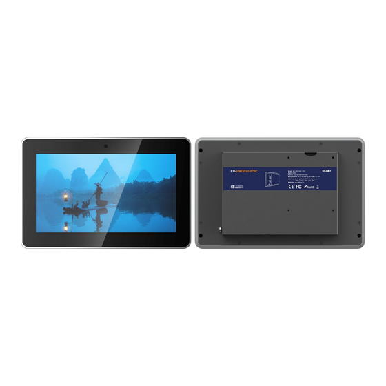
Page 13: Appearance
1 x LCD display, 7-inch LCD touch screen, which supports up to 1024x600 resolution and multi-point capacitive touchscreen. 1 x camera (optional), 8 Megapixel front camera. 1.3.2 Rear Panel This section introduces interfaces and definitions of rear panel. ED-HMI3020-070C User Manual... -
Page 14: Side Panel
1 Product Description Function Definition 4 x installation holes of buckle, which are used to fix the buckles to the device for installation. 1.3.3 Side Panel This section introduces interfaces and definitions of side panel. ED-HMI3020-070C User Manual... - Page 15 1 x Micro SD card slot, which is used to install SD card. It supports booting the OS from SD card. 2 x HDMI ports, micro-HDMI connector, which can connect a display and supports 4K 60Hz. 1 x DC input, USB Type-C connector, which supports 5V 5A power input. ED-HMI3020-070C User Manual...
-
Page 16: Button
1 Product Description 1.4 Button The ED-HMI3020-070C includes a ON/OFF button, and the silkscreen is “ON/OFF”. If you run Raspberry Pi Desktop, you can initiate a clean shutdown by briefly pressing the power button. A menu will appear asking whether you want to shutdown, reboot, or logout: TIP: If you run Raspberry Pi Desktop, you can press the power button twice in quick succession to shut down. -
Page 17: Indicator
1 Product Description 1.5 Indicator This section introduces various statuses and meanings of indicators contained in ED-HMI3020-070C. Indicator Status Description The device has been powered on. Power supply of the device is abnormal, please stop the power supply Blink immediately. -
Page 18: Interface
”, which supports the installation of an SD card for booting the system. 1.6.2 Power Supply The ED-HMI3020-070C includes one power input, and the silkscreen is “PWR IN”. The connector is USB Type-C, which supports 5V 5A power input. TIP: In order for Raspberry Pi 5 to achieve better performance, it is recommended to use a 5V 5A power adapter. -
Page 19: Hdmi
1 Product Description 1.6.4 HDMI ED-HMI3020-070C includes 2 HDMI ports, and the silkscreen is "HDMI". The connector is micro- HDMI, which can connect to HDMI displays and supports up to 4Kp60. 1.6.5 USB 2.0 ED-HMI3020-070C includes 2 USB 2.0 ports, and the silkscreen is "... -
Page 20: Rs485
Device 1 RS485 Terminal Resistor ED-HMI3020-070C contains a RS485 port. A 120R jumper resistor is reserved between A and B of RS485 line. The jumper cap can be inserted to enable the jumper resistor. By default, the ED-HMI3020-070C User Manual... -
Page 21: Audio In
”, supporting stereo audio output. 1.6.11 Speaker The ED-HMI3020-070C contains a power amplifier output, built-in a 4Ω 3W speaker, supporting single-channel stereo output. When playing audio, if the headphone is connected to the Audio Out interface (HPO), the speaker will have no audio output. -
Page 22: Installing/Removing Components (Optional)
2 Installing/Removing Components (optional) This chapter introduces how to install/remove components. Pull Out SD Card Insert SD Card Open Device Case Remove SSD Install SSD Install RTC Battery Close Device Case ED-HMI3020-070C User Manual... -
Page 23: Pull Out Sd Card
Please turn off the power before inserting or removing the SD card. Preparation: The device has been disconnected from power. Steps: Find the location of the SD card, as shown in red mark of figure below. Hold the SD card and pull it out. ED-HMI3020-070C User Manual... - Page 24 2 Installing/Removing Components (optional) ED-HMI3020-070C User Manual...
-
Page 25: Insert Sd Card
Find the location of the SD card slot, as shown in red mark of figure below. Insert the SD card into the corresponding card slot with the contact side facing down, making sure it will not fall out. ED-HMI3020-070C User Manual... - Page 26 2 Installing/Removing Components (optional) ED-HMI3020-070C User Manual...
-
Page 27: Open Device Case
Use a screwdriver to loosen four M3 screws and one grounding screw on two sides counterclockwise, as shown in the red mark in the figure below. Remove the metal case upward and flip it clockwise to the PCBA side. ED-HMI3020-070C User Manual... - Page 28 2 Installing/Removing Components (optional) Use a screwdriver to loosen 6 screws of PCBA mounting counterclockwise to separate the PCBA from the metal case, and flip it to the back of PCBA. ED-HMI3020-070C User Manual...
-
Page 29: Remove Ssd
Find the location of SSD, as shown in the red mark of figure below. Use a screwdriver to loosen the screws that secure the SSD counterclockwise. Hold both sides of the SSD with your hands and pull it out in the direction of the arrow. ED-HMI3020-070C User Manual... - Page 30 2 Installing/Removing Components (optional) ED-HMI3020-070C User Manual...
-
Page 31: Install Ssd
A cross screwdriver has been prepared. SSD is ready. Steps: Find the location of SSD connector, as shown in the red mark of figure below. Use a screwdriver to loosen the screws that secure the SSD counterclockwise. ED-HMI3020-070C User Manual 2-10... - Page 32 2 Installing/Removing Components (optional) Insert the SSD into the connector with the contacts facing up. Insert the screws that secure the SSD and tighten clockwise to secure the SSD to the PCBA. ED-HMI3020-070C User Manual 2-11...
-
Page 33: Install Rtc Battery
Find the location of RTC battery base, as shown in the red mark of figure below. Place the positive terminal of the battery facing up, and press it into the RTC base. The completed installation is as shown below. ED-HMI3020-070C User Manual 2-12... - Page 34 2 Installing/Removing Components (optional) ED-HMI3020-070C User Manual 2-13...
-
Page 35: Close Device Case
LCD screen, and cover it downward on the back of the LCD screen. Use a screwdriver to tighten four M3 screws and one grounding screw on two sides clockwise. ED-HMI3020-070C User Manual 2-14... - Page 36 Align the ports on the PCBA with the port’s holes on the side panel, and insert the side cover. Use a screwdriver to tighten 2 M3 screws clockwise to fix the side cover. Plug in the default configuration of phoenix connector. ED-HMI3020-070C User Manual 2-15...
-
Page 37: Installing Device
3 Installing Device 3 Installing Device This chapter introduces how to install the device. Embedded Installation ED-HMI3020-070C User Manual... -
Page 38: Embedded Installation
A cross screwdriver has been prepared. Steps: You need ensure the opening size of the cabinet according to the size of ED-HMI3020-070C, as shown in the figure below. Unit: mm Drill a hole on the cabinet according to the hole size of step1. - Page 39 Use 4 M4x8 screws to pass through the buckle and tighten it clockwise to fix the buckle to the device; then use 4 M4x16 screws to pass through the screw hole (threaded hole) of the buckle and tighten clockwise to the end through the buckles. ED-HMI3020-070C User Manual...
- Page 40 3 Installing Device ED-HMI3020-070C User Manual...
-
Page 41: Booting The Device
4 Booting The Device 4 Booting The Device This chapter introduces how to connect cables and boot the device. Connecting Cables Booting The System For The First Time ED-HMI3020-070C User Manual... -
Page 42: Connecting Cables
A network that can be used normally. Get the HDMI cable and network cable that can be used normally. Schematic diagram of connecting cables: Please refer to 1.6 Interface for the pin definition of each interface and the specific method of wiring. ED-HMI3020-070C User Manual... -
Page 43: Booting The System For The First Time
4 Booting The Device 4.2 Booting The System For The First Time After ED-HMI3020-070C is connected to the power supply, the system will start. The red PWR indicator is on, indicating that the device has been powered normally. The green ACT indicator is blinking, indicating that the system is started normally, and then the logo will appear in the screen. -
Page 44: Configuring System
This chapter introduces how to configure system. Finding Device IP address Remote Login Configuring Wi-Fi Configuring Ethernet IP Configuring Bluetooth Configuring Buzzer Configuring RTC Configuring Serial Port Configuring Audio Configuring SSD (optional) ED-HMI3020-070C User Manual... -
Page 45: Finding Device Ip Address
TIP: Only supported by Desktop version system. Preparation: ED-HMI3020-070C has been connected to the network through the router. Steps: Hover over the network icon in the system tray, and a tooltip will appear. This tooltip displays the name of the network you’re currently connected to and your IP address. -
Page 46: Hostname Command To Query
After the device starting normally and the display is connected, you can query the current device IP address by using hostname command. Preparation: ED-HMI3020-070C has been connected to the network through the router. Steps: Run the following command in the command pane to obtain IP address. -
Page 47: Query Ip By Using Network Manager Cli
The IP and network password of the router in the network have been obtained, and the IP address is 192.168.X.X. Steps: Open a browser, Enter the router IP of the network where ED-HMI3020-070C is in the ED-HMI3020-070C User Manual... -
Page 48: Scan For Using Nmap Tool
192.168.x.x, and press Enter to enter the router login interface. According to the interface prompts, enter the network password and enter the router management interface. Find the IP address of ED-HMI3020-070C in the terminal device of the management interface. 5.1.6 Scan For Using NMAP Tool When the device starts normally but the display is not connected, you can use Nmap tool to scan the IP under the current network to obtain the IP information of the device. -
Page 49: Remote Login
The tools for remote login are selected by users themselves, and the following is an example of logging in through MobaXterm. Preparation: The MobaXterm tool has been installed on the PC. ED-HMI3020-070C has been connected to the network through the router. IP address of ED-HMI3020-070C has been get. Steps: Open MobaXterm, click and open the window for creating connection, as shown in the figure below. - Page 50 5 Configuring System After entering the IP address of ED-HMI3020-070C, click "OK". Click "Accept" in the pop-up prompt box to enter the system login interface. Enter the username and password according to the prompt, and enter the system after logging in.
-
Page 51: Connecting To The Device Desktop Through Vnc
The RealVNC Viewer tool has been installed on PC. ED-HMI3020-070C has been connected to the network through the router. IP address of ED-HMI3020-070C has been get. The VNC function in the ED-HMI3020-070C system has been turned on, as shown in the following figure. Steps: Open RealVNC Viewer and select "New connection…"... - Page 52 5 Configuring System After entering the IP address of ED-HMI3020-070C, click "OK". Enter the username and password in the Authentication prompt box that pops up. ED-HMI3020-070C User Manual...
- Page 53 5 Configuring System TIP: Default username is pi, Default password is raspberry. Select "OK" to log in and connect to the remote desktop. ED-HMI3020-070C User Manual 5-10...
-
Page 54: Configuring Wi-Fi
5 Configuring System 5.3 Configuring Wi-Fi ED-HMI3020-070C supports Wi-Fi function by default, and you need to configure it before using Wi- 5.3.1 Enable Wi-Fi The Wi-Fi function is blocked by default, and you need to set the country region to enable it. You can open the configuration windows through the desktop icon for settings. - Page 55 Enter the Wi-Fi Password in the pop-up "Wi-Fi Network Authentication Required" pane. Click “Connect” to connect the network. After the connection is completed, the Wi-Fi icon will be displayed normally in the upper right corner of the desktop. ED-HMI3020-070C User Manual 5-12...
-
Page 56: Configuring Ethernet Ip
In the pop-up "Editing Wired connection" pane, select the "IPv4 Settings" page, and then set the IP address as required. If you want to set the IP as a static IP, set the "Method" as "Manual", add an entry in ED-HMI3020-070C User Manual 5-13... - Page 57 If you want to set the IP to automatic acquisition mode, you only need to set the "Method" as "Automatic(DHCP) ". Click "save" to return to "Network Connections" pane and close the page. Execute the sudo reboot command to restart the device. ED-HMI3020-070C User Manual 5-14...
-
Page 58: Configuring Bluetooth
5 Configuring System 5.5 Configuring Bluetooth ED-HMI3020-070C supports Bluetooth function, which is enabled by default. You need to finish related configurations such as adding devices, scanning devices and device pairing before using Bluetooth. Steps: Left-click the icon in the upper right corner of the desktop and select “Add Device” in the pop-up menu. - Page 59 5 Configuring System Left-click the icon in the upper right corner of the desktop to view the connected Bluetooth device. ED-HMI3020-070C User Manual 5-16...
-
Page 60: Configuring Buzzer
5 Configuring System 5.6 Configuring Buzzer ED-HMI3020-070C contains a buzzer, which supports manually configure the buzzer to turn on and off. Execute the following commands to detect and install gpiod tools. sudo apt update sudo apt install gpiod Execute the following commands to check the number of gpiochip. -
Page 61: Configuring Rtc
5 Configuring System 5.7 Configuring RTC ED-HMI3020-070C contains an integrated RTC, which automatically reads the system time synchronously by default, and you can manually read and write the system time into RTC. Execute the following command to read the RTC time manually. -
Page 62: Configuring Serial Port
Execute the following command to install the picocom tool. sudo apt-get install picocom 5.8.2 Configuring RS232 ED-HMI3020-070C contains 1 RS232 port, and its corresponding COM port and device file are detailed in the following table. Number of RS232 port Corresponding COM Port... - Page 63 Corresponding Device File /dev/com2 COM2 Preparation: The RS485 port of ED-HMI3020-070C has been connected with external device. Steps: 1. Execute the following command to open the serial port com2, and configure the serial port baud rate to 115200. picocom -b 115200 /dev/com2 2.
-
Page 64: Configuring Audio
5 Configuring System 5.9 Configuring Audio ED-HMI3020-070C contains one audio input (supports access to MIC) and one audio output. The volume of Master and MIC can be adjusted, and it supports audio recording of MIC. 5.9.1 Adjusting The Volume It supports manual adjustment of MIC and Master volume. -
Page 65: Configuring Recording
The audio input interface is connected to the MIC, and the MIC is not muted. Steps: 1. Execute the following command to start recording audio named name.wav, as shown in the figure below. arecord -fdat -Dhw:0 --vumeter=stereo name.wav ED-HMI3020-070C User Manual 5-22... - Page 66 Indicating the recorded file name, which can be customized by the user. 2. Input Ctrl+C to save and close the recording. 3. Execute the following command to obtain the storage path of the recording file. ED-HMI3020-070C User Manual 5-23...
-
Page 67: Configuring Ssd (Optional)
5 Configuring System 5.10 Configuring SSD (optional) ED-HMI3020-070C supports optional SSD. If the product model contains an SSD, you need to finish creating partition, formatting and mounting before using SSD. 5.10.1 Creating Partition Preparation: ED-HMI3020-070C contains an SSD. Steps: 1. Run the following command to view all disk partitions on the ED-HMI3020-070C. -
Page 68: Formatting
After executing the command, if the “TYPE” column does not display “part”, it means that the partition is failed. 5.10.2 Formatting The SSD of ED-HMI3020-070C by default is not formatted. After the disk partition is completed, it needs to be formatted into ext4 format. Preparation: Disk partitioning of SSD has been completed. -
Page 69: Mounting Ssd
Execute the following command to format the SSD named nvme0n1p1 into ext4 format. sudo mkfs.ext4 /dev/nvme0n1p1 5.10.3 Mounting SSD The SSD of ED-HMI3020-070C by default needs to be configured to mount SSD in a specific folder, usually in the “/mnt” folder (such as “/mnt/SSD”). Preparation: Partitioning and formatting of the SSD have been completed. - Page 70 After executing the command, if the display information lists the mount point “/mnt/SSD”, it means the mount of SSD is successful. After executing the command, if the displayed information does not list the mount point information, it means that the mount of SSD is failed. ED-HMI3020-070C User Manual 5-27...
Need help?
Do you have a question about the ED-HMI3020-070C and is the answer not in the manual?
Questions and answers