Advertisement
Quick Links
Download this manual
See also:
Troubleshooting Manual
7" FLAT PANEL COLOR OBSERVATION
MONITOR OWNER'S MANUAL
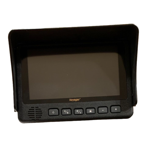
AOM701 Features:
– 7" High Performance Color LCD
– Built-in Audio Speaker with V olume Control
and 12V Trigger
– 2 Camera (A/V) Input with A/B Select Control
– Backlit Controls and Day/Night Picture Modes
for Nighttime Use
– Auto/Manual Power On
– Sun Visor Included
UDIOVOX
PECIALIZED
PPLICATIONS, L.L.C.
AOM701
A
B
Visit us at http://www.asaelectronics.com
Patent Pending
e 4
®
+
–
Advertisement

Related Manuals for Voyager AOM701


Summary of Contents for Voyager AOM701
- Page 1 ® AOM701 7” FLAT PANEL COLOR OBSERVATION MONITOR OWNER'S MANUAL – AOM701 Features: – 7” High Performance Color LCD – Built-in Audio Speaker with V olume Control and 12V Trigger – 2 Camera (A/V) Input with A/B Select Control – Backlit Controls and Day/Night Picture Modes for Nighttime Use –...
- Page 2 The AOM701 product is designed to be used primarily as a rear observation device in conjunction with closed circuit cameras. In any installations where the AOM701 is used to display television broadcasts or recorded video playback, installation location must adhere to local laws and regulations.
- Page 3 PA C K I NG C ONT E NT S: 90 DAY/ 12 MONT H LIMIT E D WAR R ANT Y WA R R A NT Y CA R D L CD MONIT OR SUN SHIE L D 4” X 2” V E L CR O QT Y .
-
Page 4: Controls And Operation
Stand-by mode - Turned on by a stand by trigger wire generally connected to the vehicles 12V reverse backup lights. Manual Mode wiring - For manual mode operation, the AOM701 should be wired as follows: ACC (+12V) Red wire should be connected to the vehicles accessory feed. - Page 5 These buttons also serve as adjustment controls while in the Picture Adjustment Menu mode (see above section for details). *Note: The AOM701 requires +12V to be applied to the “Audio Enable” trigger input in order to activate the built-in speaker. If no audio output is heard from the...
- Page 6 11. Install the PanaVise® mount to the LCD monitor using the #10 self-drilling screws (included). **Important: Do not use screws other than those provided with the AOM701. Void of warranty and serious product damage will occur.
- Page 7 5’ intermediate cable included with the AOM701 to connect the monitor to the connection cable. If more cable length is needed, additional 5’ lengths of the intermediate cable can be purchased.
- Page 8 (+12V) AUDIO (+12V) TRIGGER STANDBY (+12V) TRIGGER...
- Page 9 REAR OBSERVATION INSTALLATION DISTANCE MARKER USE/INSTALLATION - PLACE INDICATOR MARKERS (CONE, BOX ANY REFERENCE OBJECT HANDY) BEHIND VEHICLE AS IN FIGURE A. - PLACE RANGE MARKER DECALS ON SCREEN OF MONITOR OVER IMAGE OF INDICATOR MARKERS ON GROUND BEHIND VEHICLE, AS VIEWED ON THE MONITOR SCREEN.
- Page 10 ® PANA VISE MOUNT TEMPLATE (OPTIONAL ACCESSORY) 0.25 0.25 2.00 2.50 2.00 0.25 2.50...
-
Page 11: Troubleshooting
TROUBLESHOOTING SYMPTOM CAUSE SOLUTION No power No +12V accessory, No Replace circuit fuse, monitor has protection ground, mis-wired/reversed device built-in/reset, check ground connection, verify power is being supplied Video/No audio Blue/white audio trigger wire Connect to +12V ACC or reverse light circuit, not powered, Volume adjust turn volume adjustment up down... -
Page 12: Product Specifications
PRODUCT SPECIFICATIONS LCD panel specifications: Size/Type 7” (diagonal) /TFT LCD Brightness 350 nit (min) 420 nit (typ.) Contrast Ratio 200 (min) 300 (typ.) View Angles Top (12 o’clock): 30 (min) (@ CR 10) Bottom (6 o’clock): 50 (min) Horizontal: 50 (min) Response Time Rise: 12ms (typ.) ;...
Need help?
Do you have a question about the AOM701 and is the answer not in the manual?
Questions and answers