Dell Dimension 3100 Owner's Manual
Dell owner's manual network adapter 3100, e310
Hide thumbs
Also See for Dimension 3100:
- Service manual (94 pages) ,
- Technical manualbook (22 pages) ,
- Setup and specifications (21 pages)
Table of Contents
Advertisement
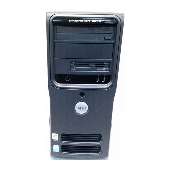
Dell™ Dimension™ 3100/E310
Service Tag
CD or DVD activity light
CD or DVD activity light
FlexBay for optional
floppy drive or Media
Card Reader
headphone connector
diagnostic lights
cover latch release
card slots for
PCI (2),
PCI Express x1 (1)
Model DCSM
w w w . d e l l . c o m | s u p p o r t . d e l l . c o m
Owner's Manual
CD or DVD eject button
USB 2.0 connectors (2)
1
2
3
4
hard drive activity light
power button
power connector
sound-card connectors
USB 2.0 connectors (4)
network adapter
VGA video connector (integrated)
Advertisement
Table of Contents
Troubleshooting

Related Manuals for Dell Dimension 3100


Summary of Contents for Dell Dimension 3100
- Page 1 Dell™ Dimension™ 3100/E310 Service Tag CD or DVD activity light CD or DVD activity light FlexBay for optional floppy drive or Media Card Reader headphone connector diagnostic lights cover latch release card slots for PCI (2), PCI Express x1 (1) Model DCSM w w w .
-
Page 2: Notes, Notices, And Cautions
Trademarks used in this text: Dell, the DELL logo, Inspiron, Dell Precision, Dimension, OptiPlex, Latitude, PowerEdge, PowerVault, PowerApp, DellNet, and PowerConnect are trademarks of Dell Inc.; Intel and Pentium are registered trademarks of Intel Corporation; Microsoft, Windows, and Outlook are registered trademarks of Microsoft Corporation. -
Page 3: Table Of Contents
Contents Finding Information Setting Up and Using Your Computer Setting Up a Printer Printer Cable ....... . Connecting a USB Printer Connecting to the Internet Setting Up Your Internet Connection... - Page 4 Configuring Your Computer for RAID Using the Intel Matrix Storage Manager Hyper-Threading ....... . . Solving Problems Troubleshooting Tips Battery Problems...
- Page 5 Restoring Your Operating System ® Using Microsoft Windows Using Dell™ PC Restore by Symantec Removing Dell PC Restore Removing and Installing Parts Before You Begin ....... . .
- Page 6 Cards ........Drive Panels .
- Page 7 ....... Dell Technical Support Policy (U.S. Only) Definition of "Dell-Installed" Software and Peripherals Definition of "Third-Party"...
- Page 8 Contents...
-
Page 9: Finding Information
• Warranty information • Terms and Conditions (U.S. only) • Safety instructions • Regulatory information • Ergonomics information • End User License Agreement • How to set up my computer Find It Here Dell™ Product Information Guide Setup Diagram Finding Information... - Page 10 Select your region to view the appropriate support site. NOTE: Corporate, government, and education customers can also use the customized Dell Premier Support website at premier.support. dell.com. To download Desktop System Software: Go to support.dell.com and click Downloads. Enter your Service Tag or product model.
- Page 11 What Are You Looking For? • How to use Windows XP • How to work with programs and files • How to personalize my desktop Find It Here Windows Help and Support Center Click the Start button and click Help and Support. Type a word or phrase that describes your problem and click the arrow icon.
- Page 12 Finding Information...
-
Page 13: Setting Up And Using Your Computer
Setting Up and Using Your Computer Setting Up a Printer NOTICE: Complete the operating system setup before you connect a printer to the computer. See the documentation that came with the printer for setup information, including how to: • Obtain and install updated drivers •... -
Page 14: Connecting To The Internet
Connecting to the Internet NOTE: ISPs and ISP offerings vary by country. To connect to the Internet, you need a modem or network connection and an Internet service provider (ISP), such as AOL or MSN. Your ISP will offer one or more of the following Internet connection options: •... -
Page 15: Setting Up Your Internet Connection
Setting Up Your Internet Connection To set up an AOL or MSN connection: 1 Save and close any open files, and exit any open programs. 2 Double-click the MSN Explorer or AOL icon on the Microsoft 3 Follow the instructions on the screen to complete the setup. If you do not have an MSN Explorer or AOL icon on your desktop or if you want to set up an Internet connection with a different ISP: 1 Save and close any open files, and exit any open programs. -
Page 16: Playing Cds And Dvds
Playing CDs and DVDs NOTICE: Do not press down on the CD or DVD tray when you open or close it. Keep the tray closed when you are not using the drive. NOTICE: Do not move the computer when you are playing CDs or DVDs. 1 Press the eject button on the front of the drive. -
Page 17: Adjusting The Volume
Eject Go to the next track A DVD player includes the following basic buttons: Stop Restart the current chapter Play Fast forward Pause Fast reverse Advance a single frame while in pause mode Go to the next title or chapter Continuously play the current title or chapter Go to the previous title or chapter Eject... -
Page 18: Adjusting The Picture
(combo) drive. NOTE: The types of CD or DVD drives offered by Dell may vary by country. The following instructions explain how to make an exact copy of a CD or DVD. You can also use Sonic DigitalMedia for other purposes, such as creating music CDs from audio files stored on your computer or backing up important data. -
Page 19: Using Blank Cds And Dvds
3 To copy the CD or DVD: • If you have one CD or DVD drive, ensure that the settings are correct and click the Disc Copy button. The computer reads your source CD or DVD and copies the data to a temporary folder on your computer hard drive. -
Page 20: Helpful Tips
Media Type DVD-R DL DVD-RAM Helpful Tips ® • Use Microsoft you start Sonic DigitalMedia and open a DigitalMedia project. • Use CD-Rs to burn music CDs that you want to play in regular stereos. CD-RWs do not play in most home or car stereos. •... -
Page 21: Setting Up A Home And Office Network
For information on installing a Media Card Reader, see "Installing a Media Card Reader" on page 89. xD-Picture Card and SmartMedia (SMC) CompactFlash Type I and II (CF I/II) and MicroDrive Card SecureDigital Card (SD)/ MultiMediaCard (MMC) To use the Media Card Reader: 1 Check the media or card to determine the proper orientation for insertion. -
Page 22: Network Setup Wizard
2 Connect the other end of the network cable to a network device. network adapter connector network adapter connector on computer Network Setup Wizard ® The Microsoft Windows through the process of sharing files, printers, or an Internet connection between computers in a home or small office. -
Page 23: Standby Mode
Because hibernate mode requires a special file on your hard drive with enough disk space to store the contents of the computer memory, Dell creates an appropriately sized hibernate mode file before shipping the computer to you. If the computer’s hard drive becomes corrupted, Windows XP recreates the hibernate file automatically. - Page 24 3 Under or pick a Control Panel icon, click Power Options. 4 Define your power settings on the Power Schemes tab, Advanced tab, and Hibernate tab. Power Schemes Tab Each standard power setting is called a scheme. If you want to select one of the standard Windows schemes installed on your computer, choose a scheme from the Power schemes drop-down menu.
-
Page 25: About Raid Configurations
Of the several RAID configurations available in the computer industry for different types of uses, Dell offers RAID level 1 on your computer. This configuration is recommended for users that desire a higher level of data integrity. -
Page 26: Storage Manager
If a drive failure occurs, subsequent read and write operations are directed to the surviving drive. A replacement drive can then be rebuilt using the data from the surviving drive. Also, because data is duplicated on both drives, two 120-GB RAID level 1 drives collectively have a maximum of 120-GB on which to store data. -
Page 27: Configuring Your Computer For Raid Using The Intel Raid Option Rom Utility
4 Press the left- and right-arrow keys to highlight RAID On, press <Enter>, and then press <Esc>. NOTE: For more information about RAID options, see "System Setup Options" on page 104. 5 Press the left- and right-arrow keys to highlight Save/Exit, and press <Enter> to exit system setup and resume the boot process. -
Page 28: Configuring Your Computer For Raid Using The Intel Matrix Storage Manager
3 Use the up- and down-arrow keys to highlight the RAID volume you want to delete, and press <Delete>. 4 Press <y> to confirm the deletion of the RAID volume. 5 Press <Esc> to exit the Intel RAID Option ROM utility. Configuring Your Computer for RAID Using the Intel Matrix Storage Manager If you already have one hard drive with the operating system installed on it, and you want to add a second hard drive and reconfigure both drives into a RAID volume without losing the existing... -
Page 29: Migration Wizard
2 Right-click the Volume icon of the RAID volume you want to delete, and select Delete Volume. 3 On the Delete RAID Volume Wizard screen, click Next. 4 Highlight the RAID volume you want to delete in the Available box, click the right-arrow button to move the highlighted RAID volume into the Selected box, and then click Next. -
Page 30: Hyper-Threading
You can enable or disable Hyper-Threading through system setup. For more information on accessing system setup, see page 103. For more information on Hyper-Threading, search the Knowledge Base on the Dell Support website at support.dell.com. Setting Up and Using Your Computer ®... -
Page 31: Solving Problems
— If you have to repeatedly reset time and date information after turning on the computer, or if an incorrect time or date displays during start-up, replace the battery (see page 95). If the battery still does not work properly, contact Dell (see page 114). Drive Problems... -
Page 32: Cd And Dvd Drive Problems
E S T T H E D R I V E — • Insert another floppy disk, CD, or DVD to eliminate the possibility that the original one is defective. • Insert a bootable floppy disk and restart the computer. L E A N T H E D R I V E O R D I S K H E C K T H E C A B L E C O N N E C T I O N S U N T H E... -
Page 33: Hard Drive Problems
Hard drive problems H E C K I S K — Click the Start button and click My Computer. Right-click Local Disk C:. Click Properties. Click the Tools tab. Under Error-checking, click Check Now. Click Scan for and attempt recovery of bad sectors. Click Start. -
Page 34: Error Messages
E R I F Y T H A T T H E M O D E M I S C O M M U N I C A T I N G W I T H Click the Start button and click Control Panel. Click Printers and Other Hardware. -
Page 35: Media Card Reader Problems
BIOS setup. L O S E S O M E P R O G R A M S A N D T R Y A G A I N — Contact Dell (see page 114). — — Close all... -
Page 36: Keyboard Problems
Keyboard Problems CAUTION: Before you begin any of the procedures in this section, follow the safety instructions located in the Product Information Guide. H E C K T H E K E Y B O A R D C A B L E •... -
Page 37: A Program Stops Responding
A program stops responding N D T H E P R O G R A M — Press <Ctrl><Shift><Esc> simultaneously. Click Applications. Click the program that is no longer responding. Click End Task. A program crashes repeatedly NOTE: Software usually includes installation instructions in its documentation or on a floppy disk or CD. H E C K T H E S O F T W A R E D O C U M E N T A T I O N A program is designed for an earlier Windows operating system U N T H E... -
Page 38: Other Software Problems
(see page 67). • Reseat the memory modules (see page 67) to ensure that your computer is successfully communicating with the memory. • Run the Dell Diagnostics (see page 51). Solving Problems — F L O P P Y D I S K S... -
Page 39: Mouse Problems
• Ensure that you are following the memory installation guidelines (see page 67). • Your computer supports DDR2 memory. For more information about the type of memory supported by your computer, see "Memory" on page 65. • Run the Dell Diagnostics (see page 51). Mouse Problems CAUTION: Before you begin any of the procedures in this section, follow the safety instructions located in the Product Information Guide. -
Page 40: Network Problems
Network Problems CAUTION: Before you begin any of the procedures in this section, follow the safety instructions located in the Product Information Guide. H E C K T H E N E T W O R K C A B L E C O N N E C T O R both the network connector on the back of the computer and the network port or device. -
Page 41: Printer Problems
F T H E P O W E R L I G H T I S O F F — The computer is either turned off or is not receiving power. • Reseat the power cable into both the power connector on the back of the computer and the electrical outlet. -
Page 42: Scanner Problems
H E C K T H E P R I N T E R C A B L E C O N N E C T I O N S • See the printer documentation for cable connection information. • Ensure that the printer cables are securely connected to the printer and the computer (see "Setting Up a Printer"... -
Page 43: Sound And Speaker Problems
E R I F Y T H A T T H E S C A N N E R I S R E C O G N I Z E D B Y Click the Start button, click Control Panel, and then click Printers and Other Hardware. Click Scanners and Cameras. -
Page 44: No Sound From Headphones
E I N S T A L L T H E S O U N D D R I V E R U N T H E A R D W A R E on page 54. No sound from headphones H E C K T H E H E A D P H O N E C A B L E C O N N E C T I O N into the headphone connector (see page 59). -
Page 45: If The Screen Is Difficult To Read
If the screen is difficult to read H E C K T H E M O N I T O R S E T T I N G S contrast and brightness, demagnetizing (degaussing) the monitor, and running the monitor self-test. O V E T H E S U B W O O F E R A W A Y F R O M T H E M O N I T O R ensure that the subwoofer is at least 60 cm (2 ft) away from the monitor. - Page 46 Solving Problems...
-
Page 47: Advanced Troubleshooting
• If available, install properly working memory of the same type into your computer (see "Installing Memory" on page 67). • If the problem persists, contact Dell for technical assistance. Advanced Troubleshooting... - Page 48 • If available, install properly working memory of the same type into your computer (see "Installing Memory" on page 67). • If the problem persists, contact Dell for technical assistance. • Ensure that no special memory module/memory connector placement requirements exist (see "DDR2 Memory...
- Page 49 (such as the floppy drive or hard drive); check system setup (see "System Setup" on page 103) to make sure the boot sequence is correct for the devices installed on your computer. • If the problem persists, contact Dell for technical assistance. Advanced Troubleshooting...
- Page 50 "Power Problems" in your Owner’s Manual. Unplug the power supply and check the 4-pin processor power cable connection (see "System Board Components" on page 65). If there are no power problems and the system does not start, contact Dell for technical assistance.
-
Page 51: Dell Diagnostics
If you cannot resolve the error condition, contact Dell (see NOTE: The Service Tag for your computer is located at the top of each test screen. If you contact Dell, technical support will ask for your Service Tag. Function Performs a quick test of devices. -
Page 52: Drivers
Errors Help Configuration Parameters 4 Close the test screen to return to the Main Menu screen. To exit the Dell Diagnostics and restart the computer, close the Main Menu screen. Drivers What Is a Driver? A driver is a program that controls a device such as a printer, mouse, or keyboard. All devices require a driver program. -
Page 53: Identifying Drivers
Reinstalling Drivers NOTICE: The Dell Support website at support.dell.com provides approved drivers for Dell™ computers. If you install drivers obtained from other sources, your computer might not work correctly. Using Windows XP Device Driver Rollback If a problem occurs on your computer after you install or update a driver, use Windows XP Device Driver Rollback to replace the driver with the previously installed version. -
Page 54: Resolving Software And Hardware Incompatibilities
• Dell PC Restore by Symantec restores your hard drive to the operating state it was in when you purchased the computer. Dell PC Restore permanently deletes all data on the hard drive and removes any applications installed after you received the computer. -
Page 55: Using Microsoft ® Windows ® Xp System Restore
NOTE: The procedures in this document were written for the Windows default view, so they may not work if you set your Dell™ computer to the Windows Classic view. Creating a Restore Point 1 Click the Start button and click Help and Support. -
Page 56: Using Dell™ Pc Restore By Symantec
Dell PC Restore is not available in all countries. Use Dell PC Restore by Symantec only as the last method to restore your operating system. PC Restore restores your hard drive to the operating state it was in when you purchased the computer. -
Page 57: Removing Dell Pc Restore
NOTICE: Removing Dell PC Restore from the hard drive permanently deletes the PC Restore utility from your computer. After you have removed Dell PC Restore, you will not be able to use it to restore your computer’s operating system. Dell PC Restore enables you to restore your hard drive to the operating state it was in when you purchased your computer. - Page 58 Advanced Troubleshooting...
-
Page 59: Removing And Installing Parts
You have performed the steps in "Turning Off Your Computer" (see page 57) and "Before Working Inside Your Computer" (see page 58). • You have read the safety information in your Dell™ Product Information Guide. NOTE: Unless otherwise noted, a component can be replaced or—if purchased separately—installed by performing the removal procedure in reverse order. -
Page 60: Before Working Inside Your Computer
NOTICE: Only a certified service technician should perform repairs on your computer. Damage due to servicing that is not authorized by Dell is not covered by your warranty. NOTICE: When you disconnect a cable, pull on its connector or on its strain-relief loop, not on the cable itself. -
Page 61: Front View Of The Computer
Front View of the Computer cover latch release CD/DVD activity light CD/DVD eject button FlexBay drive Use this latch to remove the cover. See "Removing the Computer Cover" on page 62. The drive light is on when the computer reads data from the CD or DVD drive. - Page 62 Use the lights to help you troubleshoot a computer problem based on the diagnostic code. For more information, see "Diagnostic Lights" on page 47. Use to identify your computer when you access the Dell Support website or call technical support.
-
Page 63: Back View Of The Computer
Back View of the Computer power connector sound card connectors (3) USB 2.0 connectors (4) Insert the power cable. • Line-in connector — Use the blue line-in connector to attach a record/playback device such as a cassette player, CD player, or VCR. •... -
Page 64: Removing The Computer Cover
network adapter connector To attach your computer to a network or broadband device, connect one end of a VGA video connector card slots Removing the Computer Cover CAUTION: Before you begin any of the procedures in this section, follow the safety instructions located in the Product Information Guide. - Page 65 cover latch release computer cover back of computer bottom hinges 4 Locate the three hinge tabs on the bottom edge of the computer. 5 Grip the sides of the computer cover and pivot the cover up, using the bottom hinges as leverage points.
-
Page 66: Inside View Of Your Computer
Inside View of Your Computer CAUTION: Before you begin any of the procedures in this section, follow the safety instructions located in the Product Information Guide. power supply system board CD or DVD drive *floppy drive hard drive bay for optional second hard drive *May not be present on all computers. -
Page 67: System Board Components
System Board Components memory module connectors (1, 2) processor power connector processor and heat sink connector floppy drive connector (FLOPPY) fan connector (CPU FAN) clear CMOS jumper battery socket (RTCRST) (BATTERY) Memory If your computer only has one memory module installed on the system board, you can increase your computer memory by installing an additional memory module. -
Page 68: Ddr2 Memory Overview
Be sure to install a single memory module in DIMM connector 1, the connector closest to the processor, before you install a module in the other connector. matched pair of memory modules in DIMM connectors 1 and 2 NOTE: Memory purchased from Dell is covered under your computer warranty. Removing and Installing Parts... -
Page 69: Installing Memory
Dell. If possible, do not pair an original memory module with a new memory module. Otherwise, your computer may not start properly. -
Page 70: Removing Memory
NOTICE: To avoid damage to the memory module, press the module straight down into the connector while you apply equal force to each end of the module. 4 Insert the module into the connector until the module snaps into position. If you insert the module correctly, the securing clips snap into the cutouts at each end of the module. -
Page 71: Cards
You can do so by touching an unpainted metal surface on the computer chassis. Your Dell™ computer provides the following slots for PCI and PCI Express cards: •... - Page 72 Installing an Expansion Card 1 Follow the procedures in "Before You Begin" on page 57. release tab card retention door 2 Gently push the release tab on the inside of the card retention door to pivot the door open. Because the door is captive, it will remain in the open position. 3 If you are installing a new card, remove the filler bracket to create a card-slot opening.
- Page 73 not fully seated card fully seated card alignment guide alignment bar 7 Before you close the card retention door, ensure that: • The tops of all cards and filler brackets are flush with the alignment bar. • The notch in the top of the card or filler bracket fits around the alignment guide. release tab card retention door bracket...
- Page 74 3 If you are removing the card permanently, install a filler bracket in the empty card-slot opening. If you need a filler bracket, contact Dell (see page 114). NOTE: Installing filler brackets over empty card-slot openings is necessary to maintain FCC certification of the computer.
-
Page 75: Drive Panels
NOTICE: To connect a network cable, first plug the cable into the network port or device, and then plug it into the computer. 5 Replace the computer cover, reconnect the computer and devices to electrical outlets, and then turn them on. 6 Remove the card’s driver from the operating system. -
Page 76: Removing The Drive Panel
Removing the Drive Panel 1 Follow the procedures in "Before You Begin" on page 57. sliding plate lever sliding plate drive panel 2 Grasp the sliding plate lever and push it towards the base of the computer until the drive panel snaps open. -
Page 77: Removing The Drive-Panel Insert
Removing the Drive-Panel Insert drive panel 1 Remove the drive panel. 2 Press the drive-panel insert latch inwards to unlatch it from the drive panel. 3 Pivot the drive-panel insert out and away from the drive panel. 4 Set the drive-panel insert aside in a secure location. Replacing the Drive-Panel Insert drive panel drive-panel... -
Page 78: Replacing The Drive Panel
Replacing the Drive Panel 1 Follow the procedures in "Before You Begin" on page 57. sliding plate lever sliding plate drive panel 2 Align the drive panel tabs with the side-door hinges. 3 Rotate the drive panel toward the computer until it snaps into place on the front panel. 4 Grasp the sliding plate lever and pull it towards the top of the computer, snapping it into the closed position to secure the drive panel. -
Page 79: Ide Drive Addressing
CD/DVD drive(s) FlexBay for optional floppy drive or Media Card Reader hard drive bay for second hard drive (optional) Connect CD/DVD drives to the connector labeled "IDE" on the system board. Serial ATA hard drives should be connected to the connectors labeled "SATA0" or "SATA1" on the system board. IDE Drive Addressing When you connect two IDE devices to a single IDE interface cable and configure them for the cable select setting, the device attached to the last connector on the interface cable is the master or... -
Page 80: Drive Interface Connectors
Drive Interface Connectors Most interface connectors are keyed for correct insertion; that is, a notch or a missing pin on one connector matches a tab or a filled-in hole on the other connector. Keyed connectors ensure that the pin-1 wire in the cable (indicated by the colored stripe along one edge of the IDE cable—serial ATA cables do not use a colored stripe) goes to the pin-1 end of the connector. -
Page 81: Connecting And Disconnecting Drive Cables
Connecting and Disconnecting Drive Cables When removing an IDE drive data cable, grasp the colored pull tab and pull until the connector detaches. When connecting and disconnecting a serial ATA data cable, hold the cable by the black connector at each end. Like IDE connectors, the serial ATA interface connectors are keyed for correct insertion;... -
Page 82: Removing A Hard Drive
Removing a Hard Drive 1 Follow the procedures in "Before You Begin" on page 57. 2 Disconnect the power and hard-drive cables from the drive. 3 Press in the blue tabs on each side of the drive towards each other and slide the drive up and out of the computer. -
Page 83: Installing A Hard Drive
Installing a Hard Drive 1 Unpack the replacement hard drive, and prepare it for installation. 2 Check the documentation for the drive to verify that it is configured for your computer. NOTE: If your replacement hard drive does not have the plastic guide bracket attached, remove the bracket from the old drive by unsnapping it from the drive. -
Page 84: Adding A Second Hard Drive (Optional)
NOTICE: To connect a network cable, first plug the cable into the network port or device, and then plug it into the computer. 7 Connect your computer and devices to electrical outlets, and turn them on. See the documentation that came with the drive for instructions on installing any software required for drive operation. -
Page 85: Floppy Drive
Floppy Drive CAUTION: Before you begin any of the procedures in this section, follow the safety instructions located in the Product Information Guide. CAUTION: To guard against electrical shock, always unplug your computer from the electrical outlet before removing the cover. NOTE: If you are adding a floppy drive, see "Installing a Floppy Drive"... - Page 86 3 Disconnect the power and data cables from the back of the floppy drive. 4 Grasp the sliding plate lever and push it towards the base of the computer; then, hold it in place while you slide the drive from the computer. sliding plate lever sliding plate floppy drive...
-
Page 87: Installing A Floppy Drive
Installing a Floppy Drive NOTE: In the event that the replacement or new floppy drive does not have the shoulder screws, use the screws located within the drive panel insert. 1 Follow the procedures in "Before You Begin" on page 57. 2 Remove the drive panel (see page 74). - Page 88 See the documentation that came with the drive for instructions on installing any software required for drive operation. 11 Enter system setup (see page 103) and select the appropriate Diskette Drive option. 12 Verify that your computer works correctly by running the Dell Diagnostics (see page 51). Removing and Installing Parts power cable...
-
Page 89: Media Card Reader
Media Card Reader For information on using the Media Card Reader, see "Using a Media Card Reader (Optional)" on page 20. Removing a Media Card Reader CAUTION: Before you begin any of the procedures in this section, follow the safety instructions located in the Product Information Guide. - Page 90 3 Disconnect the USB cable on the back of the Media Card Reader from the FlexBay USB connector on the system board (see page 65) and route the cable through the clip on the shroud. sliding plate lever sliding plate Media Card Reader 4 Grasp the sliding plate lever and push it towards the base of the computer;...
-
Page 91: Installing A Media Card Reader
Installing a Media Card Reader CAUTION: Before you begin any of the procedures in this section, follow the safety instructions located in the Product Information Guide. NOTICE: To prevent static damage to components inside your computer, discharge static electricity from your body before you touch any of your computer’s electronic components. You can do so by touching an unpainted metal surface on the computer chassis. -
Page 92: Cd/Dvd Drive
Media Card Reader 7 Route the USB cable through the cable routing clip. 8 Replace the computer cover (see page 96). CD/DVD Drive CAUTION: Before you begin any of the procedures in this section, follow the safety instructions located in the Product Information Guide. CAUTION: To guard against electrical shock, always unplug your computer from the electrical outlet before removing the cover. -
Page 93: Removing A Cd/Dvd Drive
Removing a CD/DVD Drive 1 Follow the procedures in "Before You Begin" on page 57. 2 Remove the drive panel (see page 74). 3 Disconnect the power and data cables from the back of the CD/DVD drive. data cable power cable Removing and Installing Parts... -
Page 94: Installing A Cd/Dvd Drive
4 Grasp the sliding plate lever and push it towards the base of the computer; then, hold it in place while you slide the CD/DVD drive from the computer. sliding plate lever sliding plate CD/DVD drive Installing a CD/DVD Drive 1 Follow the procedures in "Before You Begin"... - Page 95 3 Gently slide the drive into place until you hear a click or feel the CD/DVD drive securely installed. drive screws Removing and Installing Parts...
- Page 96 See the documentation that came with the drive for instructions on installing any software required for drive operation. 9 Enter system setup (see page 103) and select the appropriate Drive option. 10 Verify that your computer works correctly by running the Dell Diagnostics (see page 51). Removing and Installing Parts data cable...
-
Page 97: Battery
Battery Replacing the Battery CAUTION: Before you begin any of the procedures in this section, follow the safety instructions located in the Product Information Guide. NOTICE: To prevent static damage to components inside your computer, discharge static electricity from your body before you touch any of your computer’s electronic components. You can do so by touching an unpainted metal surface on the computer chassis. -
Page 98: Replacing The Computer Cover
5 Insert the new battery into the socket with the side labeled "+" facing up, and snap the battery into place. 6 Replace the computer cover (see page 96). NOTICE: To connect a network cable, first plug the cable into the network port or device, and then plug it into the computer. - Page 99 6 Ensure that the cover is seated correctly before setting the computer upright. NOTICE: To connect a network cable, first plug the cable into the network port or device, and then plug it into the computer. 7 Connect your computer and devices to electrical outlets, and turn them on. Removing and Installing Parts...
- Page 100 Removing and Installing Parts...
-
Page 101: Appendix
Appendix Specifications Processor Processor type Level 1 (L1) cache Level 2 (L2) cache Memory Type Memory connectors Memory capacities Minimum memory Maximum memory BIOS address Computer Information Chipset RAID support DMA channels Interrupt levels BIOS chip (NVRAM) System clock ® ®... - Page 102 Video Type Audio Type Expansion Bus Bus type Bus speed connectors connector size connector data width (maximum) PCI Express connector connector size connector data width (maximum) Drives Externally accessible: Available devices Internally accessible Appendix Integrated HDA 2 PCI 2.3 PCI Express x1 PCI: 33 MHz PCI Express: 500 MB/s bidirectional speed 120 pins...
- Page 103 Connectors External connectors: Video Network adapter Audio System board connectors: Primary IDE drive Serial ATA FlexBay Drive PCI 2.3 PCI Express x1 Controls and Lights Power control Power light Hard-drive access light Link integrity light (on integrated network adapter) Activity light (on integrated network adapter) Diagnostic lights Standby power light...
- Page 104 Power DC power supply: Wattage Heat dissipation Voltage (see the safety instructions located in the Product Information Guide for important voltage setting information) Backup battery Physical Height Width Depth Weight Environmental Temperature: Operating Storage Relative humidity: Operating Storage Maximum vibration: Operating Storage Maximum shock:...
-
Page 105: System Setup
Entering System Setup 1 Turn on (or restart) your computer. 2 When the blue DELL™ logo is displayed, you must watch for the F2 prompt to appear. 3 Once this F2 prompt appears, press <F2> immediately. NOTE: The F2 prompt indicates that the keyboard has initialized. -
Page 106: System Setup Options
Options List — This field appears on the left side of the system setup window. The field is a scrollable list containing features that define the configuration of your computer, including installed hardware, power conservation, and security features. Scroll up and down the list with the up- and down-arrow keys. - Page 107 Indicates amount of installed memory, memory speed, channel mode (dual Memory Info or single), and type of memory installed. Displays current date and time settings. Date/Time The computer attempts to boot from the sequence of devices specified in Boot Sequence this list.
- Page 108 Performance HyperThreading Hard Drive Acoustics Security Admin Password System Password Password Status Power Management AC Recovery Auto Power On Auto Power Time Low Power Mode Appendix If your computer’s processor supports Hyper-Threading, this option appears in the Options List. • Bypass (default) — Your computer does not test or change the current acoustics mode setting.
-
Page 109: Boot Sequence
This option allows the computer to power up when a NIC or Remote Remote Wake Up Wakeup-capable modem receives a wake up signal. On is the default setting. On w/ Boot to NIC allows the computer to attempt to boot from a network prior to using the boot sequence. NOTE: hibernate mode, or when powered off. - Page 110 • USB Flash Device — Insert the memory device into a USB port and restart the computer. When F12 = Boot Menu BIOS detects the device and adds the USB flash option to the boot menu. NOTE: To boot to a USB device, the device must be bootable. To make sure that your device is bootable, check the device documentation.
-
Page 111: Clearing Forgotten Passwords
Clearing Forgotten Passwords CAUTION: Before you begin any of the procedures in this section, follow the safety instructions located in the Product Information Guide. 1 Follow the procedures in "Before You Begin" on page 57. RTCRST 2 Locate the 3-pin password jumper (PSWD) on the system board (see page 65), and attach the jumper plug to pins 2 and 3 to clear the password. -
Page 112: Clearing Cmos Settings
NOTICE: To connect a network cable, first plug the cable into the network port or device, and then plug it into the computer. 11 Connect your computer and devices to electrical outlets, and turn them on. Clearing CMOS Settings CAUTION: Before you begin any of the procedures in this section, follow the safety instructions located in the Product Information Guide. -
Page 113: Mouse
Mouse If your screen cursor skips or moves abnormally, clean the mouse. To clean a non-optical mouse: 1 Turn the retainer ring on the underside of your mouse counterclockwise, and then remove the ball. 2 Wipe the ball with a clean, lint-free cloth. 3 Blow carefully into the ball cage to dislodge dust and lint. -
Page 114: Dell Technical Support Policy (U.s. Only)
Third-party software and peripherals include any peripheral, accessory, or software program sold by Dell not under the Dell brand (printers, scanners, cameras, games, and so on). Support for all third- party software and peripherals is provided by the original manufacturer of the product. -
Page 115: Class A
Once you have determined your system’s FCC classification, read the appropriate FCC notice. Note that FCC regulations provide that changes or modifications not expressly approved by Dell could void your authority to operate this equipment. This device complies with Part 15 of the FCC Rules. Operation is subject to the following two conditions: This device may not cause harmful interference. -
Page 116: Fcc Identification Information
If you do not see a telephone number listed that is specific for XPS portable computers, you may contact Dell through the technical support number listed and your call will be routed appropriately. - Page 117 Tech Support Services Sales Aruba General Support Australia (Sydney) E-mail (Australia): au_tech_support@dell.com International Access Code: 0011 E-mail (New Zealand): nz_tech_support@dell.com Country Code: 61 Home and Small Business City Code: 2 Government and Business Preferred Accounts Division (PAD) Customer Care Technical Support (portables and desktops)
- Page 118 International Access Code: 00 E-mail for French-speaking Customers: support.euro.dell.com/be/fr/emaildell/ Country Code: 32 Technical Support for XPS portable computers only City Code: 2 Technical Support for all other Dell computers Technical Support Fax Customer Care Corporate Sales Switchboard Bermuda General Support...
- Page 119 Customer Technical Support (Penang, Malaysia) Country Code: 673 Customer Service (Penang, Malaysia) Transaction Sales (Penang, Malaysia) Canada (North York, Ontario) Online Order Status: www.dell.ca/ostatus International Access Code: 011 AutoTech (automated technical support) Customer Care (Home Sales/Small Business) Customer Care (med./large business, government) Technical Support (Home Sales/Small Business) Technical Support (med./large bus., government)
- Page 120 Country Code: 86 Technical Support E-mail: cn_support@dell.com City Code: 592 Customer Care E-mail: customer_cn@dell.com Technical Support Fax Technical Support (Dell™ Dimension™ and Inspiron) Technical Support (OptiPlex™, Latitude™, and Dell Precision™) Technical Support (servers and storage) Technical Support (projectors, PDAs, switches,...
- Page 121 Website: support.euro.dell.com International Access Code: 00 E-mail: support.euro.dell.com/dk/da/emaildell/ Country Code: 45 Technical Support for XPS portable computers only Technical Support for all other Dell computers Customer Care (Relational) Home/Small Business Customer Care Switchboard (Relational) Switchboard Fax (Relational) Switchboard (Home/Small Business)
- Page 122 E-mail: support.euro.dell.com/fr/fr/emaildell/ Country Code: 33 Home and Small Business City Codes: (1) (4) Technical Support for XPS portable computers only Technical Support for all other Dell computers Customer Care Switchboard Switchboard (calls from outside of France) Sales Fax (calls from outside of France)
- Page 123 Hong Kong Website: support.ap.dell.com International Access Code: 001 Technical Support E-mail: apsupport@dell.com Country Code: 852 Technical Support (Dimension and Inspiron) Technical Support (OptiPlex, Latitude, and Dell Precision) Technical Support (PowerApp™, PowerEdge™, PowerConnect™, and PowerVault™) Customer Care Large Corporate Accounts Global Customer Programs...
-
Page 124: Italy (Milan)
E-mail: dell_direct_support@dell.com Country Code: 353 Technical Support for XPS portable computers only City Code: 1 Technical Support for all other Dell computers U.K. Technical Support (dial within U.K. only) Home User Customer Care Small Business Customer Care U.K. Customer Care (dial within U.K. only) Corporate Customer Care Corporate Customer Care (dial within U.K. - Page 125 Technical Support (Dimension and Inspiron) Technical Support outside of Japan (Dimension and Inspiron) Technical Support (Dell Precision, OptiPlex, and Latitude) Technical Support outside of Japan (Dell Precision, OptiPlex, and Latitude) Technical Support (PDAs, projectors, printers, routers) Technical Support outside of Japan (PDAs,...
- Page 126 Country Code: 853 Customer Service (Xiamen, China) Transaction Sales (Xiamen, China) Malaysia (Penang) Website: support.ap.dell.com International Access Code: 00 Technical Support (Dell Precision, OptiPlex, and Latitude) Country Code: 60 Technical Support (Dimension, Inspiron, and City Code: 4 Electronics and Accessories)
- Page 127 Netherlands (Amsterdam) Website: support.euro.dell.com International Access Code: 00 Technical Support for XPS portable computers only Country Code: 31 Technical Support for all other Dell computers City Code: 20 Technical Support Fax Home/Small Business Customer Care Relational Customer Care Home/Small Business Sales...
- Page 128 Country (City) International Access Code Country Code City Code Nicaragua General Support Norway (Lysaker) Website: support.euro.dell.com International Access Code: 00 E-mail: support.euro.dell.com/no/no/emaildell/ Country Code: 47 Technical Support Relational Customer Care Home/Small Business Customer Care Switchboard Fax Switchboard Panama General Support...
- Page 129 Singapore (Singapore) Website: support.ap.dell.com International Access Code: 005 Technical Support (Dimension, Inspiron, and Electronics and Accessories) Country Code: 65 Technical Support (OptiPlex, Latitude, and Dell Precision) Technical Support (PowerApp, PowerEdge, PowerConnect, and PowerVault) Customer Service (Penang, Malaysia) Transaction Sales Corporate Sales Slovakia (Prague) Website: support.euro.dell.com...
- Page 130 Country (City) International Access Code Country Code City Code Spain (Madrid) Website: support.euro.dell.com International Access Code: 00 E-mail: support.euro.dell.com/es/es/emaildell/ Country Code: 34 Home and Small Business City Code: 91 Technical Support Customer Care Sales Switchboard Corporate Technical Support Customer Care...
- Page 131 Technical Support (PowerApp, PowerEdge, PowerConnect, and PowerVault) Transaction Sales Corporate Sales Thailand Website: support.ap.dell.com International Access Code: 001 Technical Support (OptiPlex, Latitude, and Dell Precision) Country Code: 66 Technical Support (PowerApp, PowerEdge, PowerConnect, and PowerVault) Customer Service (Penang, Malaysia) Corporate Sales...
- Page 132 Country (City) International Access Code Country Code City Code U.K. (Bracknell) Website: support.euro.dell.com International Access Code: 00 Customer Care website: support.euro.dell.com/uk/en/ECare/Form/Home.asp Country Code: 44 City Code: 1344 E-mail: dell_direct_support@dell.com Technical Support (Corporate/Preferred Accounts/PAD [1000+ employees]) Technical Support (direct and general)
- Page 133 Employee Purchase Program (EPP) Customers Dell Sales Dell Outlet Store (Dell refurbished computers) Software and Peripherals Sales Spare Parts Sales Extended Service and Warranty Sales Dell Services for the Deaf, Hard-of-Hearing, or Speech-Impaired U.S. Virgin Islands General Support Venezuela General Support...
- Page 134 Appendix...
-
Page 135: Index
20 how to, 18 cover removing, 62 replacing, 96 Dell contacting, 114 support policy, 112 support site, 10 Dell Diagnostics, 50 Dell Premier Support website, 9 diagnostic lights, 47 diagnostics Dell, 50 lights, 47, 60 documentation End User License... -
Page 136: Installing Parts
83 hard drive activity light, 60 installing, 81 installing second, 82 problems, 33 removing, 80 hardware Dell Diagnostics, 50 Hardware Troubleshooter, 53 headphone connector, 60 Help and Support Center, 11 help file Windows Help and Support Center, 11 hibernate mode, 23, 25... - Page 137 31 blue screen, 37 CD drive, 32 CD-RW drive, 32 computer crashes, 36-37 computer stops responding, 36 problems (continued) Dell Diagnostics, 50 diagnostic lights, 47 drives, 31 DVD drive, 32 e-mail, 33 error messages, 34 general, 36 hard drive, 33...
-
Page 138: Troubleshooting
9 reinstalling Windows XP , 54 ResourceCD Dell Diagnostics, 50 safety instructions, 9 SATA. See serial ATA scanner problems, 42 serial ATA, 79 Service Tag, 10, 60 settings system setup, 103 software Hyper-Threading, 30 problems, 37-38 sound problems, 43... - Page 139 Windows XP (continued) reinstalling, 54 scanner, 43 System Restore, 53-54 wizards Files and Settings Transfer Wizard, 30 Network Setup Wizard, 22 Program Compatibility Wizard, 37 Index...
- Page 140 Index...
Need help?
Do you have a question about the Dimension 3100 and is the answer not in the manual?
Questions and answers