
Related Manuals for Kverneland Kubota WR1600 M


Summary of Contents for Kverneland Kubota WR1600 M
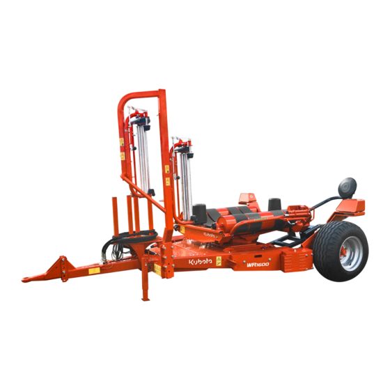
- Page 1 OPERATOR’S MANUAL WR1600 M BALE WRAPPER WR1600 C User manual Original user manual Model Year 2024 Language Document number A154224940 READ AND KEEP THE MANUAL...
-
Page 2: Machine Identification
Italy Copyright by Kverneland Group Ravenna, Italy. Reproduction, transfer to other media, translation or the use of extracts or parts of this manual without the explicit permission of Kverneland, is not permitted. All rights reserved. The contents of this operating manual are subject to change... -
Page 3: Table Of Contents
Indice del testo Preliminary operations ......Indice del testo Foreword Handling and loading instructions Abbreviations Packing and unpacking Loading and unloading Introduction ..........Preliminary checks and inspections Introduction to the manual Machine-tractor combination Reference standards Setting the height of the drawbar Symbols used Installing the hydraulic control valve cap Manufacturer and machine identification... - Page 4 Indice del testo Scheduled maintenance intervals chart Lubricant table Tightening torque table Lubrication points diagram Cleaning the machine Extraordinary maintenance Malfunction information ......Problems - Causes - Solutions General maintenance of the machine ..Reloading the film reel Reloading the “DuoWrap” film reel Adjusting the maximum pressure valve Adjusting the parallelism of the bale rotation rollers...
-
Page 5: Foreword
Keep this manual in a well-known and easily accessible place, in order to have it always at disposal when you need to read it. The Operator’s Manual must be kept in the special document compartment on the machine or in the driver’s seat of the corresponding tractor. -
Page 6: Abbreviations
Abbreviations Abbreviation Description ASABE American Society of Agricultural and Biological Engineers, USA ASTM American Society for Tasting and Materials, USA Deutsches Institut für Normung, GERMANY Feed per Minute Km/h Kilometers per Hour Meters per Second Power Take Off Revolutions per Minute Revolutions per Second Society of Automotive Engineers, USA... -
Page 7: Introduction To The Manual
(Operator's Manual and Spare Parts Manual) validated and disseminated by Kverneland Group Ravenna srl, allow for both the services required by the user and those provided under warranty to reduce the negative impact of “downtime”, to satisfy the Customers in terms of delivery speed and price/quality ratio, as well as to confirm the workshop's added value. -
Page 8: Reference Standards
For any information regarding usage or maintenance interventions not expressly indicated and/or described within this document, always standards contact exclusively the Kverneland Group Ravenna srl Service Department. Before proceeding with consultation, be sure to identify the model by using the identification plate affixed to the machine itself. -
Page 9: Symbols Used
Introduction Symbols used In order to facilitate the reading of the Operator's Manual, appropriate symbols have been included in order to highlight any warnings, risk situations, recommendations, requirements, practical advice, and simple clarifications. SAFETY FIRST This symbol, the industry’s “Safety Alert Symbol”, is used throughout this manual and on the labels affixed to the machine itself in order to warn of the possibility of personal injury. -
Page 10: Manufacturer And Machine Identification
Designation Brand Model Machine ID Type Mass Kverneland Group kg/lbs max. Hitch load kg/lbs The displayed identification plate is directly affixed to the front machine. It contains the traceability information and the references to be used when requesting technical support and/or ordering spare parts. -
Page 11: Procedure To Request Technical Assistance
Warranty As required by law, the end customer is granted a warranty period upon purchasing a new Kverneland Group brand machine. conditions The warranty’s applicability is subject to the regular performance of all the maintenance operations, based on the criteria indicated by the manufacturer. -
Page 12: Annexed Documentation
Introduction Annexed The specified documentation is supplied together with the manual and/or as an annex. documentation • Declaration of conformity • Testing certificate • Declaration of conformity with the type of machine that has been type approved for road use (only in Italy). The declaration of conformity with the approved type must be used to request certifi- cation for road use from the Traffic Control Authorities. -
Page 13: Safety Rules
Safety rules • Purpose of this This manual is intended to provide the operator with the “User Safety rules instructions” necessary to prevent and minimize the risks during manual human-machine interactions. The operator must be properly trained in order to acquire the skills necessary to carry out the work operations under safe conditions. -
Page 14: General Safety Regulations
Safety rules General safety regulations General precautions NOTICE Be sure to read the following information carefully. • Always make sure that you have fully understood the contents of the Operator’s Manual before performing any operations. DANGER Any failure to comply with procedures, recommendations, requirements, or health and safety regulations described and/or referenced (together with standards of good practice) could result in situations of risk for people, property, and the... - Page 15 Safety rules • Be sure to dedicate the necessary time to reading the instructions before using the machine or performing any maintenance operations. • Always respect the current workplace safety laws, accident- prevention regulations, and the highway code. • Pay attention to the instructional and safety labels affixed directly to the machine.
- Page 16 Safety rules signage, if necessary. NOTICE Any failure to observe the information provided could pose risks to the health and safety of individuals and could result in unforeseen expenses. • Safety regulations for The machine may ONLY travel on the road if it has been type approved in accordance with the highway code in force in the road travel country of use.
- Page 17 Safety rules • Safety regulations for The operator must read and fully understand every part of the Operator’s Manual. use and operation • The machine's operator (driver) must have the competences and skills necessary for the type of work to be carried out and must be in the appropriate conditions to perform the activity in a safe manner.
- Page 18 Safety rules • The chain must be connected to a fixed point of the tractor at a minimum height of approximately 1100 mm (43.31”) from the ground, and to the machine’s drawbar with a tension such as to guarantee that contact with the ground will be prevented, and an acceptable level of residual maneuverability for the towed machine will be ensured, in the event that the primary connection should become detached.
- Page 19 Safety rules • Do not allow any unauthorized persons (especially children, the elderly, people with disabilities, and domestic animals) to approach the operating area while the machine is in use. If necessary, stop the machine immediately and instruct the unauthorized individuals to leave the hazardous areas.
- Page 20 Safety rules • Information for the The employer must train the operator on the skills required to interact with the machine in a suitable and risk-free manner. employer • This training must be planned based on the operator's experience and in accordance with the current laws applicable at the workplace.
- Page 21 Maintenance technician specialist This is the maintenance technician of reference, a specialized technician who has been trained and qualified by Kverneland Group Srl to service the machine. The maintenance technician specialist is also the individual who performs the extraordinary maintenance or replacement operations that require an in-depth knowledge of the machine and the mechanical specifications for this type of product.
- Page 22 Safety rules Under particular environmental conditions, if you are performing the activities outside, the following equipment may be required: Reflective harness; A raincoat for bad weather; High boots for bad weather WARNING Do not wear rings, watches, jewelry, or unfastened or dangling garments, such as, for example, ties, torn garments, scarves, unbuttoned jackets, or blouses with open zippers that could get caught in moving parts.
- Page 23 Safety rules • During adjustment and maintenance operations on the machine, use proper clothing and/or the personal protective equipment specified by the manufacturer and required by the current workplace safety regulations. • ONLY replace the components with ORIGINAL spare parts or parts with IDENTICAL designs and functional features.
- Page 24 Safety rules The quick-release couplings must be closed or disconnected with caution. Any dirt or air that has entered the hydraulic system must be eliminated. Otherwise the hydraulic system could be seriously damaged. Personal injuries or property damage could occur as a result. Collect the used oil The used oil is harmful to the environment and must be collected and disposed of in compliance with the applicable national laws.
-
Page 25: Danger, Warning And Caution Labels
Safety rules Danger, warning and caution labels Decal descriptions The illustrations show the safety and information signs applied to the machine. The meaning of each signal is explained at the side. General danger: carefully read operator’s manual prior to operating the machine. - Page 26 Safety rules General danger: lifting point with fork lifting equipment. Danger of entanglement: when the motor is running, do not open or remove the guards. Danger of entanglement: when the motor is running, do not open or remove the guards. Danger of entanglement: prior to starting the machine, close the safety guards.
- Page 27 Safety rules Danger of shearing: keep your upper limbs at a safe distance from cutting elements. Danger of explosion: hydraulic accumulators contain pressurized oil and gas. Their removal or repair must be carried out in accordance with the instructions contained technical manual.
- Page 28 Safety rules Danger of body crushing: make sure that the wedges have been properly positioned prior to unhooking parking machine. Danger of body crushing: KEEP OUT of the machine's range of action when operating the rotary platform. Danger of body crushing: unload the bale in order to prevent the risk of sudden and uncontrolled...
- Page 29 Safety rules Danger of noise exposure: KEEP OUT of the film tensioning zone. If the operator is exposed to the noise for more than 4 hours a day, noise canceling headphones must worn film tensioning zone. AREA OF RISK Noisy area To avoid serious hearing injury: Stay clear of the Pre-Stretch Unit area as long as parts...
- Page 30 Safety rules CAUTION Make sure that all the decals are legible; If they are not, clean or replace them as required, and make sure that the new ones are placed in the original positions.
- Page 31 Safety rules Locations of the safety decals...
-
Page 32: Danger Zones
Safety rules Danger zones WARNING The illustration shows the danger zones where no-one should be while the machine is in use. It is the operator’s duty to keep such zones out of bounds. if necessary, he/she must turn the engine off and clear the danger zone. -
Page 33: Permissible Slopes
Safety rules Permissible slopes The illustration shows the maximum permissible slope on solid terrain, free of any uneven sections or obstacles, while the machine is running. DANGER Danger of overturning: do not use the machine on terrain whose slope exceeds the permissible limit or in the presence of other hazards (rises, hollows, etc.), which could limit the stability of the machine. -
Page 34: Signaling Devices (Only Na Markets)
Safety rules Signaling devices (only NA markets) A) “Slow-moving vehicle” sign B) Yellow reflectors C) Red reflectors • The machine is equipped with signaling devices, signs, and stickers that serve to ensure safety during road travel. The signaling devices must be in good working order at all times. The signs and stickers must not be removed. -
Page 35: Safety Devices On Board The Machine
Safety rules when circulating on the roadway, it must be removed from the tractor and placed on the dedicated support (A) on the machine itself. Safety devices on board the machine A) Rotary platform shear bolt: in the event of excessive transmis- sion stress, this bolt is sheared in order to avoid damaging the ma- chine's various assemblies and components. -
Page 36: Working At Night
Safety rules ding fork's ascent and descent speed. WARNING DO NOT tamper with or eliminate the choke screw under any circumstances. F) Pin: used to lock the loading fork in place (in its raised position) in order to prevent any sudden and dangerous movements during maintenance, road circulation, and transport operations. - Page 37 Safety rules comply with the requirements. WARNING In the case of improper machine use, the operator assumes all responsibility (moral, civil and criminal) for any resulting personal injuries and/or property damage.
-
Page 38: Residual Risks
Safety rules Residual risks Even though the manufacturer has complied with the laws in force and adopted the appropriate standards, the residual risks listed below still remain. • If the operator uses the machine at speeds that are not suitable for the ground conditions (steep terrain) and/or with slopes greater than the maximum permitted, the machine could become unstable and/or overturn. -
Page 39: General Description Of The Machine
General description of the machine • General The wrapping unit is a towed machine that has been designed and General description of the machine manufactured to wrap cylindrical bales of silage and humid description products in plastic film. All the loading, wrapping, and unloading phases are managed by an electronic control system, which is activated (in automatic or semi-automatic mode) by the driver, directly from the tractor's cab. -
Page 40: Main Components
General description of the machine Main components Control Joystick” Control “Computer” A) Drawbar: connects the machine to the tractor, and its height can be adjusted to adapt to the tractor's towing hitch. B) Loading fork: used to load the bale onto the machine's rotary platform (C). -
Page 41: Operating Cycle
General description of the machine Operating cycle The machine advances until the bale (A) is centered on the loading fork (B), which collects the bale and positions it on the rotary platform (C). The rotary platform (C) and rollers (D) will begin to turn simultane- ously in order to wrap the bale (A). -
Page 42: Equipment
General description of the machine WARNING In the case of terrain with a slope that poses a risk of sudden and uncontrolled bale movements, unload the bale perpendicular to the slope. If it is not possible to unload the bale in a safe manner, transfer the machine to a suitable area, and then unload the bale. -
Page 43: Accessories Available Upon Request
General description of the machine Accessories The machine can be equipped with certain optional accessories, either at time of order or subsequently. available upon request CAUTION Any accessories requested after the machine's purchase must be installed by personnel with specific technical skills, at a workshop that is properly equipped and authorized by the manufacturer. -
Page 44: Hydraulic Devices
General description of the machine bale wrapping times. • Tensioning unit adaptation kit: used to adapt the tensioning unit for use with 500 mm tall reels. Hydraulic devices The list only contains the descriptions and functionalities of certain hydraulic devices. A) Hydraulic cylinder: activates the loading fork's ascent and de- scent. -
Page 45: Electronic And Electrical Devices
General description of the machine Electronic and electrical devices “Computer” control “Joystick” control A) Sensor: detects the rotary platform's wrapping position. B) Sensor: detects the rotary platform's bale loading position. C) Sensor: detects the number of wraps performed and the rotary platform's bale unloading position. - Page 46 General description of the machine Page intentionally left blank...
-
Page 47: Technical Data
Technical data Technical data Technical data Description Unit of Model measurement Machine characteristics Length mm (in) 4270 (168”) Maximum pick-up width mm (in) 4240 (167”) Transport width mm (in) 2685 (106”) Maximum height mm (in) 2500 (98”) Weight kg (lb) 1920 (4233) Bale hourly output 50 - 60... - Page 48 Technical data Description Unit of Model measurement Manual loading (machines with “joystick” controls) Bale loading mode Manual, semi-automatic, automatic loading (machines with “computer” controls) Manual loading (machines with “joystick” controls) Bale unloading mode Manual, semi-automatic, automatic loading (machines with “computer” controls) Maximum platform rotation speed Tire characteristics...
-
Page 49: Technical Data Of The Electronic Control Panel
Technical data Description Unit of Model measurement Sound level detected at db(A) driver’s seat (*) Value for obtaining the platform's maximum rotation speed. Technical data of the electronic control panel Description Unit of Value measurement Display Type LCD monochrome display Size mm (inches) Display resolution... - Page 50 Technical data Page intentionally left blank...
-
Page 51: Preliminary Operations
Preliminary operations Handling and Preliminary operations loading instruc- CAUTION tions Perform the handling and loading operations in accordance with the information supplied by the manufacturer, which can be found on the machine and in the user instructions. If necessary, the individuals authorized to perform these operations must prepare a “safety plan”... - Page 52 Preliminary operations Loading the machine Proceed as indicated below. using the tractor Connect the tractor to the machine. Load the machine onto the means of transport, as shown in the figure. Use ramps with a suitable slope and load-bearing capacity. ...
-
Page 53: Preliminary Checks And Inspections
Preliminary operations Loading the machine using a hook-type WARNING lifting device Slowly lift the machine, and handle it with extreme care in order to prevent dangerous swinging motions. Proceed as indicated below. Arrange for a hook-type lifting device with a suitable lifting capacity, and connect it to the machine using appropriate chains or lifting cables. -
Page 54: Machine-Tractor Combination
Preliminary operations • Machine-tractor Upon receiving the machine, check the category and character- istics of the tractor to which it is to be coupled in order to ensure its combination stability and proper functionality. • After having verified the tractor's characteristics, the height of the drawbar must be adjusted (See “Setting the height of the drawbar”). -
Page 55: Installing The Hydraulic Control Valve Cap
Preliminary operations Installing the hydraulic control valve cap The standard hydraulic control can be transformed from an open center type to a closed center type. The transformation of the control valve from an open center type to a closed center type is recommended when connecting the machine to a tractor with a flow cancellation circuit (e.g. -
Page 56: Coupling The Machine To The Tractor
Preliminary operations Coupling the Proceed as indicated below. Upon receiving the machine, check the category and character- machine to the istics of the tractor to which it is to be coupled in order to ensure its tractor stability and proper functionality. WARNING The operations required to connect the machine to the tractor must be performed by one operator only, after having... - Page 57 Preliminary operations Connecting the hydraulic system Thoroughly clean the quick couplings. Connect the hoses (H-L) to the connectors on the tractor's control valve. NOTICE Only use original quick couplings that will ensure a proper connection. Connecting the electrical system ...
- Page 58 Preliminary operations Connecting the electronic control system Install the electronic control system (N) (complete with its support) inside the tractor's cab. The list shows the phases that are only valid for machines equipped with the “joystick” control. Connect the connector (P) to the outlet (Q). ...
-
Page 59: Computer" Control Descriptions
Preliminary operations “Computer” The list contains the description and function of each control installed on board the machine. control descrip- tions A) Electronic control system: used to program the wrapping pa- rameters. Description of the The list contains the description and function of each individual control installed on board the machine. - Page 60 Preliminary operations speed. • Control engaged in direction 1: the wrapping unit is activated (counter clockwise platform rotation). • Control engaged in direction 2: the platform is brought back to the cutting and bale unloading position (clockwise platform rotation). • Control engaged in direction 3: the bale loading fork is lowered.
-
Page 61: Description Of The "Autostop" Control Unit
Preliminary operations Description of the The list contains the description and function of each control installed on board the machine. “Autostop” control unit A) LCD Display: used to program the parameters and to display the status of the production activities. •... -
Page 62: Uncoupling The Machine From The Tractor
Preliminary operations Uncoupling the machine from the WARNING tractor Turn off the engine, engage the parking brake, and remove the ignition key. Disconnect the machine in a level and stable area that can only be accessed by authorized operators, in such a way as not to create an obstacle. - Page 63 Preliminary operations Reassemble the support foot (C) and secure it with the pin (G) and the locking pin (F). Adjust the height of the support foot (C) using the handle (D). Remove the locking pin (A) and the hitch pin (B) to disconnect the tractor from the machine.
-
Page 64: Storing The Machine At The End Of Season
Preliminary operations Storing the machine at the NOTICE end of season Before storing the machine, it is recommended to carry out a number general maintenance operations, which will help to ensure its proper functionality when the new harvest begins. Proceed as indicated below. ... -
Page 65: Putting The Machine Back Into Service
Preliminary operations Putting the machine back into NOTICE service Before using the machine after an extended period of inactivity, carefully check to make sure that its main components are working properly. In particular, carry out the following operations: Check the wear status and pressure of the tires. ... -
Page 66: Machine Demolition
Preliminary operations • Machine If necessary, the individuals responsible for carrying out the machine's demolition operations must implement a “safety plan” in demolition order to protect all the individuals directly involved, and must rigorously apply all the current safety regulations applicable to work environments and mobile work sites. - Page 67 Preliminary operations CAUTION Although the machine has been designed and manufactured to operate under harsh environmental conditions, the scheduled maintenance interventions must nevertheless be carried out regularly. Proper maintenance will ensure the machine's best possible performance, an extended service life, and constant compliance with the safety requirements. WARNING In addition to personal experience and knowledge of all the safety information, the suggestions and instructions...
-
Page 68: Indications For Producing Optimal Silage
Preliminary operations Indications for The technique of ensiling fodder in round bales wrapped mechanically with plastic film originated in northern Europe, and has become producing optimal increasingly widespread due to the numerous advantages offered with silage respect to traditional silage systems (e.g.: storage of the fodder in vertical or horizontal silos, preservation of the bales in hermetically sealed polyethylene bags, stacks of round bales covered with plastic film). - Page 69 Preliminary operations Essential character- The plastic films used to wrap round bales are polyethylene (PE) based, and are integrated with isobutyl rubber to ensure "stretch- istics of the stretch ability", as well as the copolymer ethylene vinyl acetate (EVA) to film improve their mechanical strength.
- Page 70 Preliminary operations In order to avoid the needless product losses, make sure that the humidity percentage is correct for the type of product in question prior to collecting it. 0,3-0,4 m (12”-16”) 1-1,1 m (39”-43”) THE BALE WILL BE PERFECT IF THE WINDROW IS LOW AND WIDE The best results are obtained with windrows approximately 1.10 m wide and 0.30-0.40 m high, as this will limit product losses, while at the...
- Page 71 Preliminary operations Disadvantages with high and narrow windrows • Slow advancement speed • Low degree of compression • Higher power consumption • Reduced weight • Product losses • Water penetration • Mediocre preservation • The bale could become deformed after storage Baling The bales obtained from the round balers must have a uniform density and a regular cylindrical shape, and must not contain any soil, as this...
- Page 72 Preliminary operations Incorrect advancement It should be kept in mind that the feeding always takes place in a sufficient manner at the center. If the left/right movement is too frequent, the bale will be barrel- shaped, will therefore be difficult to wrap and transport. Wide pick-up unit - advancement scheme If the machine is equipped with a wide pick-up unit, it is possible to...
- Page 73 Preliminary operations Warnings regarding the Follow the instructions and recommendations provided by the machine's manufacturer carefully, and pay particular attention to the wrapping operations points indicated below. • Make sure that the machine's maintenance is carried out correctly, with particular regard to the pre-tensioning unit, whose poor functionality could compromise the quality of the wrapped bale.
- Page 74 Preliminary operations In order to produce good silage, 4 layers of film overlap are normally sufficient, and the bale must therefore be wrapped 2 times entirely (2+2 system) (one complete turn of the bale on its axis), thus creating a high degree of resistance to the passage of air. The bale will only need to be covered with 6 layers (2+2+2 system) under particular circumstances (extreme weather conditions or long- term storage), although this method increases the possibility of air...
- Page 75 Preliminary operations 1 level less than 25% DM 2 levels 25-35% DM 3 levels over 35% DM (on the flat side) DM = % of dry material In certain cases it is preferable to store the bales on their flat side (scheme A), which has a greater number of film layers.
- Page 76 Preliminary operations Precautions WARNING The stacks of bales can be dangerous. Always keep children at a safe distance. WARNING The wrapping operations can sometimes generate high noise levels, and it is therefore recommended to use headphones for hearing protection. WARNING Follow the instructions and recommendations provided by the machine's manufacturer carefully.
-
Page 77: Preparing The Machine For Use
Preliminary operations Preparing the Before operating the machine, carry out a number of preliminary checks in order to ensure its proper performance. machine for use WARNING Stop the tractor with the engine running and engage the parking brake. Proceed as indicated below. ... -
Page 78: Changing Formats
Preliminary operations Changing formats Prior to initiating any work operations with characteristics different than the previous ones, a number of interventions must be performed upon the machine. • Positioning the bale guide cones • Changing the width of the bale loading fork •... -
Page 79: Changing The Width Of The Bale Loading Fork
Preliminary operations Changing the width of the bale WARNING loading fork Position the machine on a stable and level surface. Turn off the engine, engage the parking brake, and remove the ignition key. Proceed as indicated below. Remove the split pin (A) and extract the pin (B). ... - Page 80 Preliminary operations Changing the reel unwinding speed WARNING Position the machine on a stable and level surface. Turn off the engine, engage the parking brake, and remove the ignition key. Proceed as indicated below. Completely unscrew the knob (A) and remove the guard (B). ...
- Page 81 Preliminary operations Reel height (H) Number of teeth on the pinion (Z) No. film layers 500 mm (20”) 2+2+2 750 mm (30”) 2+2+2 Setting the film's pre- tensioning value WARNING Position the machine on a stable and level surface. Turn off the engine, engage the parking brake, and remove the ignition key.
- Page 82 Preliminary operations Pre-tensioning percentage no. gear teeth (B) no. gear teeth (C) Changing the height of the reel support WARNING Position the machine on a stable and level surface. Turn off the engine, engage the parking brake, and remove the ignition key. Proceed as indicated below.
-
Page 83: Duowrap" Work Mode
Preliminary operations “DuoWrap” work The machine can be used in both standard wrapping mode, which only uses one tensioning unit (A), and in “DuoWrap” mode, which also mode uses the second tensioning unit (B). Using the second tensioning unit as well provides for a reduction in the time necessary to completely wrap the bale, as it allows for a second layer of wrapping film to be applied simultaneously. - Page 84 Preliminary operations In order to activate “DuoWrap” mode, do the following: WARNING Position the machine on a stable and level surface. Turn off the engine, engage the parking brake, and remove the ignition key. Turn the hand wheel (A) clockwise or counter-clockwise until it reaches the end of its stroke for both directions: •...
-
Page 85: Road Travel
Preliminary operations • Road travel Road travel is only permitted for type-approved machines mounted on a tractor of an appropriate category and with suitable features. • The driver of the tractor upon which the machine is mounted must meet the requirements imposed by the current laws. CAUTION Before using the machine on public roadways, check to make sure that it is in suitable condition (unworn tires at suitable... - Page 86 Preliminary operations Page intentionally left blank...
-
Page 87: Using The Machine
Using the machine Wrapping bales Using the machine “Lever” controls WARNING Do not allow any unauthorized persons (especially children, the elderly, and domestic animals) to approach the operating area while the machine is in use. If necessary, stop the machine immediately and instruct the unauthorized individuals to leave the hazardous areas. - Page 88 Using the machine Use the lever (A) to raise the loading fork and load the bale onto the rotary platform. Use the lever (A) to lower the loading fork. Engage the lever (B) and hold it in position (for at least 2 turns of the rotary platform) in order to activate the automatic wrapping phase.
- Page 89 Using the machine Once the wrapping operation has been completed, use the lever (B) to turn the rotary platform to its unloading position. Use the lever (C) to raise the rotary platform and unload the bale onto the ground. During the unloading of the bale, the film is cut and retained by the cutting unit in order to perform the next wrapping operation.
- Page 90 Using the machine The table shows the values to be taken into account based on the dimensions of the bale and the reel, and the type of wrapping operation. No. bale No. rotary platform Reel height Bale diameter Film overlap No.
-
Page 91: Bale Wrapping ("Computer" Controls)
Using the machine Bale wrapping (“computer” controls) Introduction The “FOCUS” electronic control system has been designed and manufactured to program and control the production activities of the wrapping unit in question. The unit must be properly installed inside the tractor's cab so that the driver is able to easily program, control, and activate the various phases of the work cycle. - Page 92 Using the machine Phases of the work The list shows the sequence of the work cycle's main phases. Bale pre-loading phase: positioning of the fork with respect to the cycle ground, at the height determined by the sensor. Bale loading phase: lifting and unloading of the bale onto the platform, with the fork returning to the pre-loading position.
-
Page 93: Description Of Controls
Using the machine Description of controls PRODUCT NAME A) On/Off switch B) LCD Display C) Home screen D) Soft-key buttons programmable by the user based on the specific work requirements. E) Function or “Soft-key” buttons located next to the display. The function of each “Soft-key”... - Page 94 Using the machine “Joystick” Control The “Joystick” control disables the activation of the work cycle using the “pushbutton” controls. In conjunction with the “Work” screen, this control is used to activate the phases of the work cycle. A) Lever: a sustained-action control that can be activated on its own or else in combination with the pushbutton (B), held down.
- Page 95 Using the machine “Radio control” device (supplied upon request) The “radio control” is used to activate the bale wrapping and unloading phases from a distance. A) Pushbutton: used to turn on the device. B) Pushbutton: used to shut off the device. C) Pushbutton (sustained-action): used to raise the bale platform (inclined position).
- Page 96 Using the machine Any modifications or changes made to the device without the manufacturer's express authorization could invalidate the FCC authorization to use the device.
-
Page 97: General Description Of The Equipment
Using the machine • General The “FOCUS” electronic control system has been designed and manufactured to program and control the production activities of description of the the machine in question. equipment • The equipment must be properly installed in the cab in order to be used by the driver, who must have the necessary requirements for its safe use and operation. -
Page 98: Icon Descriptions
Using the machine 9) “Test Joystick” screen 10) “Regional Settings” screen 11) “Advanced” screen 12a)“Diagnostics 1” screen 12b)“Diagnostics 2” screen 12c)“Diagnostics 3” screen 13) “Dealer/Factory” screen 14) “Presets” screen Icon descriptions The list contains the descriptions of the icons present on the various screens, which may vary based on the wrapping unit model. - Page 99 Using the machine Icon: used to prepare the wrapping unit's operating groups for road travel. Icon: used increase RPMs programmed for the bale platform by one unit (+1). Icon: used to prepare the wrapping unit's operating groups for work mode. Icon: serves to display the “Working settings”...
- Page 100 Using the machine Icon: used to display the “ Auxiliary Settings” screen. Icon: used to display the “Regional Settings” screen. Icon: used to display the “Advanced” screen. Icons: used to display the next or previous screens. Icon: used to display the “Factory Settings” screen.
- Page 101 Using the machine Icon: indicates current automatic operating cycle. Icon: indicates that the fork is in the bale loading position. Icon: indicates that the table is in the work position. Icon: indicates that the automatic work mode is active. Icon: indicates that the semi-automatic work mode is active.
- Page 102 Using the machine Icon: used to enable the “Joystick” control's functionality. Icon: used to invert the “Joystick” control's functions. Icon: used to enable operation in “DuoWrap” mode (optional). Icon: displays the number of bales produced. Icon: displays the wrapping unit's total production counter.
-
Page 103: Parameter Programming
Using the machine Parameter programming View the desired screens (one at a time) upon which the programming or value change is to be carried out. Use the (F) buttons to select the values of the operating parameters, and press the (H) button to confirm and apply the changes. -
Page 104: Wrapping Programming
Using the machine Wrapping programming Proceed as indicated below. Access the “Presets” screen. Press one of the buttons (A-B) to view the desired wrapping program. Modify the values that do not meet the production requirements. Press the button (C) to enable the selected wrapping program. Second bale loading activation To enable the option of loading the second bale on the winter's loading... -
Page 105: Activating The Work Cycle
Using the machine On the work screen, enable the icon (B) that permits opening and lifting the fork with the second bale when strapping the previously loaded bale. Activating the Regardless of the type of control installed, the procedures listed below must be carried out in order to activate the work cycle. -
Page 106: Work Cycle With "Pushbutton" Controls
Using the machine Work cycle with “pushbutton” controls. To enable the operation of the pushbutton controls, disable the Joystick command on the “Working Settings” screen (A). A new button (B) will appear on the work screen used to access the work screen with pushbutton controls. - Page 107 Using the machine Type of functionality Work phase Manual mode (*) Semi-automatic cycle (**) Automatic cycle (**) Using the appropriate control Using the appropriate control Using the appropriate control Bale pre-loading (D), position the fork so that the (D), position the fork so that the (D), position the fork so that the bale is loaded properly.
-
Page 108: Work Cycle With "Joystick" Controls
Using the machine Work cycle with “Joystick” controls Type of functionality Work phase Manual mode (*) Semi-automatic cycle (**) Automatic cycle (**) Move the control (Q) in direction Press the control button (R). (1). Moving the control (Q) in the ... -
Page 109: Work Cycle With "Radio Control" Device
Using the machine Work cycle with “radio control” device Work phase Operating mode Bale unloading Press and hold down the (U) control. Press and hold down the (V) control to return the bale platform to its horizontal position. Bale wrapping ... -
Page 110: Resetting The Counters
Using the machine Resetting the counters Proceed as indicated below. Access the “Counter” screen. Press the button (A) to perform the reset. Equipment In the case of a generic equipment fault, the errors can be checked on the screens “Diagnostics 1 - Diagnostics 2 - functionality Diagnostics 3”. -
Page 111: Alarms List
Using the machine NOTICE In the event of a malfunction, contact the Technical Support Center authorized by the manufacturer. • Alarms list Every time the machine experiences a malfunction, an acoustic signal is emitted and an alarm message appears on the display. •... - Page 112 Using the machine Alarm description Icon Cause Solution Check the battery's charge level Tractor battery drained. and charge or replace it if necessary. 5V power supply voltage Replace the fuse or make sure Fuse damaged or disengaged. too low that it is properly inserted. Contact the Technical Support Electronic board malfunction.
- Page 113 Using the machine Alarm description Icon Cause Solution Mechanical/hydraulic problems. Contact the Technical Support Inverse table movement Table position sensor damaged. Center authorized by the too slow manufacturer. Sensor cable damaged. Position the fork manually in the Loading fork out of position. loading position.
- Page 114 Using the machine Page intentionally left blank...
-
Page 115: Maintenance And Adjustments
Maintenance and adjustments Recommenda- Maintenance and adjustments tions for WARNING adjustments Except where expressly specified, every adjustment must only be performed with the tractor's engine off, and with the ignition key removed and in the driver's possession. WARNING All personnel authorized to carry out adjustments must take all the necessary precautions to perform them correctly and in accordance with the current workplace safety regulations. -
Page 116: Recommendations For Parts Replacements
Maintenance and adjustments Recommenda- tions for parts WARNING replacements Except where expressly specified, every intervention must only be performed with the tractor's engine off, and with the ignition key removed and in the driver's possession. All personnel authorized to perform the aforementioned interventions must take the necessary precautions to ensure the safety of everyone involved, in full compliance with the current workplace health and safety requirements. -
Page 117: Lubricant Table
Maintenance and adjustments Frequency Component Type of intervention Check the wear status of the pin- Transmission chains ions and chains. Check its integrity and replace it if Shear bolt necessary. Make sure the main parts' fastening Towing drawbar and eyelet Every 50 hours screws are tightened properly. -
Page 118: Tightening Torque Table
Maintenance and adjustments Tightening torque Check all the fastening elements of the machine's various components with a torque spanner. Respect the torque values table indicated in the table.. CAUTION Replace any fastening elements that have deteriorated. NOTICE These values were obtained experimentally, and for serial applications it is recommended to check them by conducting field tests. -
Page 119: Lubrication Points Diagram
Maintenance and adjustments Lubrication points diagram WARNING Make sure the tractor's PTO is disengaged. Turn off the engine, engage the parking brake, and remove the ignition key. Lubricate the parts at the points indicated and at the intervals specified. NOTICE Before lubricating, thoroughly clean the parts involved and the greasers to prevent any impurities from mixing with the lubricant. -
Page 120: Cleaning The Machine
Maintenance and adjustments Cleaning the It is recommended to thoroughly clean the machine at the end of each work day or work shift. machine CAUTION Perform the machine cleaning operations with the engine off and under safe shutdown conditions. In order to properly clean the machine, follow the instructions below. •... -
Page 121: Malfunction Information
Malfunction information • Problems - Causes The purpose of the following information is to identify and correct Malfunction information any possible operational issues that may be encountered when - Solutions using the machine. • The various anomalies that may be encountered have been divided into tables, based on the operating group in question. - Page 122 Malfunction information Reel unwinding unit malfunctions Problem Cause Solution The rollers on the pre-tensioning Check the roller transmission's device are blocked. proper functionality. There are ripples on the pre- Use fine sandpaper to smooth the tensioning device's rollers rollers The pre-tensioning level is too high. Decrease the pre-tensioning level.
- Page 123 Malfunction information Problem Cause Solution The cutting unit does not open or Excessive friction inside the Lubricate the parts in question. opens slowly telescopic guides...
- Page 124 Malfunction information Page intentionally left blank...
-
Page 125: General Maintenance Of The Machine
General maintenance of the machine Reloading the film General maintenance of the machine reel WARNING Position the machine on a stable and level surface. Turn off the engine, engage the parking brake, and remove the ignition key. Proceed as indicated below. ... - Page 126 General maintenance of the machine Manually unwind the film from the reel, following the pathway shown in the figure, until it has arrived at the cutting unit. Tie off the end of the film and secure it to the bracket (G) so that it cannot move.
-
Page 127: Reloading The "Duowrap" Film Reel
General maintenance of the machine Reloading the “DuoWrap” film WARNING reel Position the machine on a stable and level surface. Turn off the engine, engage the parking brake, and remove the ignition key. Proceed as indicated below. Use the knob (A) to distance the unwinding roller until the stopper (C) is hooked on to the pin (B). - Page 128 General maintenance of the machine Manually unwind the film from the reel, following the pathway shown in the figure, until it has arrived at the cutting unit. Tie off the end of the film and secure it to the bracket (G) so that it cannot move.
-
Page 129: Adjusting The Maximum Pressure Valve
General maintenance of the machine Adjusting the Tecnico esperto maximum pressure valve WARNING Position the machine on a stable and level surface. Stop the tractor with the engine running and engage the parking brake. Proceed as indicated below. Use the tractor's controls to activate the hydraulic system. ... -
Page 130: Adjusting The Parallelism Of The Bale Rotation Rollers
General maintenance of the machine Adjusting the parallelism of the WARNING bale rotation Position the machine on a stable and level surface. rollers Turn off the engine, engage the parking brake, and remove the ignition key. Proceed as indicated below. ... -
Page 131: Adjusting The Tension Of The Roller Transmission Chains
General maintenance of the machine Adjusting the tension of the WARNING roller transmission Position the machine on a stable and level surface. chains Turn off the engine, engage the parking brake, and remove the ignition key. Proceed as indicated below. ... -
Page 132: Adjusting The Film Cutting Cam
General maintenance of the machine Adjusting the film Tecnico esperto cutting cam WARNING Position the machine on a stable and level surface. Stop the tractor with the engine running and engage the parking brake. NOTICE Perform the operation with a bale already loaded in order to carry out the necessary checks. - Page 133 General maintenance of the machine NOTICE Perform small movements in order to avoid botching the cam's position excessively. Tighten the screws (B). Start the tractor's engine from the driver’s seat. Perform a test wrapping phase in order to determine whether the operation has been carried out correctly.
-
Page 134: Adjusting The Film Cutting Unit
General maintenance of the machine Adjusting the film Tecnico esperto cutting unit WARNING Position the machine on a stable and level surface. Stop the tractor with the engine running and engage the parking brake. NOTICE Perform the operation with a bale already loaded in order to carry out the necessary checks. -
Page 135: Adjusting The Film Cutting Blade
General maintenance of the machine Adjusting the film Tecnico esperto cutting blade WARNING Position the machine on a stable and level surface. Stop the tractor with the engine running and engage the parking brake. NOTICE Perform the operation with a bale already loaded in order to carry out the necessary checks. -
Page 136: Adjusting The Cutting Unit's Aperture
General maintenance of the machine Adjusting the Tecnico esperto cutting unit's aperture WARNING Position the machine on a stable and level surface. Stop the tractor with the engine running and engage the parking brake. NOTICE Perform the operation with a bale already loaded in order to carry out the necessary checks. -
Page 137: Changing The Oil Filter Cartridge
General maintenance of the machine Changing the oil filter cartridge WARNING Position the machine on a stable and level surface. Turn off the engine, engage the parking brake, and remove the ignition key. Proceed as indicated below. Remove the guard (A). ... -
Page 138: Tightening The Pre-Tensioning Roller Hubs
General maintenance of the machine Tightening the pre- tensioning roller WARNING hubs Position the machine on a stable and level surface. Turn off the engine, engage the parking brake, and remove the ignition key. Proceed as indicated below. Adjust the nuts (A-B) to tighten the hubs for the pre-tensioning rollers. -
Page 139: Cutting Unit Cylinder Pressure Recharging Mode(S)
General maintenance of the machine Cutting unit cylinder pressure WARNING recharging Position the machine on a stable and level surface. mode(s) Turn off the engine, engage the parking brake, and remove the ignition key. Proceed as indicated below. Unscrew the cap (A). ... -
Page 140: Replacing The Tires
General maintenance of the machine Replacing the tires WARNING Position the machine on a stable and level surface. Turn off the engine, engage the parking brake, and remove the ignition key. WARNING The tire replacement operations can pose certain risks, above all considering the overall weight of the machine. - Page 141 General maintenance of the machine 310 Nn 230 ft.lbs Reinstall the wheel and tighten the nuts in a symmetrical manner. Tighten the nuts to the correct torque value. Lower the machine, and fully tighten the nuts (B). Inflate the tire to the pressure value indicated in the table. ...
-
Page 142: Replacement Of The Shear Bolt
General maintenance of the machine Replacement of the shear bolt WARNING Position the machine on a stable and level surface. Turn off the engine, engage the parking brake, and remove the ignition key. Proceed as indicated below. Unscrew the knob and remove the guard (A). ... -
Page 143: Replacing The Film Cutting Blade
General maintenance of the machine Replacing the film cutting blade WARNING Position the machine on a stable and level surface. Stop the tractor with the engine running and engage the parking brake. Proceed as indicated below. Use the machine's controls to open the cutting device. CAUTION Wear protective gloves in order to avoid the risk of cutting your hands. - Page 144 General maintenance of the machine Page intentionally left blank...
-
Page 145: A01 - Wiring Diagrams
A01 - Wiring diagrams A01 - Wiring diagrams Page intentionally left blank... - Page 146 A01 - Wiring diagrams ESD A01 - AUTOSTOP CONTROL UNIT WIRING DIAGRAM Electrical system components Code Figure Designation Photogra reference ph No. Autostop Control Unit CAN power cable Signal cable Power cable Signal cable M18 sensor PBA + A01 + A04 Complete Autostop Control Unit PBA + A01 + A02 + Complete Autostop control unit system...
- Page 147 A01 - Wiring diagrams...
- Page 148 A01 - Wiring diagrams Page intentionally left blank...
- Page 149 A01 - Wiring diagrams ESD A02 - WIRING DIAGRAM WITH “COMPUTER” CONTROLS Electrical system components Code Figure Designation Photogra reference ph No. Control unit Control unit Data connection cable Table position sensor cable Table lifting valve cable Table lowering valve cable Proportional valve Joystick PCEU...
- Page 150 A01 - Wiring diagrams Code Figure Designation Photogra reference ph No. Remote control receiver Remove control charge cable...
- Page 151 A01 - Wiring diagrams length A136172100 order information (mm) A136172100 BB WRAPPER TURNTABLE SGE CABLE CAN 6000 SENSOR CABLE ROTATION/TABLE TIP 3000 CABLE TABLE UP 1000 CABLE TABLE DOWN 1000 PROPORTIONAL VALVE 1000 PILOTBOX FOCUS 3 CLAMP SET RAM 1INCH MNT PILOTBOX JOYSTICK SWITCH 1X CABLE GLAND NUT M20 1X SENSOR PROX M18 S...
- Page 152 A01 - Wiring diagrams ESD A03 - PERFORATION SCHEME FOR “CONTROL UNIT” (ECU) table cable CAN loading table down rotation arm in pulses ECU_PWR ECU_GND transport remote control ECU_PWR ECU_GND DIAG arm up arm down P W R down G N D O N _ S W D I _ table...
- Page 153 A01 - Wiring diagrams ESD A04 - WIRING DIAGRAM AND DECAL FOR "CONTROL UNIT” rf table down rf table up table rf stop loading pos table down rf start arm in rf power transport arm down oscill. sensor ECU_PWR ECU_GND ECU_PWR ECU_GND DIAG...
- Page 154 A01 - Wiring diagrams ESD A05 - AUTOSTOP CONTROL UNIT SIGNAL CABLE WIRING DIAGRAM...
- Page 155 A01 - Wiring diagrams ESD A06 - AUTOSTOP CONTROL UNIT POWER CABLE WIRING DIAGRAM...
- Page 156 A01 - Wiring diagrams ESD A07 - POWER CABLE WIRING DIAGRAM...
- Page 157 A01 - Wiring diagrams ESD A08 - SIGNAL CABLE WIRING DIAGRAM...
- Page 158 A01 - Wiring diagrams Page intentionally left blank...
-
Page 159: A02 - Hydraulic Diagrams
A02 - Hydraulic diagrams HSD A00 - HYDRAULIC SYSTEM A02 - Hydraulic diagrams Table of contents for hydraulic system Reference Figure Designation reference HSD A01 Hydraulic system diagram with “computer” controls A+B+C+G+F+D HSD A02 Hydraulic system diagram with “lever” controls Hydraulic control valve for “lever”... - Page 160 A02 - Hydraulic diagrams HSD A01 - HYDRAULIC SYSTEM DIAGRAM WITH “COMPUTER” CONTROLS Hydraulic system components Reference Technical data Designation Bale loading fork hydraulic control cylinder Check valve Platform tipping hydraulic control cylinder Ø 1.25 mm One-way throttle Ø 1 mm One-way throttle Hydraulic platform rotation motor Electro-hydraulic motor control block...
- Page 161 A02 - Hydraulic diagrams...
- Page 162 A02 - Hydraulic diagrams HSD A02 - HYDRAULIC SYSTEM DIAGRAM WITH “LEVER” CONTROLS Hydraulic system components Reference Code Technical Designation data 8859916 Bale loading fork hydraulic control cylinder 8859720 Platform tipping hydraulic control cylinder 3311500 Ø 1.25 mm One-way throttle 3411700 Ø...
- Page 163 A02 - Hydraulic diagrams...
- Page 164 A02 - Hydraulic diagrams HSD A04 - CUTTING UNIT HYDRAULIC SYSTEM DIAGRAM Hydraulic system components Reference Technical data Designation Cutting unit hydraulic control cylinder Accumulator Cutting unit control valve Hydraulic pump 70 bar Maximum pressure valve Oil filter...
- Page 165 A02 - Hydraulic diagrams...
- Page 166 A02 - Hydraulic diagrams HSD A05 - HYDRAULIC CONTROL VALVE FOR “LEVER” CONTROLS...
- Page 167 A02 - Hydraulic diagrams HSD A07 - HYDRAULIC CONTROL VALVE FOR “COMPUTER” CONTROLS...
- Page 168 A02 - Hydraulic diagrams Page intentionally left blank...
-
Page 169: Indice
Indice “Computer” control descriptions Indice “DuoWrap” work mode Electronic and electrical devices “Joystick” Control Equipment “Lever” controls Equipment functionality troubleshooting “Radio control” device (supplied upon request) Essential characteristics of the stretch film Extraordinary maintenance Accessories available upon request Activating the work cycle General description Adjusting the cutting unit's aperture General description of the equipment... - Page 170 Indice Safety rules for the protection of the environment 24 Scheduled maintenance intervals chart Norme di consultazione Second bale loading activation Notes on the remote control for the USA and Canada Setting the film's pre-tensioning value Setting the height of the drawbar Signaling devices (only NA markets) Simbologia utilizzata Storage of the film reels...
Need help?
Do you have a question about the Kubota WR1600 M and is the answer not in the manual?
Questions and answers