Table of Contents
Advertisement
Quick Links
Advertisement
Table of Contents

Related Manuals for SMC Networks 7824M/VSW


Summary of Contents for SMC Networks 7824M/VSW
- Page 2 Information furnished by SMC Networks, Inc. (SMC) is believed to be accurate and reliable. However, no responsibility is assumed by SMC for its use, nor for any infringements of patents or other rights of third parties which may result from its use. No license is granted by implication or otherwise under any patent or patent rights of SMC.
- Page 3 Installation Manual TigerAccess™ EE Warranty and Product Registration To register SMC products and to review the detailed warranty statement, please refer to the Support Section of the SMC Website at http://www.smc.com SMC7824M/VSW...
- Page 4 Installation Manual TigerAccess™ EE Reason for Update Summary: Initial release Details: Chapter/Section Reason for Update Initial release Issue History Issue Date of Issue Reason for Update Number 05/2009 Initial release SMC7824M/VSW...
-
Page 5: Table Of Contents
Installation Manual TigerAccess™ EE Contents Protective Measures ................... 7 General Notes..................... 7 Protection against Excessive High Contact Voltage........... 8 Protection against Escaping Laser Light ............8 Protection against Fire in Racks or Housings ............ 9 Components Subject to Electrostatic Discharge ..........9 Handling Modules (General)................ - Page 6 Installation Manual TigerAccess™ EE Illustrations Fig. 1.1 Laser Symbol ....................8 Fig. 2.1 Product View ....................12 Fig. 2.2 Front Interfaces of the switch .................13 Fig. 2.3 LEDs of the Switch ..................16 Fig. 2.4 LEDs of the Option Uplink Modules ...............18 Fig. 3.1 Grounding Symbol..................19 Fig.
- Page 7 Installation Manual TigerAccess™ EE Tables Tab. 2.1 Front Access Interfaces of the switch............13 Tab. 2.2 Operating Status LEDs on the switch............16 Tab. 2.3 Status LEDs for VDSL Interfaces ..............17 Tab. 2.4 Status LEDs on Console Interface ..............17 Tab.
-
Page 8: Protective Measures
Installation Manual TigerAccess™ EE 1 Protective Measures This section includes the following topics: General Notes • Protection against Excessive High Contact Voltage • Protection against Escaping Laser Light • Protection against Fire in Racks or Housings • • Components Subject to Electrostatic Discharge Handling Modules (General) •... -
Page 9: Protection Against Excessive High Contact Voltage
Installation Manual TigerAccess™ EE Protection against Excessive High Contact Voltage When dealing with the power supply or working on it, observe the provisions of VDE 0105 (operation of high-voltage equipment) Part 1, Section 9.3 (safety measures to be carried out) and the specifications of the European Norm EN 50110, Part 1 and Part 2 (Operation of electrical systems) at all times. -
Page 10: Protection Against Fire In Racks Or Housings
Installation Manual TigerAccess™ EE Protection against Fire in Racks or Housings If the system is used in housing, the system must comply with the conditions for fire pro- tection housing according to DIN EN 60950-1. To comply with fire protection standards as defined in DIN EN 60950-1, a protective plate (C42165-A320-C684) must be fitted into the floor of ETSI and 19-inch standard racks. -
Page 11: Handling Optical Connectors And Fiber Optic Lines
Installation Manual TigerAccess™ EE There is a danger of injury if the door is left open. When inserting and removing shelves and when transporting them, take their weight • into consideration. Cables may never be disconnected by pulling on the cable. Disconnec- •... -
Page 12: Ul Safety Compliance
RoHS. SMC Networks reserves the right to apply the exemptions to the RoHS requirements as set out in the Annex to the RoHS directive, in particular lead in solders for network infra- structure equipment for switching, signaling, transmission as well as network manage- ment for telecommunication. -
Page 13: Overview
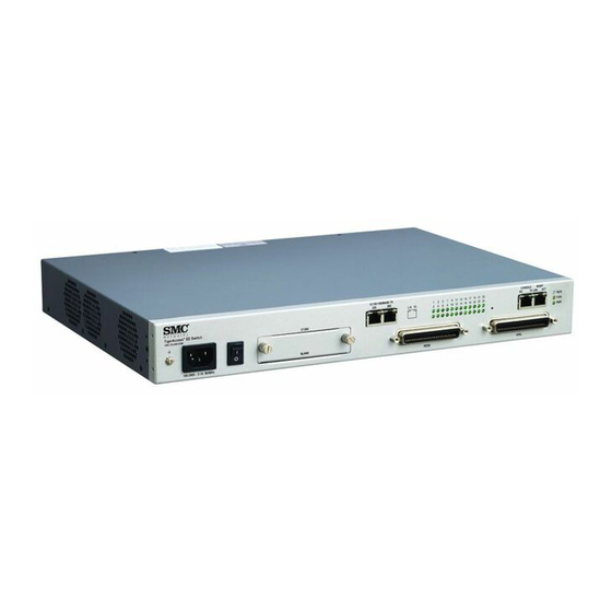
Installation Manual TigerAccess™ EE 2 Overview SMC7824M/VSW is a 1.25U height single-board IP-DSLAM. It has been designed as compact-sized customer premise equipment for VDSL2 networks. The switch offers 24-Port VDSL2 service interface and fixed 2-Port 10/100/1000Base-T and 1-slot for option uplink module. The option module for uplink interface is also availale. NOTE –... -
Page 14: Product Specification
Installation Manual TigerAccess™ EE The interfaces of the switch are to find in Fig. 2.2 Tab. 2.1. Console GTX Uplink Ports LEDs of VDSL i/f MGMT Access VDSL/POTS (1-24) Optional Expansion Slots System LED Front Interfaces of the switch Fig. 2.2 Name Function Connector Type... -
Page 15: Functionalities
Installation Manual TigerAccess™ EE 2.1.2 Functionalities The switch provides the following functionalities: Advanced VDSL2 Function Configuration of xDSL line rate • Provision of different band plans and profiles for xDSL interfaces • • VDSL2 interface according to ITU-T G.993.2 Band plans 997, 998 and profiles 8a, 8b, 12a, 12b and 17a configurable per port •... -
Page 16: Physical Specification
Installation Manual TigerAccess™ EE Security 802.1x MAC/port based authentication • Storm control for broadcast, multicast and unknown unicast packets • • DoS protection Outband management • • IP source guard Secure Shell (SSH) • Management Serial/Telnet (CLI) • • SNMPv1/v2/v3 Single IP management •... -
Page 17: Operating Status Leds
Installation Manual TigerAccess™ EE Power Supply AC power voltage 100-240VAC, 50/60Hz Maximum power consumption 85W (with 2-Port SFP option module) 88W (with 1-Port GE-PON + 1-Port SFP option module) Operating Indicators System LEDs RUN / FAN / PWR VDSL i/f LEDs Uplink i/f LEDs L/A, 1G (1000Base-X, SFP) LNK (GE-PON) - Page 18 Installation Manual TigerAccess™ EE Status LEDs for VDSL Interfaces Label Color Status Description 1-24 Green The interface is connected to a CPE. Blinking The interface is starting to be connected to a CPE. The interface is not connected to a CPE. Status LEDs for VDSL Interfaces Tab.
-
Page 19: Items Supplied
Installation Manual TigerAccess™ EE LEDs of the Option Uplink Modules Fig. 2.4 Status LEDs for Uplink Interfaces Label Color Status Description Green On/Blinking The interface is connected to a network. The interface is not connected to a network. Amber The transmit rate is 1 Gbps. The transmit rate is not 1 Gbps. -
Page 20: Setting Up The Rack
Installation Manual TigerAccess™ EE 3 Setting Up the Rack When setting up the rack, you must first install the rack and then the system. Refer to the assembly documents. Rack Installation The switch is designed for indoor operation in the central office or collocation room with controlled environmental conditions. -
Page 21: Fig. 3.2 19" Rack (Sectional View)
Installation Manual TigerAccess™ EE After the rack has been constructed, you can equip it. 19” Rack (Sectional View) Fig. 3.2 465.1 19” Rack (Front View) Fig. 3.3 SMC7824M/VSW... -
Page 22: Installing The System
Installation Manual TigerAccess™ EE Installing the System 3.3.1 Equipping the Rack 1. Attach the rack brackets to the edge sides of the system as Fig. 3.4. Attaching the Rack Brackets Fig. 3.4 2. Attach the system by inserting the cage nuts in the rack uprights in accordance with your rack configuring plan. -
Page 23: Mounting On A Wall
Installation Manual TigerAccess™ EE For equipping the system in ETSI rack, use the ETSI rack mount kit. 3.3.2 Mounting on a Wall You can use the wall mounting brackets for mounting the switch on a wall. To mount the switch on a wall, follow these steps: 1. -
Page 24: Fig. 3.7 The Switch Mounted On A Wall
Installation Manual TigerAccess™ EE The switch mounted on a wall Fig. 3.7 SMC7824M/VSW... -
Page 25: Grounding The System
Installation Manual TigerAccess™ EE 3.3.3 Grounding the System The system must always be grounded. Following grounding method is used for the switch: In a rack, as the only installation variant, the switch is grounded by screw con- • nection with the grounded rack. Pay attention to strong screw connections. The system should be grounded with permanent connection to the protective earthing terminal. -
Page 26: Equipping The System
Installation Manual TigerAccess™ EE 4 Equipping the System Installing Uplink Module The switch provides the reserved slot for the uplink option module. The system will be de- livered without the option module. When installing the uplink option module, note the followings: When inserting the option module, observe the ESD requirements for protecting the •... -
Page 27: Cabling The System
Installation Manual TigerAccess™ EE 5 Cabling the System Complete the following connections: Connecting Uplink Interface Connecting VDSL Interface Connecting Console Access Connecting MGMT Interface Connecting Power Supply Use the cable sets appropriate to your application, and consult your cabling plan for the required cable types for the various connecting cables: Category 5 Ethernet UTP cable •... -
Page 28: Connecting Uplink Interface
Installation Manual TigerAccess™ EE Connecting Uplink Interface 5.1.1 Installing Optical Connection The switch provides uplink 1-slot which requires its own additional optical module. You can select the proper module in Tab. 6.3. In this section, the case of installing an optical connection with the LC type SFP module is described. -
Page 29: Installing Ge-Pon Connection
Installation Manual TigerAccess™ EE 5.1.2 Installing GE-PON Connection The switch provides 1-slot for an uplink module which has 1-port of 1000Base-X and 1- port of GE-PON interface. Use the following procedure when installing the GE-PON con- nection on uplink modular unit. 1. -
Page 30: Installing Electrical Connection
Installation Manual TigerAccess™ EE 5.1.3 Installing Electrical Connection According to the network or installation environment, you can use 10/100/1000Base-T in- terface instead of the optical connection. The switch automatically recognizes MDI/MDIX connectors defined in IEEE 802.3. RJ45 Connector Fig. 5.3 Use the following procedure when installing an electrical connection. -
Page 31: Connecting Vdsl Interface
Installation Manual TigerAccess™ EE Connecting VDSL Interface The switch provides 24 VDSL ports as a subscriber interface. To enable broadband ser- vices to the subscriber, connect the copper cable to the Main Distribution Frame (MDF). 5.2.1 Connecting the System to the Main Distribution Frame Use this procedure when installing VDSL connections between the system and the MDF. -
Page 32: Connecting Narrowband Services
Installation Manual TigerAccess™ EE 5.2.2 Connecting Narrowband Services Use this procedure when connecting narrowband services. 1. Cut the cables to length. 2. Attach the connectors to the cables. 3. Label and mark the cables. 4. Install the cables to the POTS interfaces on the front panel of the switch in ac- cordance with your cabling plan. -
Page 33: Connecting Console Access
Installation Manual TigerAccess™ EE Connecting Console Access The switch provides the console access to configure the system locally with command line interface (CLI). The RJ45-to-DB9 console cable will be delivered as a basic delivery package. 1. Connect DB9 connector of the supplied RJ45-to-DB9 console cable to the serial in- terface of the PC. -
Page 34: Connecting Mgmt Interface
Installation Manual TigerAccess™ EE Connecting MGMT Interface Use this procedure when connecting the 100Base-T outband MGMT interface. 1. Cut the cables to length. 2. Attach the RJ45 connector to the cable. 3. Label and mark the cables. 4. Route and stow the cable with the RJ45 connector in the rack. 5. -
Page 35: Connecting Power Supply
Installation Manual TigerAccess™ EE Connecting Power Supply To connect the operating voltage line to AC power supply and to the system: 1. Connect the provided AC power cable to AC power connector on the front panel of the switch. 2. Connect the other end of the power cable to AC power supply. Fig. -
Page 36: Appendix
Installation Manual TigerAccess™ EE 6 Appendix Abbreviations Communauté européenne, European Community Customer Premises Equipment DSLAM Digital Subscriber Line Access Multiplexer European Norm ETSI European Telecommunications Standards Institute Fast Ethernet (100 Mbps) Gigabit Ethernet (1 Gbps) International Electrotechnical Commission IEEE Institute of Electrical and Electronic Engineers Internet Protocol Light Emitting Diode Main Distribution Frame... -
Page 37: A2 Ordering Information
-. Fixed 2-Port 10/100/1000Base-Tx uplink & 1-slot option module -. 600 Ohm POTS Splitter without billing tone. -. Fan : Fixed Type -. Front access with 1.25U height -. UL certification product -. SMC specific product / Silk: SMC Base Options Tab. 6.1 CPE options Name... - Page 38 Installation Manual TigerAccess™ EE SMC7824M/VSW...
- Page 39 Fax (65) 6 238 6466 Korea: 82-2-553-0860; Fax 82-2-553-7202 Japan: 81-45-224-2332; Fax 81-45-224-2331 Australia: 61-2-8875-7887; Fax 61-2-8875-7777 India: 91-22-8204437; Fax 91-22-8204443 If you are looking for further contact information, please visit www.smc.com, www.smc- europe.com, or www.smc-asia.com. 20 Mason Irvine, CA 92618 Phone: (949) 679-8000...
Need help?
Do you have a question about the 7824M/VSW and is the answer not in the manual?
Questions and answers