
Related Manuals for Omtech USB1410a


Summary of Contents for Omtech USB1410a
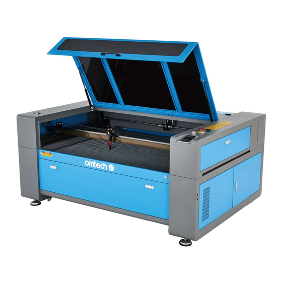
- Page 1 V20230802 USB1410a Cabinet Laser Engraver User Manual Read Carefully Before Use Keep for Future Reference...
- Page 2 PREFACE Thank you for choosing our laser equipment. Your CO laser engraving machine is intended for personal and professional use. When used in accordance with these instructions, it comprises a Class 1 laser system but some components remain EXTREMELY dangerous. Never disable the preinstalled safety devices and always use your laser safely and responsibly.
-
Page 3: Table Of Contents
CONTENTS 1. Introduction ................................1 1.1 General Information ............................1 1.2 Symbol Guide ..............................2 1.3 Designated Use ...............................2 1.4 Technical Specifi cations ..........................3 1.5 Components ..............................4 2. Safety Information ...............................10 2.1 Disclaimer ..............................10 2.2 General Safety ...............................10 2.3 Laser Safety ..............................11 2.4 Electrical Safety ............................12 2.5 Material Safety ..............................12 3. - Page 4 4.4.6 Flash Drive Commands ........................27 4.4.7 Adjusting Engraving Layers ........................27 4.4.8 Function Menu .............................28 4.4.9 Adjusting the Z Axis ..........................28 4.4.10 Setting an Interface Password ......................28 4.4.11 Manual Movement of the Laser Head ....................29 4.4.12 Manual Firing of the Laser ........................29 4.4.13 Setting Origin Points ..........................30 4.4.14 Saving Current Parameters and Virtual Keyboard Use ..............31 4.4.15 Loading Saved Parameters .........................31...
-
Page 5: Introduction
1. Introduction 1.1 General Information This manual is the designated user guide for the installation, setup, safe operation, and maintenance of your cabinet laser engraver. It is divided into six chapters covering general information, safety instructions, installation steps, operation instructions, maintenance procedures, and contact information. ALL personnel involved in the installation, setup, operation, maintenance, and repair of this machine should read and understand this manual, particularly its safety instructions. -
Page 6: Symbol Guide
1.2 Symbol Guide The following symbols are used on this machine’s labeling or in this manual: These items present a risk of serious property damage or personal injury. These items address similarly serious concerns with regard to the laser beam. These items address similarly serious concerns with regard to electrical components. -
Page 7: Technical Specifi Cations
1.4 Technical Specifi cations Model USB1410a Diameter 2.76 in. 70 mm Laser Tube Length 69.96 in. 1650 mm Diameter 0.79 in. 20 mm Focus Lens Thickness 0.08 in. 2 mm Focal Length 2.5 in. 63.5 mm Diameter 0.98 in. 25 mm... -
Page 8: Components
1.5 Components... -
Page 9: Main Parts
Main Parts A. Cover—The cover provides access to the main bay for placing and retrieving materials, as well as fi xing the laser path alignment and other maintenance. Power to the laser is automatically cut when the cover is opened. B. -
Page 10: Laser Head
Laser Path A. Laser Tube—This CO₂-fi lled glass tube is mounted on brackets and immobile. Its connection to the laser power supply is extremely high voltage and extremely dangerous. B. 1st Mirror—This adjustable-angle mirror is fi xed in place to transfer the engraving laser from the tube to the 2nd mirror. - Page 11 Connection Inputs A. USB Port—This port allows you to load and save designs and parameters directly onto the engraver. B. USB Line Port—This port connects to your control computer and its engraving software using any of its USB ports. C. Ethernet Port—This port connects to your control computer and its software either directly or via the internet.
-
Page 12: Control Console
Control Console Returns the machine to the saved default Stops work or returns to a previous menu parameters (See §4.4.14) Enters a command or confi rms your Stops the current job selection Sets the starting point for the laser head Opens the Main menu (See §4.4.2) (See §4.4.13) Traces the outline of the current design... -
Page 13: Console Screen
Console Screen A. Design Display: shows the whole fi le’s track and the running track. B. Parameters: displays the running fi le’s fi le number, speed, max power, etc. C. Coordinates: displays the current coordinates of the laser head. D. Layers: displays the layer parameters of current or previewed fi les. Parameters from left to right are layer number, color, speed, and maximum power. -
Page 14: Safety Information
2. Safety Information 2.1 Disclaimer Your engraver may diff er somewhat from those shown in this manual due to options, updates, etc. Please contact us if your engraving machine came with an outdated manual or if you have any other questions. 2.2 General Safety Instructions •... -
Page 15: Laser Safety
2.3 Laser Safety Instructions When used as instructed, this machine comprises a Class 1 laser system safe for users and bystanders. However the invisible engraving laser, the laser tube, and its electrical connections remain EXTREMELY dangerous. Used or modifi ed without care, they can cause serious property damage and personal injury including but not limited to the following: •... -
Page 16: Electrical Safety
2.4 Electrical Safety Instructions • ONLY use this device with a compatible and stable power supply with less than 5% fl uctuation in its voltage. • DO NOT connect other devices to the same fuse, as the laser system will require its full amperage. Do not use with standard extension cords or power strips. - Page 17 This machine can be safely used with the following materials: Plastics • Acrylonitrile Butadiene Styrene (ABS) • Nylon (Polyamide, PA, etc.) • Polyethylene (PE) • High-Density Polyethylene (HDPE, PEHD, etc.) • Biaxially-Oriented Polyethylene Terephthalate (BoPET, Mylar, Polyester, etc.) • Polyethylene Terephthalate Glycol (PETG, PET-G, etc.) •...
-
Page 18: Installation
3. Installation 3.1 Installation Overview A complete working system consists of the laser engraving cabinet, its vents, all applicable connection cables, and the laser and access keys. The cabinet can use designs provided by the enclosed engraving software by direct or internet connection with your computer;... -
Page 19: Electrical Grounding
Step 3. CAREFULLY remove the rest of the foam packaging material from around the laser tube, the viewing window, and the rest of the machine. The laser tube is a highly fragile object and should be handled delicately and as little as possible. Step 4. -
Page 20: Water Cooling Installation
3.5 Water Cooling Installation Using a water chiller (not incl.) is essential to your engraver’s performance and longevity. When this laser works without a properly maintained cooling system, its glass tube WILL explode from excess heat. NEVER touch or adjust your engraver's water supply while the pump is connected to power. To install your pump, fi... -
Page 21: Exhaust System
3.6 Exhaust System Install the provided exhaust pipes directly onto the fans. The pipes can be expanded to a full length of about 5 feet (1.5 m). The other end should be connected to a dedicated purifi er or (if the fumes are not hazardous and meet local and national air safety standards) placed out a window. -
Page 22: Initial Testing
3.9 Initial Testing Emergency Shutoff Because of the risk of fi re and other hazards during engraving, this engraver includes a large and easy-to-reach emergency stop button near the control panel. Press it down to stop the laser tube instantly. When your engraver arrives, its e-stop is already pressed and must be pulled up to allow the laser to function. -
Page 23: Air Assist
Water Shutoff Because of the danger posed by an uncooled laser tube, this engraver also shuts off the laser automatically when the water cooling system malfunctions. After ensuring that the emergency stop button and cover protection both work, you should also test that the water shutoff... -
Page 24: Operation
4. Operation 4.1 Operation Overview Operate this laser marking machine only in accordance with all the instructions provided in this manual. Failure to follow the proper guidelines detailed here can result in property damage and personal injury. This section will address only some of the options and features provided by the operation software. Before beginning to use the machine, make sure that you have read this entire manual (particularly the Safety Information above), the separate software manual, and any and all warnings provided on the machine itself. -
Page 25: Instructions For Specifi C Materials
Power (%) Current (mA) 7–8 12–14 18–19 22–23 24–26 30–31 32–33 The threshold for the lowest setting is 10%. The laser will not fi re at any setting lower than this. It is NOT recommended to use the laser tube at full capacity, especially for extended periods. The recommended maximum power setting is 70%, as prolonged use above that amount will shorten your laser's service life. - Page 26 Ceramics When engraving on ceramics, generally use moderate to high power. Using more loops rather than higher power and lower speed can help avoid cracking the material during work. Be mindful of the health risk posed by dust generated from ceramic engraving, especially for repetitive industrial applications. Depending on the material and the amount of work, a fan or even full ventilation system may be required to address the problem.
- Page 27 Average Cutting Settings for Acrylic Thickness of Acrylic Description ¹/₁₆ in. ⅛ in. ¼ in. ½ in. ¾ in. 1 in. 1⅛ in. Power 130W Speed 30 mm/s 15 mm/s 7 mm/s 6 mm/s 5 mm/s 2 mm/s 1 mm/s Rubber The various compositions and densities of rubber cause slightly varying engraving depth.
-
Page 28: Control Console
4.4 Control Console Instructions 4.4.1 Overview You can control your engraver directly from the built-in control panel, through a direct connection with your computer, or over the internet. For details on operating your engraving software, see its separate manual. The built- in control panel can operate the laser manually or engrave designs loaded onto fl... -
Page 29: Menu Button
4.4.2 Menu Button Press MENU on the main interface to enter the Menu interface: Push the ▲ and ▼ keys to select items, and then press ENTER to enter the corresponding submenu. 4.4.3 Setting the Laser Speed Select "Speed" on the Menu interface, and the following dialogue box will appear: The cursor will appear when pushing the ◄... -
Page 30: File Commands
4.4.5 File Commands Select "File" on the Menu interface, and the following dialogue box will appear: When entering the above interface, the system automatically reads the memory fi les. The fi le name and the work times will be listed, and the selected fi le will be previewed in the upper right corner. When there are several fi les, use the ▲... -
Page 31: Flash Drive Commands
4.4.6 Flash Drive Commands Select "U-disk" on the File interface and press ENTER, and the following dialogue box will appear: The operation method is the same as that of fi les in memory. Press ESC to return to the File interface. •... -
Page 32: Function Menu
4.4.8 Function Menu Press FN on the main interface to enter the following menu: Push the ▲ and ▼ keys to move the light blue cursor to the intended entry, and press ENTER to enter the corresponding submenu. 4.4.9 Adjusting the Z Axis When the light blue cursor is on "Z move", push the ◄... -
Page 33: Manual Movement Of The Laser Head
4.4.11 Manual Movement of the Laser Head When the light blue cursor is on "Manual Set+", press ENTER, and the following dialogue box will pop up: When the light blue cursor is on "Mode", push the ◄ and ► keys to choose between the two modes "Continue" and "Manual". -
Page 34: Setting Origin Points
4.4.13 Setting Origin Points When the light blue cursor is on "Origin Set+", press ENTER, and the following dialogue box will pop up: Press FN to move the light blue cursor to an item and press ENTER to enable or disable the item. When enabled, the small box will be red and, when disabled, the small box will be gray. -
Page 35: Saving Current Parameters And Virtual Keyboard Use
4.4.14 Saving Current Parameters and Virtual Keyboard Use When the light blue cursor is on the "Set Fact Para" item, press ENTER, and the following dialogue box will pop up: The password consists of six characters. Push the ▲ and ▼ and ◄ and ► keys to select each character, and press ENTER to confi... -
Page 36: Setting The Machine's Ip Address
4.4.18 Setting the Machine's IP Address When the light blue cursor is on this item, press ENTER, and the following dialogue box will pop up: Press FN to move the light blue cursor to the intended item, and push the ▲ and ▼ and ◄ and ► keys to change the parameters. -
Page 37: Resetting Axes
4.4.21 Resetting Axes When the green block is on this item, press ENTER, and the following dialogue box will pop up: Push the ▲ and ▼ keys to move the light blue block to the intended item. Press ENTER to start the resetting of the selected axis. -
Page 38: Maintenance
The whole laser machine including the other components such as the water cooling system must be checked every month and cleaned where required. For video instructions on general maintenance, see our YouTube channel’s guide “OMTech Training—Cleaning Your CO Laser Engraver.”... -
Page 39: Main Bay & Engraver
If the water remains visibly clean at all times, it is still recommended that you clean the water tank about once a month as a precaution, changing the water as you do so. If you use an industrial water chiller instead of the provided pump, follow its separate instructions for maintenance but similarly ensure that the water used remains cool, clean, and pure. - Page 40 4. Remove the pressurized air hose and laser guide connections. 5. Once positioned over your clean lens-cleaning tissue, remove the lens from the lens holder by carefully turning the lens holder and letting the lens and its O-ring drop onto the cleaning cloth. 6.
-
Page 41: Mirrors
5.3.4 Cleaning the Mirrors The mirrors should be similarly cleaned if there is any debris or haze on their surface to improve performance and avoid permanent damage. The 1st mirror is located in the back left of the machine beyond the far end of the Y axis. The end of the laser tube closest to this mirror is itself a semitransparent mirror that should be checked at the same time. -
Page 42: Laser Tube
5.4.1 Red Dot Locator Alignment To test the alignment of the laser tube with the 1st mirror, cut out a piece of tape and place it on the mirror's frame. DO NOT place the tape directly onto the mirror. Turn on the machine and set the power level to 15% or lower. Press PULSE to manually fi... -
Page 43: First Mirror
5.4.2 1st Mirror Alignment After ensuring the laser is well aligned between the laser tube and 1st mirror, check the alignment between the 1st and 2nd mirrors. First, use the direction arrows on the control panel to send the 2nd mirror to the back of the bed along the Y axis. -
Page 44: Second Mirror
5.4.3 2nd Mirror Alignment After ensuring the laser is well aligned between the 1st and 2nd mirrors, check the alignment between the 2nd and 3rd mirrors. Repeat the steps and adjustments above, taking care to use the tape on the mirror's frame and not its surface. -
Page 45: Parts Replacement
QR code to the right. Come join the OMTech community at our official laser group on Facebook or visit the company forums at omtechlaser.com! Check our YouTube channel for helpful hints and instructional videos. - Page 46 U S B - 1 4 0 9 - U S Rev. 2 Aug. 2023...
Need help?
Do you have a question about the USB1410a and is the answer not in the manual?
Questions and answers