
Related Manuals for Omtech USB 460k


Summary of Contents for Omtech USB 460k
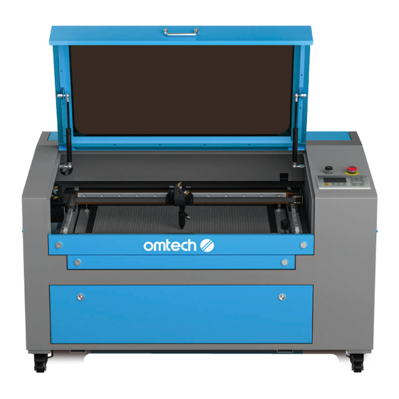
- Page 1 V20241216 USB 460k | 60W | CO Cabinet Laser Engraver User Manual Read Carefully Before Use Keep for Future Reference...
- Page 2 BEAMING WITH POSSIBILITIES! Thank you for choosing our laser equipment. Your CO laser engraving machine is intended for personal and professional use. When used under these instructions, it falls under the category of a CLASS 1 laser product. But it includes a CLASS 4 laser system and some components remain EXTREMELY dangerous under improper and/or non- intended use.
-
Page 3: Help Center
Welcome to the OMTech Community! For helpful hints and instructional videos, visit our Help Center or join our official laser group! If you encounter any issues with your engraver, please feel free to contact us. Our support team will respond ASAP to resolve your concerns. -
Page 4: Table Of Contents
Content 1 Safety Information .................... 1 Disclaimer ..............................1 Designated Use ............................2 Symbol Guide ............................. 2 1.4 General Safety Instructions ........................3 Laser Safety Instructions ......................... 6 1.6 Electrical Safety Instructions ........................7 Material Safety Instructions ........................8 2 Introduction ......................11 General Information .......................... - Page 5 5.2.3 Preparing Material ........................44 5.2.4 Preparing the Engraving Pattern ..................... 45 5.2.5 Focusing ............................45 5.3 Engraving Proper ............................46 5.4 Wrapping-up ............................... 47 5.5 Rotary Operation (Optional) ........................49 5.5.1 Installing a Rotary Attachment ....................49 5.5.2 Engraving Procedures with a Rotary Attachment ............... 50 5.5.3 Engraving Procedures Proper ....................
- Page 6 Content 6.6.11 Resetting Default Parameters ....................71 6.6.12 Restoring Default Parameters....................71 6.6.13 Backing Up Default Parameters ....................71 6.6.14 Controller Activation ........................72 6.7 Setting Files ..............................73 6.7.1 Loading Saved Designs ......................73 6.7.2 Moving Saved Designs ........................ 74 6.7.3 Deleting Saved Designs ......................
-
Page 8: Safety Information
Read this disclaimer completely and carefully before proceeding with the rest of the manual content. As-Is This OMTech product is sold ‘as is’ and without any express or implied warranties, including but not limited to the implied warranties of merchantability and fitness for a particular purpose. -
Page 9: Designated Use
1.2 Designated Use This laser engraver is intended for engraving signs and logos on consumer products or applicable substrates. Its laser can process a wide variety of materials including wood and cork, paper and cardboard, most plastics, glass, cloth and leather, and stone. It can also be used with some specially coated metals. -
Page 10: General Safety Instructions
1 Safety Information 1.4 General Safety Instructions • Your device should come with instruction labels in the following locations:... - Page 11 AVOID EXPOSURE Laser radiation is emitted from this aperture For specific details of the nameplate, see the nameplate attached to the machine. If any of these labels is missing, illegible, or becomes damaged, it must be replaced. • ALWAYS follow federal, state, and local laws, codes, and regulations concerning the use of laser marking machinery.
- Page 12 1 Safety Information • Any untrained personnel who might be near the machine while it is in operation MUST be informed that it is dangerous and be fully instructed on how to avoid injury during its use. • ONLY use this product for its intended purpose, engraving signs and logos on consumer products or applicable substrates.
-
Page 13: Laser Safety Instructions
1.5 Laser Safety Instructions When used as instructed, this machine is a CLASS 1 laser product safe for users and bystanders. It complies with 21 CFR 1040.10 and 1040.11 except for conformance with IEC 60825-1 Ed. 3., as described in Laser Notice No. 56, dated May 8, 2019. However, it includes a CLASS 2 laser system and some components remain EXTREMELY dangerous. -
Page 14: Electrical Safety Instructions
1 Safety Information • DO NOT stare or allow others to stare continuously at the laser beam during operation even when the cover is closed and/or wearing protective eyewear. • DO NOT ever under ANY circumstances use this laser engraver if the water cooling system is not working properly. -
Page 15: Material Safety Instructions
• ONLY touch the components of this product with ONE HAND at a time during use. The laser is powered by an extremely high voltage connection and placing two hands on the machine at one time during operation has the potential to create a closed circuit with the human body, resulting in electrical shock. - Page 16 1 Safety Information This machine CAN be safely used with the following materials: CAN be used Plastics • Acrylonitrile Butadiene Styrene (ABS) • Nylon (Polyamide, PA, etc.) • Polyethylene (PE) • High-Density Polyethylene (HDPE, PEHD, etc.) • Biaxially-oriented Polyethylene Terephthalate (BoPET, Mylar, Polyester, etc.) •...
- Page 17 This machine CANNOT be used with THE FOLLOWING MATERIALS OR WITH ANY MATERIALS WHICH INCLUDE THEM: CAN NOT be used • Artificial Leather containing Hexavalent Chromium (Cr[VI]), due to its toxic fumes • Astatine, due to its toxic fumes • Beryllium Oxide, due to its toxic fumes •...
-
Page 18: Introduction
2 Introduction 2.1 General Information Your laser engraver works by emitting a powerful laser beam from a glass tube filled with excited carbon dioxide (CO ₂ ), catalyzing nitrogen (N ₂ ), and insulating helium (He), reflecting that beam off three mirrors and through a focus lens, and using this focused light to cut and etch designs into certain substrates. -
Page 19: Technical Specifications
2.2 Technical Specifications Model USB460k Input Power AC 110 V–120 V, 60 Hz Power Consumption 700 W Rated Power 60 W Expected Service Life 1000/1500/2000 (hr.) at <40% / 40–70% / >70% Power Laser Wavelength 10640 nm Diameter 1.97 in. 50 mm Laser Tube Length... -
Page 20: Package List
2 Introduction 2.3 Package List... - Page 21 Item Qty. Power Cord USB Flash Drive (Engraving Software Included) USB Cable Ethernet Cable Double-sided Tape Set of Hex Wrenches User Manual Silicone Sealant Ceramic Testing Resistor Exhaust Pipe (Ø150 mm and 1.5 m Long) Pipe Clamp (Ø150 mm) Set of Water Pump Bundle of Wires Water Hoses (Ø12 mm) Triangle Keys...
-
Page 22: Components
2 Introduction 2.4 Components 2.4.1 Main Parts Front Provides access to the main bay for placing and retrieving materials, as well as fixing the laser path alignment and other Cover maintenance. Power to the laser is automatically cut when the cover is opened. - Page 23 Supports the movement of the X-axis rail up and down across Y-Axis Rail the workbed. Laser Head Holds the 3rd mirror, the focus lens, and the air assist outlet. Can be adjusted in height to fit thinner and thicker materials, Workbed as well as adjusted between the aluminum and honeycomb workbeds.
- Page 24 2 Introduction Left Right Provides access to the second mirror, the Z axis rail lifting motor and Left Access Door air pressure sensor for maintenance and repair. Provides access to the mainboard, motor drivers, and control power Right Access Door supply.
- Page 25 Back Top Rear Access Door Opens to the laser bay, holding the laser tube and its connections. Produces your engraving laser safely with helium, nitrogen, and Laser Tube CO ₂ gas and water cooled filled inside. Its connection to the laser power supply is extremely high voltage and extremely dangerous.
-
Page 26: Laser Path
2 Introduction 2.4.2 Laser Path Mounted on brackets and immobile, it produces the laser. Its connection with Laser Tube the laser power supply is extremely high voltage and extremely dangerous. 1st Mirror Transfers the invisible engraving laser from the tube to the 2nd mirror. 2nd Mirror Moves with the X-axis rail to allow the laser beam to travel along the left Y axis. -
Page 27: Laser Head
2.4.3 Laser Head Moves along the Y axis, with its movement controlled by limit X Axis Rail switches. Transfers the laser from 2nd mirror to the focus lens. Can adjust its 3rd mirror angles. Red Dot Pointer Helps you see the exact position of the invisible engraving laser. With a diameter of 18 mm, directs and focuses the laser beam to its Focus Lens point of contact with the engraving material. -
Page 28: Control Panel
2 Introduction 2.4.4 Control Panel Front Right... - Page 29 Button Description Returns the machine to the saved default parameters. Opens the main menu. Opens the file control menu. Manually fires the laser. Traces the outline of the current design for sizing. Sets the starting point for the laser head. Sets the speed of the current running layer or of the direction keys’...
-
Page 30: Panel Screen
2 Introduction 2.4.5 Panel Screen... - Page 31 Traces the processed file image during file preview display and Graphic Display Area processing. Version Number Displays the version numbers of the panel and motherboard. System Time Displays the current system time. Displays the file number, speed, and maximum power of the Parameter Display Area current processing file.
-
Page 32: Electronics Bay
2 Introduction 2.4.6 Electronics Bay Front Right X-Axis Driver Moves the laser head along the X rail. Y-Axis Driver Moves the X rail along the Y rail. Controls the engraving process, responding to commands Mainboard from your engraving software or the machine's control panel. Control Power Supply Powers the machine's control panel. - Page 33 Connects to the laser tube’s anode or positive end, High-Voltage Wire providing high-voltage current to power the laser. Mounting Holes Allows simple installation and removal. Provides the real-time current value to the laser tube in Digital Display milliamps. Laser Indicator Light Illuminates when current is being sent to the laser tube.
-
Page 34: Installation
3 Installation 3.1 Installation Overview A complete working system consists of the laser engraving cabinet, its vent, a water tank (not included) with a pump (included), all applicable connection cables, and the laser and access keys. The engraver can receive designs and commands from the control computer directly from its USB cable or ethernet cable. -
Page 35: Unpacking
• The location has fire-fighting equipment nearby and the local fire department’s phone number clearly displayed. • It is recommended to use a windowless room or to use blinds and/or curtains to avoid exposure to the potential additional heat of direct sunlight. •... -
Page 36: Installing The Water Cooling System
3 Installation 9. Inside the main bay, remove the nylon cable ties from the X axis and the honeycomb workbed. You may keep the packaging in case of future return but, if you dispose of it or any accessories, be sure to do so in compliance with applicable waste disposal regulations. 3.4 Installing the Water Cooling System •... - Page 37 To connect the water pump to the engraver: Fill a dedicated water tank with distilled water at 15 ℃ –21 ℃ . The tank should always hold at least 2 gallons (7.5 L) of water. If the temperature drops below 0 ℃ , it is recommended to use laser-safe antifreeze. 2.
- Page 38 3 Installation 5. Turn and disconnect the female connector Connector and male connector. Male Connector 6. Connect the female connector to one end of a water hose. Female Connector Water Hose 7. Connect the female connector to the water outlet of water pump. 8.
- Page 39 9. Completely submerge the pump in the water tank. 10. Connect one end of the other white hose to the water outlet at the back of your engraver and secure it with the other hose clamp. 11. Put the other end into the tank in such a way that the returning water flows into the tank without splashing or other problems.
- Page 40 3 Installation 13. Unplug the water pump after confirmation or or press the Water Pump power switch to O if the water pump is plugged in the dedicated socket. For an engraver with such high power, it is recommended to use an industrial water chiller for better cooling performance, especially when you are using the machine for a long time.
-
Page 41: Installing The Exhaust System
3.5 Installing the Exhaust System Wear work gloves to avoid cuts. The provided exhaust pipe extends to a total length of 4.9 ft (1.5 m). Plan out the route that they will take from your engraver’s fan to a dedicated purifier or—if your engraving fumes and debris will not be hazardous and meet local and national air safety standards—to any window or exterior vent. -
Page 42: Connecting To Power Supply
3 Installation 3.6 Connecting to Power Supply Front Right Confirm that the labeling beside the power socket at the back of the engraver matches your local power supply and that the power switch is in the O position before setting up the control system. 2. -
Page 43: Connecting To Your Control Computer
• Fluctuation along the circuit line should be less than 5%. If this is exceeded, the fuse will blow, which is located in the power socket and accessible from the exterior. • Do not connect this device to standard extension cords or power strips. •... -
Page 44: Initial Testing
4 Initial Testing Wear safety glasses during the entire test process! Always make sure the path is clear between the laser and its target. Never allow foreign objects between the laser and the material being engraved. Take care not to leave any part of your body in the laser path when it is in operation. -
Page 45: Cover Shutoff
4.2 Cover Shutoff Because of the risk of blindness, burns, and other injuries from direct exposure to the invisible engraving beam, this device shuts off the laser automatically when any one of its protective interlocks is triggered. Always make sure the path is clear between the laser and its target. Never allow foreign objects between the laser and the material being engraved. -
Page 46: Water Shutoff
4 Initial Testing 4.3 Water Shutoff Because of the danger posed by an uncooled laser tube, this engraver also shuts off the laser automatically when its sensors do not detect the correct water flow. You should test that the water shutoff functions correctly. -
Page 47: Air Assist
4.4 Air Assist Because of the danger posed by sparks during engraving and the risk of damage to the laser nozzle and focus lenses from fumes and debris, the pressurized air begins to blow from the laser head when the engraver starts engraving. You should test that the pressurized air blows correctly: Make sure that the air assist is in good condition. -
Page 48: Typical Operation Sequence
5 Typical Operation Sequence 5.1 Operation Overview Operate this laser engraver only in accordance with all the instructions provided in this manual. Failure to follow the guidelines detailed here can result in property damage and personal injury. The engraver is operable either through: •... -
Page 49: Pre-Operation Preparation
5.2 Pre-Operation Preparation 5.2.1 Checking Make sure the power supply is ok. 2. Ensure proper ventilation. Make sure that any back-up ventilation systems are in place and running smoothly. NEVER operate the laser if the fan and pipes are not working to purify or remove the fumes produced by the target material. -
Page 50: Powering On
5 Typical Operation Sequence 5.2.2 Powering on Turn on the water cooling system by plugging it in or pressing the Water Pump power switch to I if the water pump is plugged in the dedicated socket. Visually confirm that the water is flowing through the whole system either by opening the top rear door to look at the laser tube itself or by observing that water is entering the machine and returning to the tank through the outlet tube. -
Page 51: Preparing Material
5.2.3 Preparing Material Open the engraver’s cover. 2. Place a sample piece of your material on the workbed. The default location of the laser head’s zero position is at the top left corner of the workbed. This can be changed by moving either your design or the engraver’s origin position using the control panel or your engraving software. -
Page 52: Preparing The Engraving Pattern
5 Typical Operation Sequence 5.2.4 Preparing the Engraving Pattern Create the design. You can do this directly in your engraving software or use any other graphics program, saving or converting the file to a format compatible with the engraver. See the full list of acceptable file §... -
Page 53: Engraving Proper
5.3 Engraving Proper • If there is ever an emergency, hit the Emergency Stop button IMMEDIATELY. • DO NOT stare continuously at the active laser even while wearing laser glasses but watch during use for possible issues like sparks and be prepared to quickly extinguish a fire if necessary. -
Page 54: Wrapping-Up
5 Typical Operation Sequence 9. Remove the sample material and place the actual material for engraving. 10. Press to engrave your design.During repetitive engraving and cutting, • Periodically check your temperature gauge to maintain a water temperature below 100 ℉ (38 ℃ ). If this temperature is reached, stop working and allow your device to cool before further use. - Page 55 d. Press the main power switch to O to turn off the engraver. e. Allow time for the ventilation and cooling systems to continue running, cooling the laser and removing any remaining fumes or dust. Turn off the water cooling system by plugged out or pressing the Water Pump power switch to O if the water pump is plugged in the dedicated socket.
-
Page 56: Rotary Operation (Optional)
5 Typical Operation Sequence 5.5 Rotary Operation (Optional) 5.5.1 Installing a Rotary Attachment If the material is too thick, remove the honeycomb bed, aluminum knife bed and the support bar of the blade. 2. Place your rotary axis in an open area. 3. -
Page 57: Engraving Procedures With A Rotary Attachment
5.5.2 Engraving Procedures with a Rotary Attachment In typical workflows, designs are created by using graphic files on a control computer, and then transferred to the engraver for execution. Here are the main operation steps: Start Check and power on Prepare your material Prepare your design file and set parameters... -
Page 58: Engraving Procedures Proper
5 Typical Operation Sequence 5.5.3 Engraving Procedures Proper Prepare your engraved material according to the instructions in § 5.2. Pre-Operation Preparation on Page 42. 2. Turn on the switch of your rotary attachment. The rotation of the rotary attachment will be controlled by the engraver’s Y axis settings. -
Page 59: Leather
5.6.3 Leather When engraving leather products, generally use low to moderate power at high speed. Be especially attentive to the possibility of fire, as well as the dust produced in repetitive applications. 5.6.4 Metal CO ₂ laser engravers should not be used for marking, engraving, or cutting metal. They are best suited for working on coatings applied to a metal base, and care must be taken not to attempt to work on the underlying metal itself. -
Page 60: Stone
5 Typical Operation Sequence 5.6.8 Stone When engraving various kinds of stone, generally use moderate power and moderate to fast speed. As with ceramics and glass, be mindful of the dust created (especially for repetitive industrial applications) and take similar measures to ensure the safety of users and others in the work area. 5.6.9 Textiles When engraving textiles like cloth and fleece, generally use low power and fast speed. -
Page 61: Wood
5.6.10 Wood As with rubber, there is a huge variety of woods and testing your specific material is essential to get the best results. In general, wood with consistent grain and coloring engraves more evenly. Knotted wood produces uneven effects, while resinous wood produces greater edge contrast. Some soft woods like balsa, cork, and pine engrave well (albeit with low contrast) at low or moderate power settings and high speed. -
Page 62: Control Panel Instructions
6 Control Panel Instructions 6.1 Overview You can control your engraver directly from the built-in control panel, through a direct connection with your computer, or over the internet. For details on operating your engraving software, see its separate manual. The built-in control panel can operate the laser manually or engrave designs loaded onto flash drives and external hard drives connected to the USB port on the right side of the cabinet. - Page 63 When running a design from the control console, this will be the main display. The design should appear in the top left corner and its name and the current speed and power settings on the top right. The position of the laser head relative to the workbed appears as the X (horizontal) and Y (vertical) coordinates.
-
Page 64: Changing Settings
6 Control Panel Instructions 6.2 Changing Settings 6.2.1 Option Boxes In the main display and various menus, press ▲ and ▼ to move between options and press ENT to select an option for adjustment. 6.2.2 Changing Parameters Some options toggle between their settings using ▲ and ▼ . Press ENT to exit while saving your changes or ESC to exit without saving any changes. - Page 65 Press ◄ and ► to change the numerical position to adjust other numbers. To add positions to a number (e.g. to change “900” to “1000”) press ◄ and ► to move the underline cursor to a new position and ▲ and ▼ to change it from displaying nothing to displaying a new digit.
-
Page 66: Setting The Laser Speed
6 Control Panel Instructions 6.3 Setting the Laser Speed While in the main interface, press ENT to modify the items in the Parameter Display Area. 2. The cursor begins on the Speed parameter. Press ENT to open the following interface: Speed sets the highest speed of the laser head in mm/s. -
Page 67: Adjusting Engraving Layers
6.5 Adjusting Engraving Layers While in the main interface, press ENT and then press ▼ to move the cursor to the Layer Display Area. 2. Press ENT to select this area and use ▲ and ▼ to move between the different layers. 3. -
Page 68: Fine Tuning Movement Parameters (Main Menu)
6 Control Panel Instructions 6.6 Fine Tuning Movement Parameters (Main Menu) Press MENU to open the control panel’s main menu. 6.6.1 Setting Parameters On the main menu interface, select the Parameter Setting submenu and press ENT to open the following submenu. - Page 69 Adjusting Motion Parameters In the the Parameter Setting submenu, select the Motion Parameter option and press ENT to open the following interface: Fast Feed Spd sets the highest speed of an automatic feed, if installed. Cutting Acc sets the highest acceleration of the laser head during standard cutting.
- Page 70 6 Control Panel Instructions Adjusting Frame Parameters In the Parameter Setting submenu, move the cursor to Go Frame and press ENT to open the following interface: Go Frame Speed sets the speed of the laser head while tracing your design’s frame. Cut Frame Speed sets the speed of the laser while cutting your design’s frame.
- Page 71 Adjusting Reset Speeds In the Parameter Setting submenu, move the cursor to Speed Setting and press ENT to open the following interface: XY Reset Speed sets the speed of the laser head during reset. U Reset Speed sets the speed of the U axis during reset.
- Page 72 6 Control Panel Instructions Adjusting Rotary Parameters In the Parameter Setting submenu, move the cursor to Rotary Func and press ENT to open the following interface: Enable Rotary Func toggles the engraver’s use of the Y axis port for rotary commands. PPR sets the pulse per revolution value, when rotary use is enabled.
-
Page 73: Setting The Manual Firing Mode
6.6.2 Setting the Manual Firing Mode Press MENU, move the cursor to Laser Set, and press ENT to open the following interface: Laser Mode toggles manual firing of the laser between continuous and timed pulse modes. Laser Time sets the duration of each timed pulse, when that is enabled. -
Page 74: Resetting The Laser Head Position
6 Control Panel Instructions 6.6.4 Resetting the Laser Head Position Press MENU, move the cursor to Axes Reset, and press ENT to open the following interface: XY Axis Reset returns the laser head to the origin. X Axis Reset returns the laser head to the X value of the origin at the current Y axis position. -
Page 75: Setting The Display Position
The currently saved value for this origin will be displayed as its Former Position. Press ESC to exit the interface and continue to use this saved value. To change it, use the arrow keys to move the laser head to another location and press ORIGIN to save it over the previous value. Any of the four values can be used as the first origin during engraving. -
Page 76: Locking The Control Panel
6 Control Panel Instructions 6.6.7 Locking the Control Panel Press MENU, move the cursor to Panel Lock, and press ENT to open the following interface: Password Set allows you to set or reset a 6-digit password. Keyboard Locked locks all engraver controls until the saved password is entered. -
Page 77: Performing I/O Diagnostics
6.6.9 Performing I/O Diagnostics Press MENU, move the cursor to Diagnoses, and press ENT to open the following interface: The INPUT values are read from your machine and may be helpful for troubleshooting or during repairs. The OUTPUT values can be used to enable or disable output signals to your indicator light (Status), air assist (Aux Air), and up to two other devices (Out1 and Out2) as needed. -
Page 78: Resetting Default Parameters
6 Control Panel Instructions 6.6.11 Resetting Default Parameters Press MENU, move the cursor to Set Default Para, and press ENT to save all currently stored parameters as the new default parameters. § 6.6.7 Locking the Control Panel If a password has been stored (see on Page 69), you will need to correctly enter the password before this command will be accepted. -
Page 79: Controller Activation
Updating System Date & Time In the same interface, select Time Setting+ and press ENT to open the following interface: The date follows ISO 8601 order, displaying Year / Month / Day. The time is displayed Hour : Minute. Move the cursor to each field, modify the values as needed, and press ENT to confirm your changes. -
Page 80: Setting Files
6 Control Panel Instructions 6.7 Setting Files 6.7.1 Loading Saved Designs Press FILE to open the control panel’s File menu. Any design files saved directly on your engraver will be listed on the left, along with the total number of times each has been engraved. Move the cursor to Read File and press ENT to refresh this list, if needed. -
Page 81: Moving Saved Designs
6.7.2 Moving Saved Designs In the main File menu, move the cursor to Copy to U Disk and press ENT to back up the currently selected file to the root directory of an inserted USB flash drive. In the USB File menu, move the cursor to Copy to Mem and press ENT to move the currently selected file from your flash drive to the engraver’s own memory. -
Page 82: Deleting Saved Designs
6 Control Panel Instructions 6.7.3 Deleting Saved Designs In either File menu, move the cursor to Delete and press ENT to delete the currently selected file from the device. To clear all saved design files from your engraver’s memory, open the Memory Operations submenu. -
Page 83: Adjusting File Array Parameters
6.7.5 Adjusting File Array Parameters Press FILE, move the cursor to File Paras, and press ENT to open the following submenu: The cursor begins on the Array Info option. Press ENT to open the following file list: Move the cursor to the design file you wish to adjust and press ENT to open the following interface: Size displays the size of the design along the X and Y axes. -
Page 84: Adjusting Automatic Feed Parameters
6 Control Panel Instructions 6.7.6 Adjusting Automatic Feed Parameters If an automatic feed is properly installed, this control system can be used to adjust its behavior. In the File Paras submenu, move the cursor to Feeding Para and press ENT to open the following interface: Auto Get Feed Length enables and disables the automatic feed. - Page 85 6.8 Adjusting Other Parameters Other user and factory parameters (such as axis signal polarity, emergency stop deceleration, etc.) can be adjusted using the engraving software on your control computer. Improper settings of these values, however, can cause malfunction, proper- ty damage, and even serious injury. DO NOT modify them except in coordination with customer service and technical support during troubleshooting.
-
Page 86: Maintenance
7 Maintenance 7.1 Maintenance Overview • The use of procedures other than those specified herein may result in hazardous laser radiation exposure. • Before any cleaning or maintenance work, always switch off the device and disconnect it from its power supply. •... -
Page 87: Cleaning
7.2 Cleaning 7.2.1 Cleaning the Main Bay and Engraver Cleaning Frequency: After each use • Disconnect the engraver from power before cleaning. • Completely wipe dry the surfaces after cleaning. • NEVER allow water to come into contact with the electronic elements. *Depending on what you’ve been engraving, you might need to clean the engraver more or less often. -
Page 88: Cleaning The Water System
7 Maintenance 7.2.2 Cleaning the Water System NEVER touch or adjust your engraver’s water supply while the pump is still connected to power. Because distilled water can leach chemicals from your tank and/or hoses and spread these possibly corrosive particles to the laser tube, change your water each week regardless of its level or clarity to maximize your laser’s service life. -
Page 89: Cleaning The Focus Lens
7.2.3 Cleaning the Focus Lens The lens has a durable coating and won’t be damaged by correct and careful cleaning. If not clean, your laser will be less efficient and heat buildup on the oil or dust itself can damage the lens. Cleaning Frequency: After each use Tools Needed: •... - Page 90 7 Maintenance Detaching the Focus Lens Move the engraving table to a distance of approximately 4 inches (10 cm) under the lens holder. ≈ 4 inches (10cm) 2. Move the laser head into the center of the workbed and put a cloth under the lens holder so that the lens will not be damaged if it accidentally falls from its holder.
- Page 91 4. Remove the laser guide connections by unscrewing the lens holder counterclockwise. Lens Holder 5. Remove the nozzle by rotating it toward you. Nozzle 6. R e m ove t h e l e n s f ro m t h e l e n s h o l d e r b y t u r n i n g t h e l e n s h o l d e r l o c k r i n g counterclockwise with the focus lens repair Focus Lens...
- Page 92 7 Maintenance Cleaning the Focus Lens and Its O-Ring Examine the lens surface, remove coarse dust as well as possible by blowing air onto the lens surface and, if necessary, clean it with the lens cleaning liquid and lens tissue or cloth as below. a.
-
Page 93: Cleaning The Mirrors And Beam Combiner Lens
7.2.4 Cleaning the Mirrors and Beam Combiner Lens The mirrors should be similarly cleaned if there is any debris or haze on their surface. Otherwise, your laser will be less efficient and could have permanent damage on the mirrors. Cleaning Frequency: Once a week, after each use Tools Needed: •... - Page 94 7 Maintenance Mirror Name Mirror Location Cleaning Method In the back left of the 1st Mirror machine beyond the • Avoid press hard enough to grind far end of the Y axis any debris or cause scratching. The end of the laser Beam •...
-
Page 95: Cleaning The Exhaust System
7.2.5 Cleaning the Exhaust System Check and clean the exhaust pipes and fans. The rate of dust accumulation on the exhaust fan and pipe will vary depending on the materials processed and the working environment’s air quality. Cleaning Frequency: Weekly Tools Needed: •... -
Page 96: Water Cooling System
7 Maintenance 7.3 Water Cooling System NEVER touch or adjust your engraver’s water supply while the pump is still connected to power. Always fill the water tank with deionized or distilled water or a custom-purpose laser-safe antifreeze. Using tap water for any purpose but rinsing out cleansers (see §... -
Page 97: Air Assist
7.4 Air Assist Your air assist should arrive preinstalled and correctly wired. Simply check that it is correctly configured and connected every month. If any tubing or wiring needs to be reconnected, shut off all power to the machine (including by pressing the emergency stop) before adjusting anything. Check that its air intake filter is in place, clean, and not obstructed by any nearby objects. -
Page 98: Laser Path Alignment
7 Maintenance 7.5 Laser Path Alignment Having a perfectly aligned laser path is paramount to your engraver’s overall performance. Each of the pro-line series went through a complete beam alignment before shipping. Upon first arrival and about once a week during normal operation, however, it is recommended that the alignment be checked. -
Page 99: Laser Tube Alignment
Place a piece of tape at each stage of the laser path. DO NOT place the tape directly onto the mirror. 2. Turn on the machine. 3. Set the Max. Power (not Min.) parameter to 15% or lower. Any higher percentage will cause the laser to ignite the testing tape instead of marking it. - Page 100 7 Maintenance 4. Press Pulse to manually fire the laser and observe if the laser mark is centered on the tape as below. If so, then the laser tube is aligned with 1st Mirror; if not, continue to step 5. You should be able to see a small mark on the tape.
-
Page 101: 1St Mirror Alignment
7.5.2 1st Mirror Alignment After ensuring the laser is well aligned between the laser tube and 1st Mirror, check the alignment between 1st Mirror and 2nd Mirror. Use the direction arrows on the control panel to send 2nd Mirror to the BACK of the bed along the Y axis. -
Page 102: 2Nd Mirror Alignment
7 Maintenance 5. Use the direction arrows on the control panel to send 2nd Mirror to the FRONT of the bed along the Y axis. 6. Repeat steps 3 and 4 until the beam is well aligned. Replace the tape when necessary. 7. -
Page 103: 3Rd Mirror Alignment
7.5.4 3rd mirror Alignment • Wear safety goggles during the entire aligning process. • Avoid attaching the tape directly to the mirror. • Less than 15% of the maximum power (not Min.) should be sufficient to leave a clear mark without setting the testing tape on fire. •... -
Page 104: Lubrication
7 Maintenance 7.6 Lubrication 7.6.1 Rail Lubrication Frequency: Every two weeks Tools Needed: • Cotton cloth • White lithium grease Disconnect the engraver from power. 2. Gently move the laser head out of the way. 3. Wipe away all dust and debris along the X and Y axis rails with a dry cotton cloth until they are shiny and clean. -
Page 105: Workbed Elevation Bolts
7.6.2 Workbed Elevation Bolts Lubrication Frequency: Every two weeks Tools Needed: • Cotton cloth • White lithium grease KEEP YOUR HAND CLEAR OF THE MOVING WORKBED WHILE APPLYING GREASE. Disconnect the engraver from power. 2. Open the rear access door to access the ball screws. 3. -
Page 106: Parts Replacement
7 Maintenance 7.7 Parts Replacement • Be sure only to use identical or compatible replacement parts with this engraver. Contact your vendor or our technicians if you have any questions about fitment. Using incompatible components is highly dangerous and waives all the manufacturer’s liability for any damage or injury caused. -
Page 107: Disposal Instructions
7.8 Disposal Instructions Electrical products should not be disposed of with household products. In the EU and UK, according to the European Directive 2012/19/EU for the disposal of electrical and electronic equipment and its implementation in national laws, used electrical products must be collected separately and disposed of at the collection points provided for this purpose. - Page 110 Scan for the latest user manual USB 460k | 50W | CO Cabinet Laser Engraver User Manual U S B - 0 6 0 4 - U S R e v. 1 6 D e c . 2 0 2 4...
Need help?
Do you have a question about the USB 460k and is the answer not in the manual?
Questions and answers