
Subscribe to Our Youtube Channel
Related Manuals for Omtech USB1610d


Summary of Contents for Omtech USB1610d
- Page 1 V20231221 USB1610d Cabinet Laser Engraver User Manual Read Carefully Before Use Keep for Future Reference...
- Page 2 PREFACE Thank you for choosing our laser equipment. Your CO₂ laser engraving machine is intended for personal and professional use. When used in accordance with these instructions, it comprises a Class 1 laser system but some components remain EXTREMELY dangerous. Never disable the preinstalled safety devices and always use your laser safely and responsibly.
-
Page 3: Table Of Contents
CONTENTS 1. Introduction ..........................1 1.1 General Information.......................1 1.2 Symbol Guide ........................2 1.3 Designated Use ........................2 1.4 Technical Specifications ......................3 1.5 Components...........................4 2. Safety Information........................11 2.1 Disclaimer..........................11 2.2 General Safety ........................11 2.3 Laser Safety.........................12 2.4 Electrical Safety........................13 2.5 Material Safety ........................13 3. - Page 4 4.4.6 Reading USB Files......................28 4.4.7 System Memory Management ..................28 4.4.8 Engraving Layer Adjustment ..................29 4.4.9 Function Menu......................29 4.4.10 Z Axis ........................29 4.4.11 U Axis ........................30 4.4.12 Axis Resetting ......................30 4.4.13 Laser Movement Mode .....................30 4.4.14 Laser Pulse Mode......................30 4.4.15 Setting the Origin ......................31 4.4.16 Default Parameter Adjustment ..................32 4.4.17 Resetting to Default Parameters ................32 4.4.18 Automatic Focus .......................32...
-
Page 5: Introduction
1 Introduction 1.1 General Information This manual is the designated user guide for the installation, setup, safe operation, and maintenance of your cabinet laser engraver. It is divided into six chapters covering general information, safety instructions, installation steps, operation instructions, maintenance procedures, and contact information. ALL personnel involved in the installation, setup, operation, maintenance, and repair of this machine should read and understand this manual, particularly its safety instructions. -
Page 6: Symbol Guide
1.2 Symbol Guide The following symbols are used on this machine’s labelling or in this manual: These items present a risk of serious property damage or personal injury. These items address similarly serious concerns with regard to the laser beam. These items address similarly serious concerns with regard to electrical components. -
Page 7: Technical Specifications
1.4 Technical Specifications Model USB1610d Diameter 80 mm 3.15 in. Laser Tube Length 1850 mm 72.83 in. Diameter 20 mm 0.8 in. Focus Lens Thickness 2 mm 0.08 in. Focal Length 63.5 mm 2.5 in. Diameter 25 mm 0.98 in. -
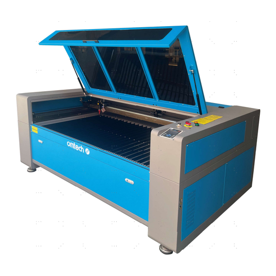
Page 8: Components
1.5 Components C C E E Front View A. Cover—The cover provides access to the main bay for placing and retrieving materials, as well as fixing the laser path alignment and other maintenance. Power to the laser is automatically cut when the cover is opened. B. - Page 9 G. Top Right Access Door—This door provides access to the Y-axis drag chain, X-axis motor, and controller. H. Bottom Front Access Door—This door provides access to the waste hopper for easy cleanup after each project. I. Inputs—This panel includes the ports for the machine's USB, computer, and internet connections. J.
- Page 10 Rear View A. Top Rear Access Door—This door opens to the laser bay, holding the laser tube and its connections. B. Main Power Switch—This switch controls the main power supply to the machine. C1: Main Power Socket—The socket connects to your main power supply. C2: Power Outlet—This outlet powers the water pump.
- Page 11 Laser Path A. Laser Tube—This long glass tube is filled with helium, D. 3rd Mirror—This adjustable-angle mirror moves nitrogen, and CO₂ gas and water cooled to safely produce with the laser head to allow the laser beam to travel your engraving laser. Its connection to the laser power supply along the X axis.
- Page 12 Connection Inputs A. USB Port—This port allows you to load and save designs and parameters directly onto the engraver. B. USB Line Port—This port connects to your control computer and its engraving software using any of its USB ports. C. Ethernet Port—This port connects to your control computer and its software either directly or via the internet.
- Page 13 Control Console Returns the machine to the saved default Stops work or returns to a previous parameters (See §4.4.14) menu Enters a command or confirms your Stops the current job selection Sets the starting point for the laser head Opens the Main menu (See §4.4.2) (See §4.4.13) Traces the outline of the current design Opens the Function menu (See §4.4.8)
- Page 14 Console Screen A. Graphic Display Area: Traces the processed file image during file preview display and processing. B. Parameter Display Area: Displays the file number, speed, and maximum power of the current processing file. C. Coordinate Display Area: Displays the coordinate value of the current position of the laser head. D.
-
Page 15: Safety Information
2. Safety Information 2.1 Disclaimer Your engraver may differ somewhat from those shown in this manual due to options, updates, etc. Please contact us if your engraving machine came with an outdated manual or if you have any other questions. 2.2 General Safety Instructions •... -
Page 16: Laser Safety
2.3 Laser Safety Instructions When used as instructed, this machine comprises a Class 1 laser system safe for users and bystanders. However, the invisible engraving laser, the laser tube, and its electrical connections remain EXTREMELY dangerous. Used or modified without care, they can cause serious property damage and personal injury including but not limited to the following: •... -
Page 17: Electrical Safety
2.4 Electrical Safety Instructions • ONLY use this device with a compatible and stable power supply with less than 5% fluctuation in its voltage. • DO NOT connect other devices to the same fuse, as the laser system will require its full amperage. Do not use with standard extension cords or power strips. - Page 18 This machine can be safely used with the following materials: Plastics • Acrylonitrile Butadiene Styrene (ABS) • Nylon (Polyamide, PA, etc.) • Polyethylene (PE) • High-Density Polyethylene (HDPE, PEHD, etc.) • Biaxially-Oriented Polyethylene Terephthalate (BoPET, Mylar, Polyester, etc.) • Polyethylene Terephthalate Glycol (PETG, PET-G, etc.) •...
-
Page 19: Installation
3. Installation 3.1 Installation Overview A complete working system consists of the laser engraving cabinet, its vents, an industrial water chiller, all applicable connection cables, and the laser and access keys. The cabinet can use designs provided by the enclosed engraving software by direct or internet connection with your computer;... -
Page 20: Electrical Grounding
Step 3. Check that you have received all of the following: a power cord, a ground wire, USB and Ethernet cables, a USB flash drive with engraving software included, an exhaust pipe with a hose clamp, a set of Allen keys, a tube of silicone sealant, an acrylic focusing tool, keys, and this manual. -
Page 21: Water Cooling System
3.5 Water Cooling Installation Using a water chiller (not incl.) is essential to your engraver’s performance and longevity. When this laser works without a properly maintained cooling system, its glass tube WILL explode from excess heat. To install your chiller, follow the instructions in its separate manual. Always fill it with distilled water. Using deionised or tap water will gradually degrade the quality of your engraver and may even cause dangerous mineral buildup in the cooling system. -
Page 22: Exhaust System
3.6 Exhaust System This engraver doesn’t come with an inbuilt exhaust fan. Follow the steps to set an exhaust system before use. 1. Connect the provided exhaust pipe to the port of the laser engraver, and the other end to your exhaust fan. Expand the pipe if longer is needed. -
Page 23: Initial Testing
3.9 Initial Testing Emergency Shutoff Because of the risk of fire and other hazards during engraving, this engraver includes a large and easy-to-reach emergency stop button near the control panel. Press it down to stop the laser tube instantly. When your engraver arrives, its e-stop is already pressed. Release the e-stop and press the reset button to allow the laser to function. -
Page 24: Security
Water Shutoff Because of the danger posed by an uncooled laser tube, this engraver also shuts off the laser automatically when the water cooling system malfunctions. After ensuring that the emergency stop button and cover protection both work, you should also test that the water shutoff works properly before conducting any other work on your machine. -
Page 25: Operation
4. Operation 4.1 Operation Overview Operate this laser marking machine only in accordance with all the instructions provided in this manual. Failure to follow the proper guidelines detailed here can result in property damage and personal injury. This section will address only some of the options and features provided by the operation software. Before beginning to use the machine, make sure that you have read this entire manual (particularly the Safety Information above), the separate software manual, and any and all warnings provided on the machine itself. -
Page 26: Instructions For Specific Materials
The threshold for the lowest setting is 10%. The laser will not fire at any setting lower than this. It is NOT recommended to use the laser tube at full capacity, especially for extended periods. The recommended maximum power setting is 70%, as prolonged use above that amount will shorten your laser's service life. To increase engraving depth, increase the amount of energy per unit area by increasing the laser's power or the number of loops or by slowing down the speed parameter. - Page 27 Glass When engraving glass, generally use high power and low speed. As with ceramics, it can be helpful to run more loops at lower settings to avoid cracks. Care must be taken when engraving fiberglass and carbon fibre to avoid combinations of settings that produce a laser intensity great enough to damage the structural integrity of its component fibres, producing blurry marking.
- Page 28 Rubber The various compositions and densities of rubber cause slightly varying engraving depth. Testing various settings on sample pieces of your specific rubber is highly recommended for best results. When engraving rubber, generally use a consistent high power setting and create your effects by varying the laser's speed. Microporous rubber materials require a significantly higher speed than standard rubber.
-
Page 29: Control Console
4.4 Control Console Instructions 4.4.1 Overview You can control your engraver directly from the built-in control panel, through a direct connection with your computer, or over the internet. For details on operating your engraving software, see its separate manual. The built-in control panel can operate the laser manually or engrave designs loaded onto flash drives and external hard drives connected to the USB port on the right side of the cabinet. -
Page 30: Menu Button
4.4.2 Menu Button Press Menu on the main interface to enter the Menu interface: Push ▲ or ▼ to select items, and then press Enter to enter the corresponding submenu. 4.4.3 Setting the Laser Speed Select Speed on the Menu interface, and the following dialogue box will appear: A cursor will appear when pushing ◄... -
Page 31: File Management
4.4.5 File Management Select File on the Menu interface, and the following dialogue box will appear: The system will automatically read the memory files. The file name and the work times will be listed and the selected file will be previewed in the upper right corner. Different memory files can be selected by using ▲ or ▼. Press Enter to preview the selected file on the main interface. -
Page 32: Reading Usb Files
4.4.6 Reading USB Files If Udisk+ is pressed, the display will show: • Read Udisk: Reads the file list in the inserted USB drive. • Copy to Memory: Copies the target file to the system. • Delete: Deletes the selected file from the USB drive. The system supports FAT16 and FAT32 formats, but files can only be identified when placed in the root directory of the flash drive. -
Page 33: Engraving Layer Adjustment
4.4.8 Adjusting Engraving Layers When the system is idle or the work is finished, press Enter to enter the layer parameter section. Push ▲ or ▼ to select the intended layer. Press Enter to check the selected layer's parameters as shown below: Layer0 Layer0 Speed... -
Page 34: Z Axis
4.4.11 Adjusting the U Axis When U Move is selected, push ◄ or ► to control the movement of the U axis. This can be used to control the rotational position of a rotary axis or the linear position of an automatic feed (both sold separately) if either is installed. -
Page 35: Setting The Origin
4.4.15 Setting the Origin When Origin Set+ is selected, press Enter and the display will show: Press Fn to select an item. When Multi Origin Enable is selected, press Enter to enable or disable the item. When enabled, the small box will be red and, when disabled, the small box will be grey. When selecting Set Origin or Next Origin, push ◄... -
Page 36: Default Parameter Adjustment
4.4.16 Adjusting Default Parameters When Set Fact. Para. is selected, the following interface will be displayed: Push ◄ or ► and ▲ or ▼ to select a password and press Enter to save it. The current parameters of the machine will be stored as its defaults. -
Page 37: Ip Address
4.4.20 Setting the Machine's IP Address When IP Setup+ is selected, press Enter and the display will show: Press Fn to select an item, and push ◄ or ► and ▲ or ▼ to change the parameters. The default address of the engraver is 192.168.1.100. -
Page 38: Screen Interface
4.4.22 Setting the Screen Reference When Screen Origin is selected, press Enter and the display will show: This interface sets the relative position of the origin. Different origin positions can generate different reflections of the graph over the X/Y axis. The operation method is the same as those described above. 4.4.23 Alarm Display During the operation of the system or the running of the machine, some alarm information may pop up if there is a water protection error etc. -
Page 39: Maintenance
• The whole laser machine including the other components such as the water cooling system must be checked every month and cleaned where required. For video instructions on general maintenance, see our YouTube channel’s guide “OMTech Training—Cleaning Your Laser Engraver.”... -
Page 40: Main Bay & Engraver
If the water remains visibly clean at all times, it is still recommended that you clean the water tank about once a month as a precaution, changing the water as you do so. Also follow any further maintenance requirements as described in the chiller’s separate manual. - Page 41 Once positioned over your clean lens-cleaning tissue, remove the lens from the lens holder by carefully turning the lens holder and letting the lens and its O-ring drop onto the cleaning cloth. Examine the O-ring and, if necessary, clean it with a cotton bud and a lens-cleaning tissue or cloth. Remove coarse dust as well as possible by blowing air onto the lens surface.
-
Page 42: Mirrors
5.3.4 Cleaning the Mirrors The mirrors should be similarly cleaned if there is any debris or haze on their surface to improve performance and avoid permanent damage. The 1st mirror is located in the back left of the machine beyond the far end of the Y axis. The end of the laser tube closest to this mirror is itself a semitransparent mirror that should be checked at the same time. -
Page 43: Laser Tube
5.4.1 Laser Tube Alignment To test the alignment of the laser tube with the 1st mirror, cut out a piece of tape and place it on the mirror's frame. DO NOT place the tape directly onto the mirror. Turn on the machine and set the power level to 15% or lower. Press PULSE to manually fire the laser. -
Page 44: First Mirror
5.4.2 1st Mirror Alignment After ensuring the laser is well aligned between the laser tube and 1st mirror, check the alignment between the 1st and 2nd mirrors. First, use the direction arrows on the control panel to send the 2nd mirror to the back of the bed along the Y axis. -
Page 45: Second Mirror
5.4.3 2nd Mirror Alignment After ensuring the laser is well aligned between the 1st and 2nd mirrors, check the alignment between the 2nd and 3rd mirrors. Repeat the steps and adjustments above, taking care to use the tape on the mirror's frame and not its surface. 5.4.4 3rd Mirror Alignment After ensuring the laser is well aligned between the 2nd and 3rd mirrors, check the alignment between the 3rd mirror and the workbed. -
Page 46: Parts Replacement
QR code to the right. Come join the OMTech community at our official laser group on Facebook or visit the company forums at omtechlaser.com! Check our YouTube channel for helpful hints and instructional videos.
Need help?
Do you have a question about the USB1610d and is the answer not in the manual?
Questions and answers