Table of Contents
Advertisement
Available languages
Available languages
Quick Links
Air Flux
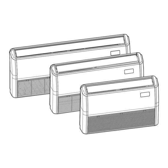
AF2-CF 36-1 | AF2-CF 45-1 | AF2-CF 56-1 | AF2-CF 71-1 | AF2-CF 80-1 | AF2-CF 90-1 | AF2-CF
112-1 | AF2-CF 140-1
de
VRF-Inneneinheit als Decken- oder Bodengerät
en
Ceiling floor type VRF Indoor Unit
es
Unidad interior VRF tipo suelo techo
fr
Unité intérieure VRF de type console, plafonnier
it
Unità interna VRF a soffitto
pl
Przypodłogowo-podstropowa jednostka wewnętrzna
VRF
Installations- und Bedienungsanleitung – Originalanleitung . . . . . . . . . . . . . . . . . . . . . 2
Installation and user manual - Original instructions . . . . . . . . . . . . . . . . . . . . . . . . . . . 34
Manual de instalación y de usuario - instrucciones originales . . . . . . . . . . . . . . . . . . . 65
Notice d'installation et d'utilisation . . . . . . . . . . . . . . . . . . . . . . . . . . . . . . . . . . . . . . . . 98
Manuale di installazione ed uso - Istruzioni originali . . . . . . . . . . . . . . . . . . . . . . . . . . 131
Instrukcja montażu i obsługi. . . . . . . . . . . . . . . . . . . . . . . . . . . . . . . . . . . . . . . . . . . . . 164
Advertisement
Table of Contents

Related Manuals for Bosch Air Flux AF2-CF 36-1


Summary of Contents for Bosch Air Flux AF2-CF 36-1
- Page 1 Air Flux AF2-CF 36-1 | AF2-CF 45-1 | AF2-CF 56-1 | AF2-CF 71-1 | AF2-CF 80-1 | AF2-CF 90-1 | AF2-CF 112-1 | AF2-CF 140-1 VRF-Inneneinheit als Decken- oder Bodengerät Installations- und Bedienungsanleitung – Originalanleitung ..... 2 Ceiling floor type VRF Indoor Unit Installation and user manual - Original instructions .
- Page 2 Inhaltsverzeichnis Keine Störung des Klimageräts ....22 Inhaltsverzeichnis Störungen, die nicht angezeigt werden ... . 24 Störungs-Codes .
- Page 3 Symbolerklärung und Sicherheitshinweise ▶ Für die Installation die beiliegenden Zubehörteile und angegebenen Symbolerklärung und Sicherheitshinweise Komponenten verwenden. Ansonsten kann das Gerät herunterfallen. Außerdem sind Funktionsstörungen und Lecks möglich. Es besteht Symbolerklärung Stromschlag- und Brandgefahr. ▶ Einen festen, tragfähigen Installationsort auswählen, der das Geräte- Warnhinweise gewicht tragen kann.
- Page 4 Symbolerklärung und Sicherheitshinweise ▶ Vor der Installation den Verlauf vorhandener Kabel-, Wasser- und 1.2.1 Wichtige Hinweise für den Betreiber Gasleitungen in Wänden, Böden und Decken überprüfen. Vor dem • Bei Unsicherheiten bezüglich des Betriebs des Geräts wenden Sie Bohren die Sicherheit der Arbeiten mit dem Betreiber abstimmen sich an das Installationspersonal.
- Page 5 Mit der CE-Kennzeichnung wird die Konformität des Produkts mit allen anzuwendenden EU-Rechtsvorschriften erklärt, die das Anbringen dieser Kennzeichnung vorsehen. Der vollständige Text der Konformitätserklärung ist im Internet verfüg- bar: www.bosch-homecomfort.de. Zubehör Überprüfen, ob das folgende Zubehör vollständig im Lieferumfang enthalten ist: Bezeichnung...
-
Page 6: Vor Der Installation
Vor der Installation Separat zu beschaffendes Zubehör: Entfernen Sie das Verpackungsmaterial aus der Spirale (einige Mo- delle) Modell AF2-CF 36-1 – AF2-CF 80-1 – AF2- 1. Die Pappe nach innen drücken, damit sie nicht eingeklemmt wird. AF2-CF 71-1 CF 140-1 2. -
Page 7: Installation
Installation Platzbedarf bei der Montage Das Gerät kann senkrecht montiert werden, wenn im Vorfeld Vorkehrungen für die richtige Ausrichtung getroffen wurden. 0010053492-001 Bild 4 Luftstromlamelle Luftaustritt Lufteintritt Die Aufstellfüße sind optional und können separat erworben werden. Bei Installationen, bei denen in Aufenthaltsräumen mechanische Verbin- dungen sichtbar sind, sicherstellen, dass im selben Raum und an dersel- ben Wand wie das Gerät in maximal 2 Metern Entfernung ein Fühler montiert ist. - Page 8 Installation Abmessungen 6.1.1 Abmessungen des Gerätegehäuses 0010053494-001 Bild 5 Außenmaße und Größe der Luftaustrittsöffnung (Einheit: mm) Produkttyp AF2-CF 36-1 – AF2-CF 56-1 1069 221 siehe un- Ø 25 siehe unten AF2-CF 71-1 – AF2-CF 90-1 1284 1199 Ø 25 AF2-CF 112-1 – AF2-CF 140-1 1649 1565 Ø...
-
Page 9: Installation Der Inneneinheit
Installation Installation der Inneneinheit HINWEIS 6.2.1 Verlegungsrichtung der Rohre ▶ Die runden Öffnungen herausschneiden, um zu vermeiden, dass ▶ Kältemittel- und Ablaufrohr können an zwei Stellen herausgeführt beim Anschließen der Rohre Fremdkörper in das Gerät gelangen werden: unten rechts oder hinten rechts. (Abb. - Page 10 Installation ▶ Für die Montage oder Demontage der Rohre zwei Schraubenschlüs- sel verwenden, einen herkömmlichen und einen Drehmomentschlüs- sel. 0010020835-002 Bild 9 Kältemittelöl auftragen 0010020833-002 Bild 8 WARNUNG Herkömmlicher Schraubenschlüssel Giftige Gase Drehmomentschlüssel ▶ Vorsicht beim Schweißen von Kältemittelrohren. Überwurfmutter Rohrverschraubung ▶...
- Page 11 Installation Fixieren der Kältemittelrohre Zum Befestigen Stahl-Verbindungswinkel oder Aufhängungen aus Rund- stahl verwenden. Bei gemeinsamer Aufhängung von Flüssigkeits- und Gasleitung ist die Größe der Flüssigkeitsleitung ausschlaggebend. Rohr-Außen- ≤ 20 20 – 40 ≥ 40 durchmesser (mm) Abstand hori- zontaler Leitun- gen (m) 0010020837-002 Abstand vertika-...
- Page 12 Installation 0010053266-001 Bild 12 Kondensatwannenausgang Ablaufschlauch PVC-Ablauf- und Dämmrohr Kabelbinder <50mm 90° Schräg Geneigt Grat Zerkratzt Installation des Ablaufrohrs ▶ Als Ablaufrohr PVC-Rohr verwenden (Außendurchmesser: 30– 32 mm, Innendurchmesser: 25 mm). Entsprechend den Gegeben- heiten vor Ort können die Rohre in den benötigten Längen beim Händler, beim örtlichen Kundendienst oder direkt im Handel erwor- ben werden.
- Page 13 Installation Installationsanforderungen für Ablaufleitungen 6.4.2 Rohre bündeln ▶ Ablaufleitungen mit Abwärtsneigung verlegen. Das Gefälle der Ab- 1. Rohrbündel wie folgt herstellen: Netzkabel oben, Anschlussrohr in laufleitung muss so gewählt werden (mit einer Neigung von mehr als der Mitte, Ablaufrohr unten. 1/100), dass das Kondensat leicht abfließen kann.
- Page 14 Installation Anschlussart von Ablaufrohren mit Ablaufpumpe 1000~1500 ≥1/100 0010053470-001 Bild 18 ▶ Das Abzweigrohr der Ablaufleitung sollte entlang der Strömungsrich- tung des Wassers geneigt sein, und das Gefälle sollte nicht weniger als 1 % betragen. Bei waagerechten Rohren alle 1–1,5 m, bei senk- rechten Rohren alle 1,5–2,0 m Aufhängungen anbringen.
- Page 15 Installation ▶ Zwischen Netz- und Kommunikationsleitungen muss ein Mindestab- stand von 300 mm eingehalten werden, um elektrische Interferen- zen, Störungen und Schäden an elektrischen Bauteilen zu vermeiden. Diese Leitungen dürfen nicht mit Rohren und Ventilen in Berührung kommen. ▶ Kabel entsprechend den jeweiligen Anforderungen auswählen. ▶...
- Page 16 Installation ▶ Kältemittelrohre sowie Netz- und Kommunikationsleitungen nicht an- Modell Stromversorgung einander befestigen. Wenn Netz- und Kommunikationsleitung paral- Volt MCA MFA kW lel verlaufen, einen Mindestabstand von 300 mm einhalten, um AF2-CF 36-1 220- 0,20 0,05 0,16 Interferenzen zwischen den Signalquellen zu vermeiden. AF2-CF 45-1 0,28 0,05 0,22...
- Page 17 Installation ▶ Kommunikationsleitung auf der Hauptleiterplatte an die Anschluss- ▶ Die Super Link-Kommunikationsleitung der Außen- und Inneneinhei- klemme "CN10" an die Markierungen "M1" und "M2" anschließen. Bei ten mit der Regelventil-Abschaltfunktion ist insgesamt bis zu 600 m der Super Link-Kommunikation muss die Polung nicht beachtet wer- lang, sodass verschiedene Anschlusstopologien möglich sind.
- Page 18 Installation ▶ Die Super Link-Kommunikationsleitung für Außen- und Inneneinheiten ohne Regelventil-Abschaltfunktion ist insgesamt bis zu 2000 m lang, sodass verschiedene Anschlusstopologien möglich sind. Das folgende Bild zeigt die Reihenschaltung. × × IDU 1# IDU (n-1)# IDU n# CN23 CN10 CN10 CN10 ···...
- Page 19 Installation X1/X2-Anschluss für Kommunikationskabel X1- und X2-Kommunikationskabel dienen in erster Linie für den An- schluss an die Kabel-Fernbedienung. Unterstützt werden die Konfigura- X1 X2 D1 D2 D1 D2 D1 D2 tionen "ein Regler für eine Inneneinheit" und "zwei Regler für eine Inneneinheit".
- Page 20 Installation Anschluss einer externen Leiterplatte (begrenzt auf Außeneinheit VORSICHT und Anlagenkonfiguration) Die externe Leiterplatte ist ein Anschlussmodul außerhalb der Hauptlei- An der Funktionsmodul-Adapterplatte dürfen nur Datenleitungen ange- terplatte mit Display, Funktionsmodul-Adapterplatte und optional mit schlossen werden. freien Funktionsmodulen 1 und 2. Das Display ist über eine vieradrige Kommunikationsleitung mit der Alarmsignal Hauptleiterplatte verbunden und dort an CN30 angeklemmt.
- Page 21 Probelauf 6.5.4 Verbindungsstellen zwischen elektrischen Komponenten Anlagenkonfiguration ▶ Nach dem Fertigstellen von Verdrahtung und Anschlüssen die Leitun- gen mit Kabelbindern befestigen, sodass sich Anschlüsse nicht Störungs-Codes und Definitionen durch äußere Krafteinwirkung lösen. Anschlussleitungen müssen ge- rade verlaufen, sodass die Abdeckung des Klemmenkastens gerade Stö- Inhalt aufsitzt und dicht abschließt.
-
Page 22: Störungsbehebung
Anlagenkonfiguration Stö- Inhalt Stö- Inhalt rungs- rungs- Code Code Störung PM2.5-Fühler Einstellungsfehler Drehzahlregelung Störung CO2-Fühler Motor Phasenverlustschutz Störung Formaldehyd-Fühler Tab. 9 Störungs-Codes Störung Smart-Eye-Fühler Störungs- Inhalt T0 (Temperaturfühler Frischluftansaugung) Kurzschluss oder Code Unterbrechung Ölrücklauf oder Vorwärmung läuft Obere Buchse Trockenkugel-Temperaturfühler Kurzschluss Selbstreinigung läuft oder Unterbrechung Betriebsartenkonflikt (verwendetes Kommunikationspro-... - Page 23 Störungsbehebung Normales Phänomen und keine Störung des Klimageräts Falls bei der Verwendung des Klimageräts die folgenden Phänomene auftreten, sind diese als normal zu betrachten. Sie können entweder durch Befol- gung der nachstehenden Schritte beseitigt werden, oder es sind keine Maßnahmen erforderlich. Symptom Mögliche Ursachen Schritte zur Störungsbehebung...
- Page 24 Störungsbehebung Störungen, die nicht angezeigt werden Symptom Mögliche Ursachen Schritte zur Störungsbehebung Einheit startet nicht Stromausfall (die Stromversorgung des Gebäudes ist unter- Warten, bis die Stromversorgung wiederhergestellt ist. brochen). Die Einheit wurde ausgeschaltet. Einheit einschalten. Die Inneneinheit ist Bestandteil einer Kli- maanlage mit mehreren angeschlossenen Inneneinheiten.
- Page 25 Störungsbehebung Störungs-Codes In den folgenden Fällen das Klimagerät sofort ausschalten, die Stromversorgung unterbrechen und Kontakt zum örtlichen Kundendienstzentrum für Kli- mageräte aufnehmen. Der Störungs-Code wird auf dem Anzeigefeld und auf dem Display des kabelgebundenen Reglers angezeigt. Diese Störungen dür- fen nur von qualifizierten Fachkräften bearbeitet werden. Sie werden hier nur zur Information beschrieben. Code Definition Not-Aus...
- Page 26 Störungsbehebung Code Definition Tph-Temperaturfühler für vorgeheizte Frischluft Kurzschluss oder Unterbrechung TA-Luftauslass-Temperaturfühler Kurzschluss oder Unterbrechung Ausfall Luftauslass-Feuchtefühler Ausfall Rückluft-Feuchtefühler Ausfall Feuchtkugel-Temperaturfühler (oben) Ausfall Feuchtkugel-Temperaturfühler (unten) Ausfall Kältemittel-Leckfühler T2A-Temperaturfühler an Wärmetauscher-Eintritt Kurzschluss oder Unterbrechung T2-Temperaturfühler in Wärmetauscher-Mitte Kurzschluss oder Unterbrechung T2-Temperaturfühler in Wärmetauscher-Mitte Übertemperaturschutz T2B-Temperaturfühler in Wärmetauscher Kurzschluss oder Unterbrechung Störung EEPROM Hauptleiterplatte Störung EEPROM Displayeinheit der Inneneinheit...
-
Page 27: Wartung
Informationen Bedienungsanleitung Informationen Bedienungsanleitung 10.1 Systemübersicht 0010053493-001 Bild 36 Anschlusskabel HINWEIS Regler (optional) Inneneinheit In dem in der Tabelle oben angegebenen Temperaturbereich läuft die Obere und untere Luftstromlamelle Einheit stabil. Wenn die Raumtemperatur außerhalb des normalen Be- Displayeinheit triebsbereichs der Einheit liegt, schaltet die Einheit gegebenenfalls ab. Stromversorgung und Erdungskabel Ein Störungs-Code wird angezeigt. -
Page 28: Luftfilter Reinigen
Informationen Bedienungsanleitung 5. Luftfilter reinigen HINWEIS Während des Betriebs der Einheit sammelt sich Staub auf dem Filter an. Für einen einwandfreien Betrieb muss dieser Staub entfernt wer- Sicherheitshinweise für die Wartung. den. ▶ Inneneinheit und Fernbedienung mit einem trockenen Tuch reinigen. –... - Page 29 Informationen Bedienungsanleitung Wartung vor dem Abschalten für einen längeren Zeitraum (z. B. am Wartung von Gebläsegehäuse, Motor und Lüfterwalzen Ende einer Saison) 1. Befestigung des Lufteintrittsgitters nach unten ziehen. ▶ Inneneinheit etwa einen halben Tag lang im Ventilatorbetrieb laufen 2. Schrauben entfernen. lassen, um die Komponenten in der Einheit zu trocknen.
- Page 30 Informationen Bedienungsanleitung 0010053481-001 Bild 47 3. Rohrhalterungsabdeckung demontieren. 0010052249-001 Bild 45 0010053482-001 Bild 48 Riegel Seitenwandkante Rohrhalterungsabdeckung (Vorderansicht) Begrenzungsnut Rohrhalterungsabdeckung (Seitenansicht) Schlitz 4. Verdampfer herausnehmen. Positionierungsstange 5. Wartungstätigkeiten am Verdampfer ausführen. Begrenzungsnut Begrenzungsriegel Arretierung Instandhaltung von Kondensat-Auffangbehälter und Verdampfer 1. Geräteverkleidungen demontieren. 0010053483-001 Bild 49 0010053480-001...
- Page 31 Informationen Bedienungsanleitung 10.4 Symptome, die keine Störung sind • Im Kühl- und im Entfeuchtungsbetrieb der Einheit kann ein leises, an- haltendes Rasseln zu hören sein, das durch den Betrieb der Ablauf- Die folgenden Symptome können während des Normalbetriebs der Ein- pumpe verursacht wird.
-
Page 32: Umweltschutz Und Entsorgung
B. „Europäische Richtlinie 2012/19/EG über Elektro- und Elekt- unseren Datenschutzbeauftragten wenden: Datenschutzbeauftragter, ronik-Altgeräte“. Diese Vorschriften legen die Rahmenbedingungen fest, Information Security and Privacy (C/ISP), Robert Bosch GmbH, Post- die für die Rückgabe und das Recycling von Elektronik-Altgeräten in den fach 30 02 20, 70442 Stuttgart, DEUTSCHLAND. - Page 33 Anhang Anhang 13.1 Anschlussplan CN10 CN22 CN18 CN55 M1 M2 X1 X2 B1 B2 B3 D1 D2 0010052850-002 Bild 50 Anschlussplan Anschlussklemme für Kommunikationsleitung Anschlussklemme für Funktionsmodul-Adapterplatte Anschlussklemme für EIN/AUS-Fernsignal Reserviert Anschlussklemme für Alarmsignal Netzkabelanschluss und Erdungsklemme Wasserstandsschalter Kondensatpumpe Displayeinheit [10] Elektronisches Expansionsventil T2A Temperaturfühler Wärmetauscher-Eingang T2B Temperaturfühler Wärmetauscher-Ausgang...
- Page 34 Table of contents Error codes........56 Table of contents 10 Informations Owners Manual.
- Page 35 Explanation of symbols and safety instructions ▶ Mount the air conditioner in a place that is sturdy enough to bear its Explanation of symbols and safety instructions weight. If the base is not secured properly, the air conditioner may drop leading to damages and injuries. Explanation of symbols ▶...
- Page 36 Explanation of symbols and safety instructions HCaution Warnings ▶ Wear protective gloves during installation and maintenance work. ▶ This unit consists of electrical components and hot parts (danger of electric shock and burns). ▶ Install the water discharge piping according to the steps described in this manual, and make sure that the water discharge is smooth, and ▶...
-
Page 37: Before Installation
Product Information Product Information Electrical compliance This equipment conforms to EN/IEC 61000-3-12 specifications. Accessories Verify that the air conditioner includes the following accessories: Name Quantity Appearance Purpose Installation and user manual This manual Insulation pipe Thermal insulation and anti-condensation effect of piping connections Flare nut For use in the installation works of connecting piping Cable tie... -
Page 38: Choosing An Installation Site
Choosing an installation site Choosing an installation site ▶ The indoor unit shall not be installed close to the ceiling, and it shall ▶ Choose a site that fully complies with the following conditions and be kept level or within 1° inclination towards the drainage side. (For user requirements to install the air conditioning unit: the models without drainage pumps, an inclination of 1/100 towards –... - Page 39 Installation Dimensions 6.1.1 Dimensions of the unit body 0010053494-001 Fig. 5 External dimensions and size of air outlet opening (unit: mm) Product Type AF2-CF 36-1 – AF2-CF 56-1 1069 Ø 25 see below below AF2-CF 71-1 – AF2-CF 90-1 1284 1199 Ø...
-
Page 40: Indoor Unit Installation
Installation Indoor unit installation NOTICE 6.2.1 Routing direction of pipes ▶ Cut the circular holes to prevent unwanted objects from inside the ▶ The refrigerant pipe and the drain pipe can be routed in two appliance when connecting the pipes (Fig, 6). directions, bottom right and rear right. - Page 41 Installation WARNING Toxic gases ▶ Take precautions when welding the refrigerant pipes. ▶ Before you weld the refrigerant pipes, fill the pipes with nitrogen to discharge the air in the pipes. If no nitrogen is filled in during welding, an oxide layer will form inside the piping which may cause the air conditioning system to malfunction.
- Page 42 Installation 6.3.7 Heat insulation treatment of gas-liquid piping connections Water discharge piping installation of the indoor unit 6.4.1 Drainage pipe installation for the indoor unit The heat insulation treatment is carried out on the piping at the gas and liquid sides of the indoor unit respectively. Drainage pipe insulation ▶...
- Page 43 Installation <50mm 0010053484-001 Fig. 14 Downslope piping PVC adhesives Drain pipe PVC pipe (Ø 15mm) or rigid PVC pipe (VP-16) 0010053485-001 Fig. 13 NOTICE 0010022752-001 Fig. 15 ▶ Make sure all the connections in the piping system are properly sealed to prevent water leakages. Protection piping Wall Water drainage pipe...
- Page 44 Installation 3. Apply some pressure to ensure the pipes are tightly affixed to the wall. 4. Open the wall hole sleeve cover. 5. Insert the sleeve cover around the pipes and secure it in place. 6.4.3 Connection mode of drainage pipes Connection mode of drainage pipes using natural drain outlet ▶...
-
Page 45: Power Cord Connection
Installation 6.4.4 Installation of sealing clay and wall hole sleeve cover 6.5.1 Power cord connection ▶ Tidy up the wrapped pipe body. ▶ Use a dedicated power supply for the indoor unit that is different from the power supply for the outdoor unit. ▶... - Page 46 Installation Refer to table 5 and 6 for the specifications of the power cord and communication wire. A wiring capacity that is too small will cause the electrical wiring to become too hot. This causes the device to be damaged or even catch fire. Model Power supply Volts MCA MFA kW...
- Page 47 Installation 6.5.3 Communication wiring Terminal Description CN1: L, N Power supply WARNING CN2: D1, D2 Group control communication ▶ Connect the shielding nets at both ends of the shielded wire to the CN6: X1, X2 Communication to controller grounding screw. ▶...
- Page 48 Installation CN23 IDU 1# IDU 10# × × × × DOWN CN10 CN10 ··· AF2-PBR IDU 2-9# IDU 20# IDU 11# DOWN × × × × CN10 CN10 ··· AF2-PBR IDU 12-19# IDU 30# IDU 21# IDU 29# × × ×...
- Page 49 Installation × × IDU 1# IDU (n-1)# IDU n# CN23 CN10 CN10 CN10 ··· 2-(n-2)# IDU 0010052882-001 Fig. 26 Indoor and outdoor units communication wire (M1/M2) with uniform power supply Outdoor unit CAUTION Communication wire In the case of the Super Link communication without the function of Power cable power-down control valve, the indoor unit shall be uniformly powered.
- Page 50 Installation X1/X2 communication cable connection X1 and X2 communication cables are mainly used to connect to the wired controller. The configuration “one controller to one indoor unit” X1 X2 D1 D2 D1 D2 D1 D2 and “one two controllers to one indoor unit” are supported. The total length of X1 and X2 communication cables can be up to 200 m.
- Page 51 Installation External board connection (limited to outdoor unit and system CAUTION configuration) The external board is a connection module outside the main board, Only weak current connection should be used for the function module including a display panel, a function module adapter board and optional adapter board.
- Page 52 Test run 6.5.4 Handling the electrical wiring connection points On-site configuration ▶ Once the wiring and connections are done, use cable ties to secure the wiring properly so that the connection joint cannot be pulled Error codes and definitions apart by external force. The connection wiring must be straight, so that the cover of the electrical box is level and can be closed tightly.
-
Page 53: Troubleshooting
Troubleshooting Error Content Error Content code code Formaldehyde sensor fault Oil return or preheating operation Smart eye sensor fault Self-cleaning operation T0 (fresh air intake temperature sensor) short-circuited or Mode conflict (using V8 communication protocol) open-circuited Defrosting operation Upper shed dry bulb sensor short-circuited or open-circuited Static pressure test Lower shed dry bulb sensor short-circuited or open-circuited Remote shut-down... - Page 54 Troubleshooting Normal phenomenon rather than air conditioner fault In case of the following phenomena during the use of the air conditioner, they are normal and can be removed by following the steps below or no measures are required. Symptom Possible causes Troubleshooting steps A white mist is coming from the In humid regions, white mist may appear if there is a significant...
- Page 55 Troubleshooting Faults that are not displayed Symptom Possible causes Troubleshooting steps The unit does not start A power blackout has occurred (the power to the premises Wait for the power to come back on. has been cut-off). The unit is powered off. Power on the unit.
-
Page 56: Error Codes
Troubleshooting Error codes In case of the following circumstances, please stop the air conditioner immediately, cut off the power switch and contact the local air conditioner customer service center. The error code is displayed on the display panel and the wired controller display. These errors should only be investigated by a professional technician. - Page 57 Troubleshooting Code Definition Tph-fresh air temperature sensor after preheating short-circuited or disconnected TA-air outlet temperature sensor short-circuited or disconnected Air outlet humidity sensor failur Return air humidity sensor failure The wet bulb sensor (upper) failure The wet bulb sensor (lower) failure Refrigerant leak sensor failure T2A-heat exchanger inlet temperature sensor short circuit or disconnect T2-temperature sensor in the middle of heat exchanger short circuit or disconnect...
-
Page 58: System Overview
Informations Owners Manual Informations Owners Manual 10.1 System overview 0010053493-001 Fig. 36 Connection wires NOTICE Controller (optional) Indoor unit The unit performs stably in the temperature range given in above table. Upper and lower louvre If the indoor temperature is outside the unit's normal operating range, it Display panel may stop running and display an error code. - Page 59 Informations Owners Manual Method for cleaning the air filter ▶ The air filter can prevent the dust or other particles from entering the unit. If the filter is blocked, the unit will not work well. Clean the filter every two weeks when you use it regularly. ▶...
- Page 60 Informations Owners Manual Maintenance after a long period of non-use 7. Do maintenance on the motor and wind wheel. ▶ Check and remove anything that might be blocking the inlet and outlet vents of the indoor and outdoor units. ▶ Clean the unit casing and clean the filter. Re-install the filter before running the unit.
- Page 61 Informations Owners Manual 0010053481-001 Fig. 47 3. Remove the pipe clamping casing. 0010052249-001 Fig. 45 0010053482-001 Fig. 48 Latch bolt Side wall edge Pipe clamping casing (front view) Limiting groove Pipe clamping casing (side view) Slot 4. Remove the evaporator. Positioning rod 5.
-
Page 62: Symptoms That Are Not Faults
Informations Owners Manual 10.4 Symptoms that are not faults Symptom 7: The unit emits low noise • When the unit is in Auto, Cool, Dry and/or Heat modes, it may emit a The following symptoms may be experienced during the normal low continuous “hissing”... -
Page 63: Environmental Protection And Disposal
Environmental protection and disposal Environmental protection and disposal Environmental protection is a fundamental corporate strategy of the Bosch Group. The quality of our products, their economy and environmental safety are all of equal importance to us and all environmental protection legislation and regulations are strictly observed. - Page 64 Appendix Appendix 12.1 User wiring diagram CN10 CN22 CN18 CN55 M1 M2 X1 X2 B1 B2 B3 D1 D2 0010052850-002 Fig. 50 User wiring diagram Communication line terminal Function module adapter board terminal Remote ON/OFF signal terminal Reserved Alarm signal terminal Power cord and earth terminal Water level switch Drainage pump...
-
Page 65: Table Of Contents
Índice Códigos y definiciones de error....85 Índice Eliminación de fallos ....... . . 86 Explicación de los símbolos e indicaciones de Fallo independiente del equipo . -
Page 66: Explicación De Los Símbolos E Indicaciones De Seguridad
Explicación de los símbolos e indicaciones de seguridad ▶ Asegurarse de que se hayan instalado las piezas y los accesorios Explicación de los símbolos e indicaciones de requeridos. El uso de piezas no especificadas puede causar un error seguridad del equipo así como una fuga de agua, una descarga de corriente y fuego. -
Page 67: Información Importante Para El Usuario
Explicación de los símbolos e indicaciones de seguridad ▶ Controlar el esquema de conexiones eléctricas, de las tuberías de 1.2.1 Información importante para el usuario agua y de gas dentro de las paredes, del suelo y del techo antes de •... -
Page 68: Datos Sobre El Producto
UE que prevén la colocación de esta identificación. El texto completo de la declaración de conformidad está disponible en internet: www.bosch-homecomfort.es. Accesorios Verificar que el equipo incluya los siguientes accesorios: Nombre... -
Page 69: Antes De La Instalación
Antes de la instalación Accesorios adicionales que pueden ser adquiridos localmente: Extraer el material de embalaje del rodete del ventilador (algunos modelos) Modelo AF2-CF 36-1 – AF2-CF 80-1 – AF2- 1. Presionar la caja de cartón hacia dentro para evitar atascarla. AF2-CF 71-1 CF 140-1 2. -
Page 70: Instalación
Instalación Espacio necesario para la instalación La unidad permite una instalación vertical, siempre que previamente se lleve a cabo una posición correcta. 0010053492-001 Fig. 4 Lama Salida de aire Retorno de aire Los pies son opcionales y se pueden adquirir por separado. Para instalaciones con uniones mecánicas vistas en espacios ocupados, asegurese de que se haya situado una sonda dentro de 2 m horizontal- mente y en una pared de la misma estancia que la unidad. -
Page 71: Dimensiones
Instalación Dimensiones 6.1.1 Dimensiones del cuerpo de la unidad 0010053494-001 Fig. 5 Dimensiones externas y de la abertura de la salida de aire (unidad: mm) Tipo de producto AF2-CF 36-1 – AF2-CF 56-1 1069 véase Ø 25 véase abajo abajo AF2-CF 71-1 –... -
Page 72: Instalación De La Unidad Interior
Instalación Instalación de la unidad interior AVISO 6.2.1 Enrutado de la dirección de los tubos ▶ Cortar los taladros circulares para evitar objetos no deseados del ▶ El tubo de refrigerante y la tubería de desagüe se pueden enrutar interior del aparato cuando se conecten los tubos (fig, 6). hacia dos direcciones, inferior derecha y trasera derecha. - Page 73 Instalación ▶ Utilizar dos llaves inglesas al instalar o desmontar las tuberías o, alternativamente, una llave común y una llave dinamométrica. 0010020835-002 Fig. 9 0010020833-002 Aplicar aceite de refrigerante Fig. 8 ADVERTENCIA Llave normal Llave dinamométrica Gases tóxicos Tapa de toma de tubo ▶...
-
Page 74: Prueba De Estanqueidad
Instalación Fijación de las tuberías de refrigerante Para la fijación se deberían utilizar ángulos soporte de hierro o colgado- res de acero. Si la tubería para líquidos y el tubo de gas se suspenden juntos, el tamaño de la tubería para líquidos deberá prevalecer. Diámetro exte- ≤... - Page 75 Instalación 0010053266-001 Fig. 12 Salida de la bandeja para el agua Manguera de desagüe Tubo de vaciado y tubo de aislamiento de PVC Bridas <50mm 90° Rugoso Con pendiente Rebabas Rayaduras Instalación del tubo de descarga ▶ Utilizar tubos de PVC para las tuberías de desagüe (diámetro exte- rior: 30~32 mm, diámetro interior: 25 mm).
-
Page 76: Atar Los Tubos
Instalación Requisitos de la instalación de la tubería de desagüe de agua 4. Cubrir los materiales de aislamiento si los tubos son desplazados horizontalmente. ▶ Girar el tubo de desagüe de agua hacia abajo. La tubería hacia abajo se debe colocar (con una inclinación hacia abajo de más de 1/100) 5. -
Page 77: Instalación De La Masa De Sellado Y La Cubierta Del Manguito Del Agujero
Instalación Modo de conexión del tubo de drenaje utilizando bombas de drenaje 1000~1500 ≥1/100 0010053470-001 Fig. 18 ▶ La derivación del tubo de drenaje debería tener pendiente en la dirección de flujo del agua, y el gradiente no debería ser inferior al 1 %. -
Page 78: Conexión De Cable De Corriente
Instalación ▶ El cableado conectado debe ser equipado con un interruptor de des- Si no se puede utilizar el borne de conexión del cableado circular con el conexión que permita una separación de contacto de por lo menos revestimiento aislante: 3 mm. -
Page 79: Cableado De Comunicación
Instalación Corriente nominal Superficie de sección nominal (mm del aparato (A) Cables flexibles Cables para cableado fijo ≤ 3 0,5 - 0,75 1 - 2,5 0,75 - 1 1 - 2,5 6 - 10 1 - 1,5 1 - 2,5 10 - 16 1,5 - 2,5 1,5 - 4... - Page 80 Instalación • Las unidades interiores y exteriores se intercomunican mediante SuperLink (M1 M2). La conexión de este cable de comunicación debe provenir de la unidad exterior maestra. • El cableado de comunicación entre las unidades interiores y exterio- res debe conectar una unidad con la otra conexión desde la uni- dad exterior a la unidad interior final.
- Page 81 Instalación CN23 IDU 1# IDU 10# × × × × DOWN CN10 CN10 ··· AF2-PBR IDU 2-9# IDU 20# IDU 11# DOWN × × × × CN10 CN10 ··· AF2-PBR IDU 12-19# IDU 30# IDU 21# IDU 29# × × ×...
- Page 82 Instalación × × IDU 1# IDU (n-1)# IDU n# CN23 CN10 CN10 CN10 ··· 2-(n-2)# IDU 0010052882-001 Fig. 26 Cable de comunicación de unidades interiores y exteriores (M1/M2) con alimentación eléctrica uniforme Unidad exterior ATENCIÓN Cable de comunicación En el caso de la comunicación Super Link sin la función de la válvula de Cable de conexión control de apagado, la unidad interior será...
- Page 83 Instalación Conexión del cable de comunicación X1/X2 Los cables de comunicación X1 y X2 se utilizan, principalmente, para conectarlos al controlador por cable. La configuración "un controlador a X1 X2 D1 D2 D1 D2 D1 D2 una unidad interior" y "dos controladores a una unidad interior" sin com- patibles.
- Page 84 Instalación Conexión de la placa externa (limitada a la unidad exterior y a la con- ATENCIÓN figuración del sistema) La placa externa es un módulo de conexión fuera de la placa principal, Se debería utilizar solamente la conexión de corriente débil para la placa que incluye una panel de visualización, una placa adaptadora del módulo adaptadora del módulo de función.
-
Page 85: Manejo De Los Puntos De Conexión De Cableado Eléctrico
Prueba de funcionamiento 6.5.4 Manejo de los puntos de conexión de cableado eléctrico Configuración in situ ▶ Una vez que el cableado y las conexiones hayan sido realizadas, utili- zar las bridas para cables para asegurar el cableado correctamente, Códigos y definiciones de error de manera que la unión no pueda ser separada por fuerzas externas. -
Page 86: Eliminación De Fallos
Configuración in situ Códi- Contenido Códi- Contenido go de go de error error Fallo del panel de control del sensor Error ajuste modo de control velocidad Fallo sensor PM2.5 Protección pérdida fase motor Fallo sensor CO2 Tab. 9 Códigos de error Fallo sensor formaldehído Código Contenido... - Page 87 Eliminación de fallos Fenómeno normal en lugar de un fallo del equipo Si se producen los fenómenos siguientes durante el funcionamiento del equipo, son algo normal y se pueden eliminar siguiendo los pasos indicados abajo o bien no se requiere ninguna medida especial. Síntoma Posibles causas Pasos de eliminación de fallos...
-
Page 88: Errores Que No Se Visualizan
Eliminación de fallos Errores que no se visualizan Síntoma Posibles causas Pasos de eliminación de fallos La unidad no arranca Hubo un corte de luz (se interrumpió la corriente a las unida- Esperar a que retorne la corriente. des). La unidad está desconectada. Conectar la corriente de la unidad. -
Page 89: Códigos De Error
Eliminación de fallos Códigos de error Si se dan las siguientes circunstancias, detener el equipo inmediatamente, desconectar el interruptor principal y ponerse en contacto con el centro de asistencia al cliente del equipo de su zona. El código de error se muestra en la pantalla y en la pantalla del regulador de cable. Estos errores sólo deben ser investigados por un técnico profesional. - Page 90 Eliminación de fallos Código Definición Cortocircuito o desconexión sensor temperatura aire fresco Tph después del precalentamiento Cortocircuito o desconexión sensor temperatura salida aire TA Fallo sensor de humedad salida aire Fallo sensor humedad aire retorno Fallo sensor (superior) bulbo húmedo Fallo sensor (inferior) bulbo húmedo Error de sensor de fuga de refrigerante Cortocircuito eléctrico o desconexión sensor temperatura entrada intercambiador de placas T2A...
-
Page 91: Manual De Información Del Usuario
Manual de información del usuario Manual de información del usuario 10.1 Vista general del sistema 0010053493-001 Fig. 36 Cables de conexión AVISO Control (opcional) Unidad interior La unidad trabaja de manera fiable en el rango de temperatura presen- Lama superior e inferior tado en la tabla superior. - Page 92 Manual de información del usuario 5. Limpiar el filtro de aire AVISO El polvo se acumula en el filtro durante el funcionamiento de la uni- dad y necesita ser retirado del filtro; caso contrario, la unidad no tra- Notas en cuanto a la seguridad por el mantenimiento. bajará...
-
Page 93: 10.3.1 Mantenimiento De Piezas Y Componentes Convencionales
Manual de información del usuario Mantenimiento antes de un periodo de parada mayor (p. ej. al final Carcasa de ventilador y el mantenimiento del molinillo de una temporada) 1. Tirar hacia abajo del fijador de la rejilla de aire de entrada. ▶... -
Page 94: Síntomas Que No Son Fallos
Manual de información del usuario 0010053481-001 Fig. 47 3. Retirar el revestimiento de la abrazadera de tubo. 0010052249-001 Fig. 45 0010053482-001 Fig. 48 Perno de la pestaña de retención Esquina del muro lateral Revestimiento de la abrazadera de tubo (vista frontal) Ranura limitadora Revestimiento de la abrazadera de tubo (vista lateral) Ranura de conexión... - Page 95 Manual de información del usuario Síntoma 1: la unidad no funciona Síntoma 8: conmutación desde el modo refrigeración/calefacción al modo solo ventilación • En caso de pulsar el botón ON/OFF en el mando a distancia, la unidad no inicia inmediatamente. •...
-
Page 96: Protección Del Medio Ambiente Y Eliminación De
Adicionalmente, el reciclaje de desperdi- empresas afiliadas a Bosch. En algunos casos, pero solo si se asegura cios electrónicos, ayuda a cuidar los recursos naturales. -
Page 97: Anexo
Anexo Anexo 13.1 Esquema de conexiones eléctricas CN10 CN22 CN18 CN55 M1 M2 X1 X2 B1 B2 B3 D1 D2 0010052850-002 Fig. 50 Esquema de conexiones eléctricas Borne de conexión de la línea de comunicación Borne de conexión de la placa adaptadora del módulo de función Borne de conexión de señal ON/OFF remota Reservado Borne de conexión de la señal de alarma... - Page 98 Sommaire Sommaire Elimination des défauts ......119 Défaut de climatiseur sans air....119 Explication des symboles et mesures de sécurité.
-
Page 99: Explication Des Symboles Et Mesures De Sécurité
Explication des symboles et mesures de sécurité ▶ Vérifier que les pièces et accessoires nécessaires sont installés. L’uti- Explication des symboles et mesures de sécurité lisation de pièces non spécifiées peut causer un dysfonctionnement ou une chute du climatiseur, ainsi qu’une fuite d’eau, un choc élec- Explications des symboles trique ou un incendie. -
Page 100: Informations Importantes Pour L'utilisateur
Explication des symboles et mesures de sécurité ▶ Contrôler l’alimentation électrique avant l’installation. L’alimentation 1.2.1 Informations importantes pour l'utilisateur électrique doit être mise à la terre de manière fiable et dans le res- • Si vous n'êtes pas sûr de savoir procéder à l'opération de l'unité, pect des normes électriques locales, régionales et nationales. -
Page 101: Informations Sur Le Produit
Le marquage CE prouve la conformité du produit avec toutes les prescriptions européennes légales, qui prévoient la pose de ce marquage. Le texte complet de la déclaration de conformité est disponible sur Internet : www.bosch-homecomfort.fr. Accessoires Vérifier que le climatiseur inclut les accessoires suivants : Désignation Quantité... -
Page 102: Avant L'installation
Avant l’installation Accessoires supplémentaires pouvant être achetés localement : 2. Sortir le carton à l’horizontale Modèle AF2-CF 36-1 – AF2-CF 80-1 – AF2- AF2-CF 71-1 CF 140-1 [mm] [mm] Tube en cuivre (GB1527) Ø 6,35/Ø 12,7 Ø 9,52/Ø 15,9 Diamètre liquide/gaz Tube en cuivre (GB1527) 0,75... -
Page 103: Installation
Installation Espace nécessaire pour l’installation L’unité peut être installée verticalement, à condition que le positionnement correct soit prévu à l’avance. 0010053492-001 Fig. 4 Volet d’air Soufflage Retour d'air Les bases sont optionnelles et peuvent être achetées séparément. Pour les installations où les joints mécaniques sont visibles dans les pièces de vie, veiller à... -
Page 104: Dimensions
Installation Dimensions 6.1.1 Dimensions du corps de l’unité 0010053494-001 Fig. 5 Dimensions extérieures et taille de la bride de soufflage (unité : mm) Type de produit AF2-CF 36-1 – AF2-CF 56-1 1069 Voir ci- Ø 25 Voir ci-dessous dessous AF2-CF 71-1 – AF2-CF 90-1 1284 1199 Ø... -
Page 105: Installation Des Tubes De Réfrigérant
Installation 0010053495-001 Fig. 6 Sens d’acheminement des tuyaux de réfrigérant et d’évacuation. Évacuation des condensats 6.3.4 Disposition des tubes Raccord liquide 1. Sceller les deux extrémités des tubes correctement avant de raccor- Raccord gaz der les tubes intérieur et extérieur. Après les avoir descellés, raccor- der les tubes des unités intérieure et extérieure aussi vite que Sortie arrière droite possible afin d’éviter la pénétration de poussière ou d’autres corps... -
Page 106: Test D'étanchéité À L'air
Installation AVERTISSEMENT Gaz toxiques ▶ Prendre des précautions lors du soudage des tubes de réfrigérant. ▶ Avant de braser les tubes de réfrigérant, remplir les tubes d’azote afin de purger l’air des tubes. En l’absence de remplissage avec de l’azote pendant le brasage, une couche d’oxyde se forme dans les tubes, ce qui causerait un dysfonctionnement du système de climati- sation. -
Page 107: Traitement D'isolation Thermique Des Raccordements Des Tubes De Gaz/Liquide De L'unité Intérieure
Installation 6.3.7 Traitement d’isolation thermique des raccordements des Installation des tubes d’évacuation d’eau tubes de gaz/liquide de l’unité intérieure 6.4.1 Pose de tube d’évacuation pour l’unité intérieure Le traitement d’isolation thermique est réalisé sur les tubes des côtés gaz et liquide de l’unité intérieure, respectivement. Isolation du tube d’évacuation ▶... - Page 108 Installation Conditions d’installation de la tuyauterie d’évacuation de l’eau ▶ Incliner le tube d’évacuation de l’eau vers le bas. La tuyauterie en pente descendante doit être réglée (avec une inclinaison vers le bas de plus de 1/100) pour la tuyauterie d’évacuation afin que les condensats puissent s’écouler facilement.
-
Page 109: Réalisation Du Faisceau De Tubes
Installation 6.4.2 Réalisation du faisceau de tubes Installation du produit d’étanchéité et du couvercle de la douille 1. Fixer les tuyaux dans l’ordre suivant : le cordon d’alimentation en 1. Disposer les tuyaux fixés. haut, le tube de raccordement au milieu et le tube d’évacuation en 2. -
Page 110: Application D'argile Dans Un Joint D'étanchéité Et Cache Du Manchon De Trou Mural
Installation ▶ Le tube de dérivation du tube d’évacuation doit être incliné dans le ▶ Les dispositifs de protection contre les courants de fuite doivent être sens de l’écoulement de l’eau et la pente ne doit pas être inférieure à configurés conformément aux exigences et aux normes techniques 1 %. -
Page 111: Caractéristiques Techniques Du Câblage Électrique
Installation ▶ Utiliser un câble d’alimentation BVV à trois fils PVC isolés avec âme en cuivre avec une section transversale d’au moins 1 mm Si la cosse à œillet isolée ne peut pas être utilisée : ▶ Ne pas raccorder deux câbles d’alimentation de diamètres différents à... -
Page 112: Câblage De Communication
Installation Abréviations: MCA Minimum Circuit Amps (Intensité max absorbée) MFA Maximum Fuse Amps (Calibre fusible conseillé) Moteur du ventilateur intérieur Puissance nominale du moteur FLA Intensité à pleine charge (max.) ▶ Choisir les diamètres de câble minimum individuellement pour 2. 2. chaque unité... - Page 113 Installation CN23 IDU 1# IDU 10# × × × × DOWN CN10 CN10 ··· AF2-PBR IDU 2-9# IDU 20# IDU 11# DOWN × × × × CN10 CN10 ··· AF2-PBR IDU 12-19# IDU 30# IDU 21# IDU 29# × × ×...
- Page 114 Installation ▶ La ligne de communication Super Link des unités extérieure et intérieure sans la fonction d’arrêt de la vanne de régulation a une longueur totale de plus de 2 000 m, supportant toute connexion topologique. La figure ci-dessous montre le raccordement en série d. ×...
- Page 115 Installation Raccordement du câble de communication X1/X2 Les câbles de communication X1 et X2 sont principalement utilisés pour le raccordement à l’appareil de régulation filaire. Les configurations « un X1 X2 D1 D2 D1 D2 D1 D2 appareil de régulation raccordé à une unité intérieure » et « deux appa- reils de régulation raccordés à...
- Page 116 Installation Raccordement du circuit imprimé externe (limité à l’unité exté- rieure et à la configuration du système) CN18 Le circuit imprimé externe est un module de raccordement extérieur au circuit imprimé principal, comprenant un panneau d’affichage, un circuit imprimé d’adaptateur de module de fonction et des modules de fonction libres facultatifs 1 et 2.
-
Page 117: Traitement Des Points De Raccordement Du Câblage Électrique
Cycle d’essai Commande à distance marche/arrêt Cycle d’essai A noter avant le cycle d’essai CN55 ▶ Les unités intérieures et extérieure sont installées correctement. ▶ Le tubage et le câblage sont corrects. ▶ Pas de fuite provenant du système de tubes de réfrigérant. ▶... -
Page 118: Configuration Sur Le Site
Configuration sur le site Code Contenu Configuration sur le site d’erre Codes d’erreur et définitions Température trop élevée de l’air d’entrée de l’unité intérieure Code Contenu dans la chambre de refroidissement d’erre Alarme d’excès de température et d’humidité de l’air Défaut de la carte de commande de la sonde Arrêt d'urgence Défaut de la sonde PM2.5... -
Page 119: Elimination Des Défauts
Elimination des défauts Code Contenu Elimination des défauts d’erre Défaut de climatiseur sans air Tension du bornier de connexion trop faible Protection normale du climatiseur Tension du bornier de connexion trop élevée Les phénomènes suivants survenant au cours de l’utilisation du climati- La valeur d’échantillonnage du courant de phase est anormale seur sont normaux et ne nécessitent aucune maintenance. - Page 120 Elimination des défauts Phénomènes normaux ne constituant pas un défaut du climatiseur Les phénomènes suivants susceptibles de survenir au cours du fonctionnement du climatiseur sont normaux mais peuvent être éliminés si besoin en suivant les étapes indiquées ci-dessous. Dans certains cas, aucune mesure n’est requise. Symptôme Causes possibles Mesures de dépannage...
-
Page 121: Défauts Non Affichés
Elimination des défauts Défauts non affichés Symptôme Causes possibles Mesures de dépannage L’unité ne démarre pas Une panne de courant s’est produite (l’alimentation élec- Attendre que l’alimentation électrique soit rétablie. trique du bâtiment a été coupée). L’unité est hors tension. Mettre l’unité... -
Page 122: Codes D'erreur
Elimination des défauts Codes d’erreur Si les codes d’erreur suivants apparaissent, arrêter immédiatement le climatiseur, éteindre l’interrupteur principal et contacter le centre de service après-vente local compétent pour le climatiseur concerné. Les codes d’erreur s’affichent sur le panneau d’affichage et sur l’écran de l’appareil de régu- lation filaire. - Page 123 Elimination des défauts Code Définition Court-circuit ou déconnexion de la sonde de température de l’air de retour de l’unité T1 Court-circuit ou déconnexion de la sonde de température ambiante dans l’appareil de régulation câblé Court-circuit ou déconnexion de la sonde de température sans fil Court-circuit ou déconnexion de la sonde de température ambiante externe Court-circuit ou déconnexion de la sonde de température de l’air extérieur Tcp après le prérefroidissement Court-circuit ou déconnexion de la sonde de température de l’air extérieur Tph après le préchauffage...
-
Page 124: Informations Du Manuel De L'utilisateur
Informations du manuel de l’utilisateur Informations du manuel de l’utilisateur 10.1 Aperçu du système 0010053493-001 Fig. 36 Câbles de raccordement AVIS Appareil de régulation (en option) Unité intérieure L’unité fonctionne de manière stable dans la plage de température indi- Volet d’air supérieur et inférieur quée dans le tableau ci-dessus. - Page 125 Informations du manuel de l’utilisateur 5. Nettoyer le filtre à air AVIS La poussière s’accumule sur le filtre pendant le fonctionnement de l’unité et doit être éliminée du filtre, sinon l’unité ne fonctionnera pas Remarques relatives à la sécurité pour la maintenance. correctement.
-
Page 126: 10.3.1 Maintenance Des Pièces Et Composants Traditionnels
Informations du manuel de l’utilisateur Maintenance de l’unité avant une longue période sans utilisation Entretien du couvercle du ventilateur, du moteur et de la roue à (par ex. en fin de saison) ailettes ▶ Faire fonctionner les unités intérieures en mode ventilateur seul pen- 1. - Page 127 Informations du manuel de l’utilisateur 0010053481-001 Fig. 47 3. Retirer le carter de serrage des tuyaux. 0010052249-001 Fig. 45 0010053482-001 Fig. 48 Boulon de la fermeture à clic Bord de la paroi latérale Carter de collier de serrage (vue de face) Rainure d’arrêt Carter de collier de serrage (vue de côté) Fente...
-
Page 128: Symptômes N'indiquant Pas Des Défauts
Informations du manuel de l’utilisateur 10.4 Symptômes n’indiquant pas des défauts Symptôme 7 : L’unité émet peu de bruit • Lorsque l’unité est en mode automatique, refroidissement, déshumi- Les symptômes suivants peuvent être notés pendant le fonctionnement dification et/ou chauffage, elle peut émettre un faible « sifflement » normal de l’unité... -
Page 129: Protection De L'environnement Et Recyclage
à des prestataires de service externes et/ou à des entreprises santé humaine. De plus, le recyclage des déchets électroniques contri- affiliées à Bosch. Dans certains cas, mais uniquement si une protection bue à préserver les ressources naturelles. des données appropriée est assurée, les données à caractère personnel Pour de plus amples informations sur l’élimination écologique des appa-... -
Page 130: Annexes
Annexes Annexes 13.1 Schéma de câblage utilisateur CN10 CN22 CN18 CN55 M1 M2 X1 X2 B1 B2 B3 D1 D2 0010052850-002 Fig. 50 Schéma de câblage utilisateur Borne de la ligne de communication Borne de la carte d’adaptateur du module de fonction Borne du signal Marche/Arrêt à... - Page 131 Indice Indice Risoluzione dei problemi......151 Guasto esterno al condizionatore ....151 Significato dei simboli e avvertenze di sicurezza .
-
Page 132: Significato Dei Simboli E Avvertenze Di Sicurezza
Significato dei simboli e avvertenze di sicurezza ▶ Montare il condizionatore in un posto sufficientemente robusto da Significato dei simboli e avvertenze di sicurezza reggerne il peso. Se non è fissato correttamente, il condizionatore può cadere causando danni e lesioni. Significato dei simboli ▶... -
Page 133: Informazioni Importanti Per L'utente
Significato dei simboli e avvertenze di sicurezza HPrecauzione AVVERTENZA ▶ Durante gli interventi di installazione e manutenzione, indossare guanti protettivi. Per evitare scosse elettriche o incendi: ▶ Installare la tubatura di scarico dell'acqua seguendo gli step descritti ▶ Non lavare il quadro elettrico dell'unità. nel presente manuale e accertare che lo scarico d'acqua sia regolare ▶... -
Page 134: Descrizione Del Prodotto
«Se viene danneggiato il cavo di alimentazione alla rete, questo deve Il testo completo della dichiarazione di conformità è disponibile su Inter- essere sostituito dal produttore, dal suo servizio di assistenza clienti o net: www.bosch-homecomfort.it. da una persona parimenti qualificata, al fine di evitare pericoli.» Accessori... -
Page 135: Selezione Di Un Sito D'installazione
Selezione di un sito d'installazione Selezione di un sito d'installazione ▶ L'unità interna non deve essere installata vicino al soffitto e deve essere mantenuta in orizzontale o con un'inclinazione di massimo 1° verso il lato dello scarico. (Per i modelli privi di pompa di scarico è necessaria un'inclinazione di 1/100 verso il lato di scarico. -
Page 136: Installazione
Installazione Installazione Verificare che soltanto i componenti specificati siano utilizzati per l'installazione. AVVISO ▶ Installare il condizionatore in un punto abbastanza resistente da reg- gere il peso dell'unità. In caso contrario, l'unità può cadere e causare danni alle persone. ▶ Eseguire i lavori previsti per l'installazione per evitare danni causati da venti forti o terremoti. -
Page 137: Dimensioni Del Tubo Del Gas/Liquido
Installazione 6.1.2 Dimensioni del tubo del gas/liquido Installazione dell'unità interna Tubo in rame per condizionatore 6.2.1 Direzione di posa dei tubi Ø [mm] ▶ Il tubo del refrigerante e il tubo di scarico possono essere posati in due direzioni: in basso a destra e dietro a destra. Modello AF2-CF 36-1 –... -
Page 138: Installazione Delle Tubazioni
Installazione 6.3.5 Installazione delle tubazioni AVVISO ▶ Per installare le tubazioni del refrigerante dell'unità esterna, fare rife- rimento al manuale di installazione in dotazione con l'unità esterna. Applicare la coppia di serraggio adeguata secondo le condizioni di instal- lazione. La coppia eccessiva danneggerà il tappo della presa. Tuttavia, il ▶... -
Page 139: Test Di Tenuta All'aria
Installazione Fissaggio della tubazione del refrigerante Per il fissaggio utilizzare angolari di sostegno in ferro o staffe circolari in acciaio. Se il tubo del liquido e il tubo del gas sono sospesi insieme, pre- vale la dimensione del tubo del liquido. Diametro ester- ≤... - Page 140 Installazione 0010053266-001 Fig. 12 Uscita contenitore dell'acqua Tubo flessibile di scarico Tubo di scarico PVC e tubo di isolamento Fascetta stringicavi <50mm 90° Grezzo Inclinato Bave Rigature Installazione del tubo di scarico ▶ Utilizzare tubi PVC per lo scarico dell'acqua (diametro esterno: 30~32 mm, diametro interno: 25 mm).
-
Page 141: Fissaggio Dei Tubi Af-W
Installazione Requisiti di installazione per la tubazione di scarico dell'acqua 5. Evitare di coprire le giunzioni di collegamento durante il fissaggio in vista dei controlli di tenuta. ▶ Inclinare il tubo di scarico dell'acqua verso il basso. La tubazione inclinata verso il basso deve essere regolata (con un'inclinazione 6. -
Page 142: Installazione Del Sigillante E Della Copertura Della Boccola Per Foro A Parete
Installazione Modalità di collegamento dei tubi di scarico usando le pompe di scarico 1000~1500 ≥1/100 0010053470-001 Fig. 18 ▶ Il tubo di derivazione del tubo di scarico dovrebbe essere inclinato lungo la direzione della portata acqua e il gradiente non dovrebbe essere inferiore all'1%. -
Page 143: Collegamento Del Cavo Elettrico
Installazione ▶ Il cablaggio fisso collegato deve essere dotato di sezionatore con ▶ Utilizzare un cavo di alimentazione conforme alle specifiche e colle- qualsiasi polarità con uno spazio di contatto di almeno 3 mm. gare saldamente tale cavo. Per evitare che il cavo sia strappato da una forza esterna, accertare che sia fissato saldamente. -
Page 144: Cablaggio Di Comunicazione
Installazione ATTENZIONE ▶ Se la lunghezza di una linea di comunicazione non è sufficiente, la Utilizzare un sezionatore con qualsiasi polarità avente protezione anti- giunzione deve essere realizzata mediante crimpatura o saldatura fuoriuscita. dolce. Il filo di rame sulla giunzione non deve rimanere esposto. Fare riferimento alla tabella 5 e 6 per le specifiche del cavo di alimenta- ▶... - Page 145 Installazione ▶ Fissare i cavi della corrente forte e debole separatamente. Morsetto per colle- Descrizione – Corrente forte: cavo di alimentazione, filo di messa a terra, ecc. gamento – Corrente debole: cavo di comunicazione, cavo di collegamento CN1: L, N Alimentazione elettrica del componente display, ecc.
- Page 146 Installazione monte con l'unità interna a valle. In caso contrario, potrebbero verificarsi ATTENZIONE disfunzioni di comunicazione. Nel caso in cui la distanza totale sia ≤200m e il numero totale di unità interne sia ≤10, l'unità esterna principale alimenta la valvola di regola- Il ripetitore è...
- Page 147 Installazione ▶ Utilizzare 1 termoregolatore cablato per controllare multiple unità interne o 2 termoregolatori cablati (uno master e uno slave) per con- trollare multiple unità interne . X1 X2 X1 X2 0010047267-001 Fig. 29 Scheda di comando principale Uno-controlla-uno Scheda di comando principale Due-controllano-uno È...
- Page 148 Installazione Realizzazione della termoregolazione centralizzata dell'unità interna per mezzo della comunicazione D1/D2 CN18 La linea di comunicazione D1/D2 può anche essere collegata al termore- golatore centralizzato per la gestione a livello centrale delle unità interne, come illustrato in fig. 31. D1 D2 D1 D2 D1 D2...
-
Page 149: Movimentazione Dei Punti Di Collegamento Di Cablaggio Elettrico
Esecuzione del test Termoregolatore ambiente ON-OFF Esecuzione del test Verifiche prima di eseguire il test CN55 ▶ L'unità interna ed esterna sono installate correttamente. ▶ Tubatura e cablaggio sono corretti. ▶ Nessuna fuoriuscita dal sistema di tubatura del refrigerante. ▶ Lo scarico dell'acqua è regolare. ▶... -
Page 150: Configurazione
Configurazione Codi- Indice Configurazione ce di errore Codici di errore e definizioni Temperatura dell'aria in ingresso troppo alta dell'unità interna Codi- Indice nella cella frigorifera ce di Allarme di sovratemperatura e di sovraumidità errore Disfunzione scheda controllo sensore Arresto di emergenza Disfunzione del sensore PM2.5 Arresto immediato per perdita di refrigerante R32 Disfunzione del sensore CO2... -
Page 151: Risoluzione Dei Problemi
Risoluzione dei problemi Codi- Indice Risoluzione dei problemi ce di errore Guasto esterno al condizionatore Mancato avviamento del motore Protezione normale del condizionatore Protezione da stallo del motore In caso si verifichino i seguenti fenomeni durante l'utilizzo del condizio- Errore di impostazione della modalità di controllo della veloci- natore, ciò... - Page 152 Risoluzione dei problemi Fenomeno normale rispetto a un guasto del condizionatore In caso si verifichino i seguenti fenomeni durante l'utilizzo del condizionatore, ciò è normale e possono essere eliminati seguendo i passaggi indicati di seguito, oppure potrebbe non essere necessario adottare alcun provvedimento. Sintomo Cause possibili Step di risoluzione dei problemi...
-
Page 153: Disfunzioni Non Visualizzate
Risoluzione dei problemi Disfunzioni non visualizzate Sintomo Cause possibili Step di risoluzione dei problemi L'unità non si avvia Si è verificata un'interruzione di corrente (interruzione Attendere il ripristino della corrente. dell'alimentazione nei locali). L'unità è spenta. Accendere l'unità. L'unità interna fa parte di un impianto di condizionamento che ha più... -
Page 154: Codici Di Errore
Risoluzione dei problemi Codici di errore Nel caso in cui si verifichino le seguenti circostanze, arrestare il condizionatore immediatamente, spegnere l'interruttore principale e contattare il centro di assistenza clienti del condizionatore locale. Appare il codice di errore sul pannello del display e sul display del termoregolatore cablato. Gli errori dovranno essere esaminati soltanto da un tecnico professionista. - Page 155 Risoluzione dei problemi Codice Definizione Sensore di temperatura dell'aria fresca Tcp dopo il preraffreddamento in cortocircuito o scollegato Tph-Sensore di temperatura dell'aria fresca dopo il preriscaldamento in cortocircuito o scollegato TA-Sensore della temperatura di uscita dell'aria in cortocircuito o scollegato Guasto al sensore di umidità...
-
Page 156: Informazioni Manuale Dell'utente
Informazioni Manuale dell'utente Informazioni Manuale dell'utente 10.1 Panoramica del sistema 0010053493-001 Fig. 36 Fili conduttori per il collegamento AVVISO Termoregolatore (opzionale) Unità interna L'unità funziona in modo stabile nel range di temperature operative Angolo uscita aria superiore e inferiore riportate nella tabella precedente. Se la temperatura interna non rientra Pannello del display nel normale range operativo dell'unità, può... - Page 157 Informazioni Manuale dell'utente 5. Pulire il filtro dell'aria AVVISO La polvere si accumula sul filtro durante il funzionamento dell'unità e deve essere rimossa altrimenti l'unità non funziona correttamente. Note sulla sicurezza di manutenzione. – Pulire il filtro ogni due settimane in caso di utilizzo regolare ▶...
-
Page 158: 10.3.1 Manutenzione Delle Parti E Dei Componenti Tradizionali
Informazioni Manuale dell'utente Manutenzione dell'alloggiamento del ventilatore, del motore e della girante 1. Tirare verso il basso il fermo della griglia di entrata aria. Note sull'arresto dell'impianto 2. Rimuovere le viti. ▶ Quando l'interruttore di alimentazione è collegato, si consumerà 3. - Page 159 Informazioni Manuale dell'utente 0010053481-001 Fig. 47 3. Rimuovere la copertura della fascetta stringitubo. 0010052249-001 Fig. 45 0010053482-001 Fig. 48 Bullone di chiusura Bordo della parete laterale Copertura della fascetta stringitubo (vista anteriore) Scanalatura esterna Copertura della fascetta stringitubo (vista laterale) Sede per l'innesto 4.
-
Page 160: Problematiche Che Non Indicano Guasti
Informazioni Manuale dell'utente 10.4 Problematiche che non indicano guasti • Quando l'unità si avvia o si arresta, potrebbe udirsi uno scricchiolio, prodotto dall'espansione o dal restringimento di parti o materiali di Durante il normale funzionamento dell'unità si possono riscontrare le decorazione circostanti a causa della variazione di temperatura. -
Page 161: Protezione Ambientale E Smaltimento
La protezione dell'ambiente è un principio fondamentale per il gruppo ziale di riscaldamento globale 675 ) con infiammabilità e Bosch . tossicità ridotte (A2L o A2). La qualità dei prodotti, il risparmio e la tutela dell'ambiente sono per noi La quantità contenuta è indicata sulla targhetta identifica- obiettivi di pari importanza. -
Page 162: Etichettatura Ambientale Degli Imballaggi
Bosch. Talvolta, ma soltanto con adeguata garanzia di tutela, i dati personali... -
Page 163: Allegato
Allegato Allegato 13.1 Schema elettrico utente CN10 CN22 CN18 CN55 M1 M2 X1 X2 B1 B2 B3 D1 D2 0010052850-002 Fig. 50 Schema elettrico utente Morsetto per collegamento della linea di comunicazione Morsetto per collegamento della scheda adattatore del modulo di funzione Morsetto per collegamento del segnale ON/OFF remoto Riservato... - Page 164 Spis treści Spis treści Rozwiązywanie problemów ......184 Usterka niezwiązana z klimatyzatorem ... . 184 Objaśnienie symboli i wskazówki dotyczące Usterki, które nie są...
-
Page 165: Objaśnienie Symboli I Wskazówki Dotyczące Bezpieczeństwa
Objaśnienie symboli i wskazówki dotyczące bezpieczeństwa ▶ Upewnić się, że zamontowane są wymagane części i wyposażenie Objaśnienie symboli i wskazówki dotyczące dodatkowe. Stosowanie nieodpowiednich części może spowodować bezpieczeństwa usterkę lub upadek klimatyzatora lub wyciek wody, porażenie prądem elektrycznym lub pożar. Objaśnienie symboli ▶... -
Page 166: Ważne Informacje Dla Użytkownika
Objaśnienie symboli i wskazówki dotyczące bezpieczeństwa ▶ Przed montażem sprawdzić układ kabli elektrycznych, rur 1.2.1 Ważne informacje dla użytkownika hydraulicznych i gazowych w ścianie. Nie należy wiercić otworów bez • W przypadku wątpliwości co do obsługi jednostki należy konsultacji z użytkownikiem, szczególnie w przypadku ukrytych skontaktować... -
Page 167: Informacje O Produkcie
Oznakowanie CE wskazuje na zgodność produktu z wszelkimi obowiązującymi przepisami prawnymi UE, przewidującymi umieszczenie oznakowania CE na produkcie. Pełny tekst deklaracji zgodności UE dostępny jest w internecie: www.bosch-homecomfort.pl. Osprzęt dodatkowy Upewnić się, że klimatyzator posiada następujący osprzęt dodatkowy: Nazwa Ilość... -
Page 168: Przed Rozpoczęciem Instalacji
Przed rozpoczęciem instalacji Inny osprzęt dodatkowy, który może zostać zakupiony lokalnie: Zdjąć materiały opakowaniowe spiralnie (niektóre modele) 1. Wcisnąć karton do środka, aby zapobiec jego zablokowaniu. Model AF2-CF 36-1 – AF2-CF 80-1 – AF2- 2. Zdjąć karton poziomo AF2-CF 71-1 CF 140-1 [mm] [mm]... -
Page 169: Instalacja
Instalacja Miejsce wymagane na montaż Jednostkę można montować w poziomie pod warunkiem, że najpierw ustalone zostanie prawidłowe położenie. 0010053492-001 Rys. 4 Żaluzja Wylot powietrza Powrót powietrza Podstawy są opcjonalne i można je zakupić oddzielnie. W przypadku montażu z widocznymi połączeniami mechanicznymi w pomieszczeniach pobytu należy zadbać... -
Page 170: Wymiary
Instalacja Wymiary 6.1.1 Wymiary korpusu jednostki 0010053494-001 Rys. 5 Wymiary zewnętrzne i rozmiar otworu powietrza (jednostka: mm) Modele klimatyzatorów AF2-CF 36-1 – AF2-CF 56-1 1069 patrz Ø 25 patrz poniżej poniżej AF2-CF 71-1 – AF2-CF 90-1 1284 1199 Ø 25 AF2-CF 112-1 –... -
Page 171: Montaż Orurowania Czynnika Chłodniczego
Instalacja 0010053495-001 Rys. 6 Kierunek poprowadzenia rur czynnika chłodniczego i odpływowych. Rura odpływowa 6.3.4 Układ orurowania rury cieczy 1. Przed podłączeniem orurowania wewnętrznego i zewnętrznego Rura gazowa należy prawidłowo uszczelnić zakończenia orurowania. Po rozszczelnieniu połączyć orurowanie jednostek wewnętrznej Wylot z tyłu z prawej strony i zewnętrznej jak najszybciej, aby uniknąć... -
Page 172: Próba Szczelności
Instalacja OSTRZEŻENIE Toksyczne gazy ▶ Zachować ostrożność podczas spawania rur czynnika chłodniczego. ▶ Przed rozpoczęciem spawania rur czynnika chłodniczego wypełnić je azotem, aby usunąć z nich powietrze. Jeśli azot nie zostanie dostarczony podczas spawania, wewnątrz rur powstanie warstwa tlenku, która może spowodować usterkę klimatyzatora. ▶... -
Page 173: Izolacja Termiczna Łączników Rurowych Gazu I Cieczy W Jednostce Wewnętrznej
Instalacja 6.3.7 Izolacja termiczna łączników rurowych gazu i cieczy Montaż przewodu odpływu skroplin w jednostce wewnętrznej 6.4.1 Montaż rury odpływowej dla jednostki wewnętrznej Izolacja termiczna montowana jest na rurach gazu i cieczy jednostki wewnętrznej. Izolacja rury odpływowej ▶ Orurowanie gazowe musi być izolowane przy użyciu materiałów ▶... - Page 174 Instalacja Wymagania montażowe dla orurowania odprowadzającego skropliny ▶ Skierować przewód odpływu skroplin w dół. Rurociągi opadające muszą być ustawione (ze spadkiem większym niż 1/100) w przypadku rurociągów odprowadzających wodę, tak aby kondensat mógł swobodnie spływać. ▶ W przypadku podłączania do długiego przewodu odpływu skroplin przewód musi być...
-
Page 175: Łączenie Rur
Instalacja 6.4.2 Łączenie rur Montaż środka uszczelniającego i tulei osłonowej 1. Połączyć rury w następujący sposób: przewód zasilania na górze, 1. Ułożyć połączone rury. rura połączeniowa w środku i rura odpływowa na dole. 2. Nałożyć środek uszczelniający w przestrzeni między rurami a ścianą. 2. -
Page 176: Montaż Masy Uszczelniającej I Pokrywy Tulei Otworu W Ścianie
Instalacja 6.4.4 Montaż masy uszczelniającej i pokrywy tulei otworu w ▶ Wybrać okablowanie elektryczne, które jest zgodne z odpowiednimi ścianie wymaganiami elektrycznymi. ▶ Oczyścić owinięty korpus rury. ▶ Zasilanie podłączyć dopiero po ukończeniu wszystkich prac związanych z okablowaniem i dokładnym sprawdzeniu poprawności ▶... -
Page 177: Specyfikacja Okablowania Elektrycznego
Instalacja Użyć odłącznika zasilania dla wszystkich biegunów wraz z zabezpieczeniem przed upływem prądu. Specyfikacje przewodów zasilania i komunikacji znajdują się w tabeli 5 oraz 6. Okablowanie o zbyt małym przekroju spowoduje przegrzanie. Może to być przyczyną usterki lub nawet zapłonu urządzenia. Model Zasilanie elektryczne Hz Napięci... -
Page 178: Okablowanie Komunikacyjne
Instalacja 6.5.3 Okablowanie komunikacyjne CN10 OSTRZEŻENIE ▶ Podłączyć siatki ekranujące na obu końcach przewodu ekranowanego do śruby uziemiającej. X1 X2 B1 B2 B3 D1 D2 M1 M2 0010047383-001 ▶ Nie podłączać systemu równocześnie przewodami komunikacyjnymi SuperLink (M1 M2) i PQ. Rys. - Page 179 Instalacja CN23 IDU 1# IDU 10# × × × × DOWN CN10 CN10 ··· AF2-PBR IDU 2-9# IDU 20# IDU 11# DOWN × × × × CN10 CN10 ··· AF2-PBR IDU 12-19# IDU 30# IDU 21# IDU 29# × × ×...
- Page 180 Instalacja × × IDU 1# IDU (n-1)# IDU n# CN23 CN10 CN10 CN10 ··· 2-(n-2)# IDU 0010052882-001 Rys. 26 Kabel komunikacyjny jednostki wewnętrznej i zewnętrznej (M1/M2) z jednakowym źródłem zasilania Jednostka zewnętrzna OSTROŻNOŚĆ Przewód komunikacyjny W przypadku komunikacji Super Link bez funkcji zaworu regulacyjnego Kabel przyłączeniowy wyłączania jednostka wewnętrzna jest zasilana jednakowo.
- Page 181 Instalacja Podłączanie przewodów komunikacyjnych X1/X2 Przewody komunikacyjne X1 i X2 są podłączane głównie do przewodowego sterownika regulacyjnego. Dostępne są konfiguracje X1 X2 D1 D2 D1 D2 D1 D2 "jeden sterownik do jednej jednostki wewnętrznej" oraz "jeden dwa sterowniki do jednej jednostki wewnętrznej". Łączna długość...
- Page 182 Instalacja Podłączenie zewnętrznej płyty (ograniczone do jednostki OSTROŻNOŚĆ zewnętrznej i konfiguracji systemu) Zewnętrzna płyta jest modułem komunikacyjnym poza płytą główną, Wyłącznie podłączenie słabego prądu należy stosować do płyty takim jak wyświetlacz, płyta adaptera modułu funkcyjnego oraz adaptera modułu funkcyjnego. opcjonalne wolne moduły funkcyjne 1 i 2. Wyświetlacz jest połączony z główną...
-
Page 183: Połączenia Okablowania Elektrycznego
Test działania 6.5.4 Połączenia okablowania elektrycznego Konfiguracja lokalna ▶ Po wykonaniu okablowania i połączeń użyć opasek kablowych do zabezpieczenia okablowania, aby złącze nie mogło zostać rozłączone Kody błędów i definicje przez siłę zewnętrzną. Okablowanie komunikacyjne musi być proste, aby pokrywa skrzynki elektrycznej była prosta i mogła być szczelnie Treść... -
Page 184: Rozwiązywanie Problemów
Konfiguracja lokalna Treść Treść błędu błędu Zbyt niska temperatura powietrza wlotowego do jednostki Zabezpieczenie nadprądowe przed prądem chwilowym fazy wewnętrznej w pomieszczeniu ogrzewanym Zbyt niskie napięcie szynoprzewodu Zbyt wysoka temperatura powietrza wlotowego do jednostki Zbyt wysokie napięcie szynoprzewodu wewnętrznej w pomieszczeniu chłodzonym Nieprawidłowa odchyłka wartości próbkowania prądu fazy Alarm nadmiernej temperatury i nadmiernej wilgotności Niezgodność... - Page 185 Rozwiązywanie problemów • Podczas procesu odszraniania jednostka zewnętrzna może • Gdy wilgotność powietrza zostanie oceniona jako bardzo wysoka, wydzielać parę, co jest spowodowane szybkim odszranianiem i jest klimatyzator będzie zapobiegał tworzeniu się wody kondensacyjnej normalnym zjawiskiem. poprzez dostosowanie kąta deflektora wiatru i prędkości wentylatora, aby uniknąć...
-
Page 186: Usterki, Które Nie Są Wyświetlane
Rozwiązywanie problemów Usterki, które nie są wyświetlane Usterka Możliwe przyczyny Rozwiązanie problemu Urządzenie nie Wystąpiła przerwa w dostawie zasilania (odcięto zasilanie). Zaczekać na przywrócenie zasilania. uruchamia się Jednostka jest wyłączona. Włączyć jednostkę. Jednostka wewnętrzna stanowi część systemu klimatyzacji, składającego się z wielu połączonych jednostek wewnętrznych. -
Page 187: Kody Błędów
Rozwiązywanie problemów Kody błędów W przypadku wystąpienia poniższych okoliczności należy natychmiast zatrzymać klimatyzator, wyłączyć wyłącznik główny i skontaktować się z lokalnym centrum obsługi klienta. Kod błędu jest wyświetlany na wyświetlaczu i na wyświetlaczu sterownika przewodowego. Poniższe błędy powinny być sprawdzane wyłącznie przez wykwalifikowanego technika. Opisy podane zostały w niniejszej instrukcji wyłącznie w celach informacyjnych. Definicja Wyłączenie awaryjne Wyciek czynnika chłodniczego, natychmiastowe wyłączenie... - Page 188 Rozwiązywanie problemów Definicja Zwarcie lub odłączenie bezprzewodowego czujnika temperatury Zwarcie lub odłączenie zewnętrznego czujnika temperatury w pomieszczeniu Zwarcie lub odłączenie czujnika temperatury Tcp świeżego powietrza po schłodzeniu wstępnym Zwarcie lub odłączenie czujnika temperatury Tph świeżego powietrza po podgrzaniu wstępnym Zwarcie lub odłączenie czujnika temperatury TA powietrza wylotowego Usterka czujnika wilgotności powietrza wylotowego Usterka czujnika wilgotności powietrza powrotnego Usterka czujnika (górnego) temperatury termometru mokrego...
-
Page 189: Informacje Instrukcji Obsługi
Informacje instrukcji obsługi Informacje instrukcji obsługi 10.1 Informacje ogólne o układzie 0010053493-001 Rys. 36 Kable przyłączeniowe WSKAZÓWKA Sterownik regulacyjny (opcjonalnie) Jednostka wewnętrzna Jednostka pracuje stabilnie w zakresie temperatur podanym Żaluzja dolna i górna w powyższej tabeli. Jeśli temperatura w pomieszczeniu wykracza poza Wyświetlacz podany zakres, jednostka może zatrzymać... - Page 190 Informacje instrukcji obsługi 5. Wyczyścić filtr powietrza WSKAZÓWKA Pył zbiera się na filtrze podczas pracy jednostki i musi zostać usunięty, aby jednostka działała prawidłowo. Środki bezpieczeństwa podczas konserwacji. – Filtr powietrza czyścić raz na dwa tygodnie, jeśli jednostka jest ▶ Do czyszczenia jednostki wewnętrznej i sterownika zdalnego użyć używana regularnie.
-
Page 191: 10.3.1 Konserwacja Standardowych Części I Komponentów
Informacje instrukcji obsługi Konserwacja przed długim okresem bezczynności (np. na koniec Konserwacja obudowy wentylatora, silnika i wirnika sezonu) 1. Pociągnąć w dół mocowanie kraty ochronnej wlotu powietrza. ▶ Uruchomić jednostkę wewnętrzną na pół dnia z włączonym tylko 2. Wykręcić śruby. wentylatorem, aby osuszyć... - Page 192 Informacje instrukcji obsługi 0010053481-001 Rys. 47 3. Zdemontować obudowę obejmy rurowej. 0010052249-001 Rys. 45 0010053482-001 Rys. 48 Śruba zamku zatrzaskowego Krawędź ściany bocznej Obudowa obejmy rurowej (widok z przodu) Rowek ograniczający Obudowa obejmy rurowej (widok z boku) Gniazdo 4. Usunąć parownik. Trzpień...
-
Page 193: Objawy, Które Nie Są Usterkami
Informacje instrukcji obsługi 10.4 Objawy, które nie są usterkami Objaw 7: Jednostka emituje niski hałas • Kiedy jednostka pracuje w trybie automatycznym, chłodzenia, Następujące objawy można napotkać podczas normalnej pracy osuszania lub grzania, może emitować ciągłe niskie "syczenie" jednostki i nie stanowią one usterek. powodowane przez czynnik chłodniczy przepływający pomiędzy jednostką... -
Page 194: Ochrona Środowiska I Utylizacja
Moduły można łatwo odłączyć. Tworzywa sztuczne są oznakowane. Informacja o ochronie danych osobowych W ten sposób różne podzespoły można sortować i ponownie My, Robert Bosch Sp. z o.o., ul. Jutrzenki 105, 02- wykorzystać lub zutylizować. 231 Warszawa, Polska, przetwarzamy informacje o Zużyty sprzęt elektryczny i elektroniczny... -
Page 195: Załącznik
Załącznik Załącznik 13.1 Schemat połączeń dla użytkownika CN10 CN22 CN18 CN55 M1 M2 X1 X2 B1 B2 B3 D1 D2 0010052850-002 Rys. 50 Schemat połączeń dla użytkownika Zacisk przyłączeniowy przewodu komunikacyjnego Zacisk przyłączeniowy płyty adaptera modułu funkcyjnego Zacisk przyłączeniowy zdalnego sygnału wł./wył. Zarezerwowany Zacisk przyłączeniowy sygnału alarmowego Kabel zasilania i zacisk uziemienia... - Page 196 Single/multi/large split/VRF [de] Bestimmungsgemäße Verwendung von Klimageräten Die Inneneinheit ist für die Installation im Haus und den Anschluss an eine Außenein- heit sowie weitere Anlagenkomponenten, z. B. Steuerungen, vorgesehen. Die Außeneinheit ist für die Installation im Freien und den Anschluss an eine oder mehrere Inneneinheit(en) sowie weitere Anlagenkomponenten, z.
- Page 197 Single/multi/large split/VRF Kliimaseadmete eesmärgipärane kasutamine [hu] Légkondicionáló berendezések rendeltetésszerű használata Siseüksus on mõeldud paigaldamiseks hoone siseruumidesse, ühendusega A beltéri egységet az épületen belül történő telepítésre szánják, kültéri egységgel és välismooduli ja teiste süsteemikomponentidega, nt. juhtelemendid. a rendszer további elemeivel együtt, pl. szabályozók. A kültéri egységet az épületen kívülre történő...
- Page 198 Single/multi/large split/VRF [lt] Oro kondicionierių paskirtis [nl] Correct gebruik van airconditioning Vidinis blokas yra skirtas montuoti pastato viduje, sujungiant su išoriniu bloku ir De binneneenheid is bedoeld voor de installatie in een gebouw met aansluiting op kitais sistemos komponentais, pvz., reguliatoriais. een buiteneenheid en andere systeemcomponenten, bijvoorbeeld regelaars.
- Page 199 Single/multi/large split/VRF [ro] Destinația de utilizare a aparatelor de aer condiționat [sq] Përdorimi i synuar i kondicionerëve Unitatea interioară este destinată instalării în interiorul clădirii și conectării la o Njësia e brendshme është menduar për instalim brenda ndërtesës me lidhje me një unitate exterioară...
- Page 200 Single/multi/large split/VRF [ua] Використання кондиціонерів за призначенням Внутрішній блок призначений для встановлення у приміщенні з під'єднанням до зовнішнього блока й інших компонентів системи, як наприклад система керування. Зовнішній блок призначений для встановлення поза приміщенням з під'єднанням до внутрішнього блока й інших компонентів системи, як наприклад система...
- Page 204 Bosch Thermotechnik GmbH Sophienstrasse 30-32 35576 Wetzlar, Germany www.bosch-industrial.com...
Need help?
Do you have a question about the Air Flux AF2-CF 36-1 and is the answer not in the manual?
Questions and answers