Table of Contents
Advertisement
Available languages
Available languages
Quick Links
Air Flux
AF2-F/FC 22-1 | AF2-F/FC 28-1 | AF2-F/FC 36-1 | AF2-F/FC 45-1 | AF2-F/FC 56-1 | AF2-F/
FC 71-1
de
Bodenstehende VRF-Inneneinheit mit (FC)
bzw. ohne (F) Verkleidung
en
Floor Standing w/ (FC) and w/o Cabinet (F) VRF Indoor Unit
es
Unidad interior VRF de suelo con (FC) y sin carcasa (F)
fr
Unité intérieure VRF au sol avec (FC)
et sans armoire (F)
Unità interna a pavimento con (FC)
it
e senza mantello (F)
Stojąca na podłodze jednostka wewnętrzna VRF z
pl
szafką (FC) i bez szafki (F)
Installations- und Bedienungsanleitung – Originalanleitung
Installation and user manual - Original instructions
Manual de instalación y de usuario - instrucciones originales
Notice d'installation et d'utilisation
Manuale di installazione ed uso - Istruzioni originali
Instrukcja montażu i obsługi
. . . . . 2
. . . . 31
. . . . 58
. . . . 86
. . .114
. . .142
Advertisement
Table of Contents

Related Manuals for Bosch Air Flux AF2-F 22-1


Summary of Contents for Bosch Air Flux AF2-F 22-1
- Page 1 Air Flux AF2-F/FC 22-1 | AF2-F/FC 28-1 | AF2-F/FC 36-1 | AF2-F/FC 45-1 | AF2-F/FC 56-1 | AF2-F/ FC 71-1 Bodenstehende VRF-Inneneinheit mit (FC) Installations- und Bedienungsanleitung – Originalanleitung ..2 bzw. ohne (F) Verkleidung Floor Standing w/ (FC) and w/o Cabinet (F) VRF Indoor Unit Installation and user manual - Original instructions .
- Page 2 Inhaltsverzeichnis 10.3 Wartung ........24 Inhaltsverzeichnis 10.3.1 Instandhaltung einzelner Komponenten und Teile .
- Page 3 Symbolerklärung und Sicherheitshinweise ▶ Für die Installation die beiliegenden Zubehörteile und angegebenen Symbolerklärung und Sicherheitshinweise Komponenten verwenden. Ansonsten kann das Gerät herunterfallen. Außerdem sind Funktionsstörungen und Lecks möglich. Es besteht Symbolerklärung Stromschlag- und Brandgefahr. ▶ Einen festen, tragfähigen Installationsort auswählen, der das Geräte- Warnhinweise gewicht tragen kann.
- Page 4 Symbolerklärung und Sicherheitshinweise ▶ Vor der Installation den Verlauf vorhandener Kabel-, Wasser- und WARNUNG Gasleitungen in Wänden, Böden und Decken überprüfen. Vor dem Bohren die Sicherheit der Arbeiten mit dem Betreiber abstimmen Vermeiden von Stromschlag oder Brand: (besonders verborgene Stromleitungen). Zum Auffinden von Leitun- ▶...
- Page 5 Dieses Produkt entspricht in Konstruktion und Betriebsverhalten den europäischen und nationalen Anforderungen. Mit der CE-Kennzeichnung wird die Konformität des Produkts mit allen anzuwendenden EU-Rechtsvorschriften erklärt, die das Anbringen dieser Kennzeichnung vorsehen. Der vollständige Text der Konformitätserklärung ist im Internet verfüg- bar: www.bosch-industrial.com. Air Flux – 6721874910 (2024/05)
-
Page 6: Vor Der Installation
Zubehör Zubehör Überprüfen, ob das folgende Zubehör vollständig im Lieferumfang enthalten ist: Bezeichnung Anzahl Aussehen Zweck Installations- und Bedienungsan- Diese Anleitung leitung Dämmrohr Wärmedämmung und Kondensationsschutz von Anschlussstücken Messingmutter Herstellen von Rohrverbindungen bei Installationsarbeiten Standsockel Für einige Geräte Schraubfuß Tab. 1 Im Lieferumfang enthaltenes Zubehör Separat zu beschaffendes Zubehör: Modell... - Page 7 Installationsort auswählen Installationsort auswählen ▶ Die Inneneinheit darf nicht in der Nähe der Decke installiert werden und muss waagerecht sein oder ein Gefälle von höchstens 1° zur Ab- laufseite hin aufweisen. (Bei den Modellen ohne Ablaufpumpe ist ein Gefälle von 1/100 zur Ablaufseite hin erforderlich, ein Gefälle entge- gen der Ablaufrichtung ist nicht zulässig) Andernfalls läuft das Kon- densat schlecht ab und es kann zu Wasseraustritt kommen.
-
Page 8: Installation
Installation Installation Sicherstellen, dass ausschließlich die angegebenen Bauteile für die Ins- tallation verwendet werden. HINWEIS ▶ Einen Installationsort auswählen, der das Gerätegewicht tragen kann. Wenn der Installationsort nicht ausreichend tragfähig ist, kann das Gerät herunterfallen und Verletzungen verursachen. ▶ Angegebene Installationsarbeiten so ausführen, dass Schäden durch Stürme, Wirbelstürme oder Erdbeben vermieden werden. - Page 9 Installation 6.1.2 Abmessungen des Gas-/Flüssigkeitsrohrs 6.2.5 Installation der Rohrleitungen Kupferrohr für Klimageräte ▶ Zur Installation der Kältemittelrohre der Außeneinheit siehe Installa- Ø [mm] tionsanleitung, die der Außeneinheit beiliegt. Modell 22 – 45 56 – 71 ▶ Alle Gas- und Flüssigkeitsrohre ordnungsgemäß dämmen, um Was- Flüssigkeitsseite 6,35 9,52...
- Page 10 Installation ▶ Vor der Installation der Überwurfmutter auf dem Rohrstutzen den Rohr-Außen- ≤ 20 20 – 40 ≥ 40 Stutzen mit etwas Kältemittelöl bestreichen (innen und außen) und durchmesser vor dem Anziehen der Mutter drei- bis viermal drehen. (mm) Abstand hori- zontaler Leitun- gen (m) Abstand vertika-...
- Page 11 Installation ▶ Die Dämmung der Kupferrohre darf erst dann vorgenommen wer- den, wenn anhand der Leckprüfung sichergestellt wurde, dass keine Undichtigkeiten in der Anlage vorhanden sind. 0010020837-002 Bild 12 0010053266-001 Schnitt von oben Anlagenseite Bild 13 Wickelband zur Wärmedämmung der Pumpe Kondensatwannenausgang Gerätegehäuse Ablaufschlauch...
- Page 12 Installation Elektrische Verdrahtung ▶ Beim Herstellen des Netzanschlusses Ringkabelschuhe mit Isolie- rung verwenden. HWarnhinweise ▶ Alle Elektrokomponenten, -materialien und -arbeiten müssen den lo- kalen Vorschriften entsprechen. ▶ Ausschließlich Leitungen mit Kupferadern verwenden. ▶ Das Gerät muss über eine eigene Stromversorgung verfügen. Die Netzspannung muss der Nennspannung des Geräts entsprechen.
- Page 13 Installation 6.4.2 Elektrische Daten Tab. 5 Elektrische Daten der Inneneinheit Abkürzungen: HINWEIS MCA Bemessungsstrom (Minimum Circuit Amps) Die Anschlusskabel müssen den Normen 60227 IEC 52 oder MFA Empfohlener Leitungsschutzschalter (je nach Zuleitung, Verlege- EN 50525-2-11 entsprechen, da bei diesen Kabeln höhere Spannungen art, örtlichen Vorschiften und Bestimmungen anzupassen) (Maxi- möglich sind.
- Page 14 Installation Signalkabel für Kommunikation zwischen Innen- und Außeneinheit ▶ Kommunikationsleitung auf der Hauptleiterplatte an die Anschluss- klemme "CN10" an die Markierungen "M1" und "M2" anschließen. Bei Abdeckung des Elektroanschlusskastens der Inneneinheit öffnen: der Super Link-Kommunikation muss die Polung nicht beachtet wer- ▶...
- Page 15 Installation ▶ Die Super Link-Kommunikationsleitung der Außen- und Inneneinhei- ten mit der Regelventil-Abschaltfunktion ist insgesamt bis zu 600 m lang, sodass verschiedene Anschlusstopologien möglich sind. Das Bild unten zeigt die Reihenschaltung. CN23 IDU 1# IDU 10# × × × × DOWN CN10 CN10...
- Page 16 Installation ▶ Bei einer gemeinsamen Stromversorgung ist die Abschaltfunktion für VORSICHT das Regelventil der Inneneinheit durch die Super Link-Kommunikati- on nicht möglich. In diesem Fall muss der Durchmesser der Kommu- Bei einer Gesamtstrecke von ≤ 200 m und insgesamt nikationsleitung lediglich 2 x 0,75 mm betragen.
- Page 17 Installation ▶ 1 Kabel-Fernbedienung steuert 1 Inneneinheit oder 2 Kabel-Fernbe- tionen "ein Regler für eine Inneneinheit" und "zwei Regler für eine dienungen (eine Master- und eine Slave-Fernbedienung) steuern Inneneinheit". 1 Inneneinheit Die Gesamtlänge der X1- und X2-Kommunikationskabel kann bis zu 200 m betragen.
- Page 18 Installation D1/D2-Anschluss für Kommunikationskabel (begrenzt auf Außen- Anschluss einer externen Leiterplatte (begrenzt auf Außeneinheit einheit und Anlagenkonfiguration) und Anlagenkonfiguration) Eins-zu-Mehrere- und Zwei-zu-Mehrere-Konfigurationen von Kabel- Die externe Leiterplatte ist ein Anschlussmodul außerhalb der Hauptlei- Fernbedienungen der Inneneinheiten über D1/D2-Kommunikation terplatte mit Display, Funktionsmodul-Adapterplatte und optional mit (bis zu 16 Sets) freien Funktionsmodulen 1 und 2.
- Page 19 Probelauf VORSICHT An der Funktionsmodul-Adapterplatte dürfen nur Datenleitungen ange- Wenn das Gerät an das Netz angeschlossen ist und unmittelbar nach schlossen werden. dem Ausschalten wieder eingeschaltet oder gestartet wird, verzögert eine Schutzfunktion den Kompressorstart um 3 Minuten. Abdeckung des Elektroanschlusskastens schließen Anschlussleitungen ordnen und flach einlegen sowie Abdeckung des Elektroanschlusskastens wieder schließen.
-
Page 20: Störungsbehebung
Störungsbehebung Stö- Inhalt Stö- Inhalt rungs- rungs- Code Code Ungewöhnliche Kommunikation zwischen Hauptleiterplatte Sammelschienenspannung zu hoch und Adapterkarte Inneneinheit Ungewöhnliche Verzerrung von Phasenstrom-Messwert Zu niedrige Lufteintrittstemperatur der Inneneinheit im Heiz- Motor passt nicht zum Modell der Inneneinheit raum IPM passt nicht zum Modell der Inneneinheit Zu hohe Lufteintrittstemperatur Inneneinheit im Kühlraum Motor Anlauf fehlgeschlagen Alarm zu hohe Temperatur und zu hohe Feuchte... - Page 21 Störungsbehebung • Während des Abtauvorgangs kann aus der Außeneinheit Dampf aus- Tropfenbildung vermieden wird. (Diese Funktion ist nicht verfügbar, treten. Dies wird durch schnelles Abtauen verursacht und ist normal. wenn ein Bedienfeld eines Drittanbieters gewählt wurde.) Kondensationsschutzfunktion: Normales Phänomen und keine Störung des Klimageräts •...
- Page 22 Störungsbehebung Symptom Mögliche Ursachen Schritte zur Störungsbehebung Einheit startet oder Folgende Punkte von qualifizierter Fachkraft prüfen lassen: stoppt häufig • Zu viel oder zu wenig Kältemittel. • Kein Gas im Kältemittelkreis. • Funktionsstörung der Kompressoren der Außeneinheit. • Zu hohe oder zu niedrige Netzspannung. •...
- Page 23 Störungsbehebung Code Definition Kommunikationsstörung zwischen Slave-AHU-Kit und H AHU-Kit Anzahl passt nicht zu Einstellungen Kommunikationsstörung zwischen Inneneinheit im gekoppelten Befeuchter und Hauptinneneinheit Kommunikationsstörung zwischen neuem gekoppelten Gebläse und Hauptinneneinheit (Einstellung Reihenschaltung) Kommunikationsstörung zwischen neuem gekoppelten Gebläse und Hauptinneneinheit (Einstellung Nicht-Reihenschaltung) Kommunikationsstörung zwischen Master-Regler und Slave-Regler Kommunikationsstörung zwischen Hauptleiterplatte Inneneinheit und funktionaler Erweiterungskarte 1 Kommunikationsstörung zwischen Hauptleiterplatte Inneneinheit und funktionaler Erweiterungskarte 2...
-
Page 24: Wartung
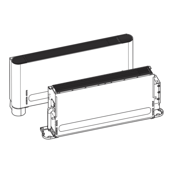
Informationen Bedienungsanleitung Code Definition Modus Drehzahlregelung falsch eingestellt Motor ohne Verpolungsschutz Tab. 12 Informationen Bedienungsanleitung 10.1 Systemübersicht 10.3 Wartung WARNUNG Stromschlag. ▶ Vor dem Reinigen des Klimageräts sicherstellen, dass es stromlos ist. ▶ Verdrahtung auf Unversehrtheit und einwandfreien Anschluss über- prüfen. - Page 25 Informationen Bedienungsanleitung 3. Filterhalter ausklappen und Filter herausziehen. 0010021961-002 Bild 31 Reinigen des Lufteintritts mit dem Staubsauger 0010021962-002 Bild 32 Reinigen des Lufteintritts mit sauberem Wasser HINWEIS 0010053231-001 ▶ Luftfilter nicht unter direkter Sonneneinstrahlung oder mit Feuer Bild 29 Gerät mit Schrank trocknen.
- Page 26 Informationen Bedienungsanleitung Wartung nach längeren Stillstandszeiten 2. Kondensatwannenbaugruppe nach unten herausnehmen. ▶ Die Ein- und Austrittsöffnungen der Innen- und Außeneinheiten über- prüfen und alle eventuellen Verstopfungen beseitigen. ▶ Luftfilter und Gehäuse der Einheit reinigen. Luftfilter vor der Inbe- triebnahme wieder einbauen. ▶...
- Page 27 Informationen Bedienungsanleitung Wartung von Motor und Laufrad HINWEIS 1. Auf die Arretierung des oberen Laufradgehäuses drücken und das untere Laufradgehäuse um ca. 30 Grad um die Vorderkante des un- Wenn Sie nicht sicher sind, ob eine Störung vorliegt, konsultieren Sie teren Laufradgehäuses drehen.
-
Page 28: Umweltschutz Und Entsorgung
Verkleidungen infolge der Temperaturänderung erzeugt. Das Umweltschutz und Entsorgung Geräusch verschwindet, sobald die Einheit normal läuft. Der Umweltschutz ist ein Unternehmensgrundsatz der Bosch-Gruppe. Symptom 9: Nur Wechsel von Kühl-/Heizbetrieb in ausschließlichen Qualität der Produkte, Wirtschaftlichkeit und Umweltschutz sind für uns Ventilatorbetrieb gleichrangige Ziele. - Page 29 Anfrage bereitgestellt. Sie können sich unter der folgenden Anschrift an unseren Datenschutzbeauftragten wenden: Datenschutzbeauftragter, Information Security and Privacy (C/ISP), Robert Bosch GmbH, Post- fach 30 02 20, 70442 Stuttgart, DEUTSCHLAND. Sie haben das Recht, der auf Art. 6 Abs. 1 S. 1 f DSGVO beruhenden Ver- arbeitung Ihrer personenbezogenen Daten aus Gründen, die sich aus Ih-...
- Page 30 Anhang Anhang 13.1 Anschlussplan CN10 CN22 CN18 CN55 M1 M2 X1 X2 B1 B2 B3 D1 D2 0010052850-002 Bild 36 Anschlussplan Anschlussklemme für Kommunikationsleitung Anschlussklemme für Funktionsmodul-Adapterplatte Anschlussklemme für EIN/AUS-Fernsignal Reserviert Anschlussklemme für Alarmsignal Netzkabelanschluss und Erdungsklemme Wasserstandsschalter Kondensatpumpe Displayeinheit [10] Elektronisches Expansionsventil T2A Temperaturfühler Wärmetauscher-Eingang T2B Temperaturfühler Wärmetauscher-Ausgang...
- Page 31 Table of contents 10.3.1 Maintenance of conventional parts and Table of contents components ........54 10.4 Symptoms that are not faults.
- Page 32 Explanation of symbols and safety instructions ▶ Mount the air conditioner in a place that is sturdy enough to bear its Explanation of symbols and safety instructions weight. If the base is not secured properly, the air conditioner may drop leading to damages and injuries. Explanation of symbols ▶...
- Page 33 Product Information ▶ When mounting the indoor and outdoor units, make sure the power ▶ The air outlet must not be directed at any human body as it is not cord is installed at a distance of at least 1 m away from any TV or radio conducive to the person's health when exposed to moving cold/hot to prevent noise or interference.
-
Page 34: Before Installation
Accessories Accessories Verify that the air conditioner includes the following accessories: Name Quantity Appearance Purpose Installation and user manual This manual Insulation pipe Thermal insulation and anti-condensation effect of piping connections Brass nut For use in the installation works of connecting piping Base For some units Foot bolt... -
Page 35: Installation
Installation ▶ Choose a site that fully complies with the following conditions and user requirements to install the air conditioning unit: – Well ventilated. – Unobstructed airflow. – Strong enough to bear the weight of the indoor unit. – Away from direct exposure to the sun. –... -
Page 36: Refrigerant Piping Installation
Installation Dimensions 6.1.1 Dimensions of the unit body ΦE ΦF 0010053138-001 Fig. 43 External dimensions and size of air outlet opening (unit: mm) Connecting point of the refrigerant pipe (liquid side) Connecting point of the refrigerant pipe (gas side) Product Type AF2-F/FC 22-1 –... - Page 37 Installation 4. Insert the bundled piping and wiring from outside the room through the wall opening into the room. Be careful when laying the piping not NOTICE to damage it. Apply the appropriate tightening torque according to the installation conditions. Excessive torque will damage the socket cap. But the cap will 6.2.5 Piping installation not be tight if you apply insufficient torque which leads to leakages.
- Page 38 Installation Pipe outer ≤ 20 20 – 40 ≥ 40 diameter (mm) For the vacuum, make sure that the air and liquid cut-off valves of the Horizontal pipe outdoor unit are all closed (maintain the factory defaults). distance (m) Stand pipe 6.2.9 Refrigerant distance (m)
-
Page 39: Power Cord Connection
Installation ▶ When connecting to the power supply terminal, use the circular wiring terminal with the insulation casing. NOTICE ▶ Make sure all the connections in the piping system are properly sealed to prevent water leakages. Electrical wiring HWarnings ▶ All the supplied parts, materials and electrical works must comply with local regulations. - Page 40 Installation 6.4.2 Electrical wiring specifications Table 18 Indoor units electrical characteristics Abbreviations: NOTICE MCA Minimum Circuit Amps The connection cables have to follow the standards 60227 IEC 52 or EN MFA Maximum Fuse Amps 50525-2-11, as there might be higher voltages on these cables. They Indoor Fan Motor also have to be shielded so the communication is not be disturbed.
- Page 41 Installation ▶ Remove the cover by pulling it downwards. 0010053143-001 Fig. 53 • The indoor and outdoor units communicate via SuperLink (M1 M2). The connecting lead for this communication wire must come from the master outdoor unit. • The communication wiring between the indoor and outdoor units should connect one unit after another from the outdoor unit to the final indoor unit.
- Page 42 Installation ▶ The Super communication line of both outdoor and indoor units with the function of power-down control valve has a total length of up to 600m, supporting any topological connection. The figure below indicates the serial connection. CN23 IDU 1# IDU 10# ×...
- Page 43 Installation unit port with the downstream indoor unit port.Otherwise, ▶ When the indoor unit is powered uniformly, the Super Link communication faults will occur. communication line may not be with function of the power-down control valve of the indoor unit. At this time, the communication line only needs to be with a wire diameter of 2 x 0.75 mm .
- Page 44 Installation ▶ Use 1 wired controller to control multiple indoor units or 2 wired controllers (one master and one slave controller) to control multiple indoor units. X1 X2 X1 X2 0010047267-002 Fig. 59 Main control board One-control-one Main control board Two-control-one Two wired controllers can be used to control one indoor unit at the same time.
- Page 45 Test run Achieving centralized control of the indoor unit through D1/D2 communication CN18 The D1/D2 communication line can also be connected to the centralized controller to achieve centralized control of the indoor units, as shown in Fig. 61. D1 D2 D1 D2 D1 D2 3-(n-1)# IDU...
- Page 46 On-site configuration Test run Error Content Control the air conditioner for cooling or heating operation with a wire/ code remote controller, and operate it according to the instructions. If there is Reserved a fault, troubleshoot according to the manual. Abnormal communication between the main control board of indoor unit and the display board 7.2.1 Indoor unit...
- Page 47 On-site configuration Error Content code T2B (heat exchanger outlet temperature sensor) short circuit or open circuit Main control board EEPROM fault Indoor unit display control board EEPROM fault Locked (electronic lock) Model code not set Capacity code setting failure Capacity code setting error AHU kit fan control input signal dial setting error No address code detected Multiple motor faults...
-
Page 48: Troubleshooting Steps
Troubleshooting Defrosting operation (cooling and heating): Troubleshooting • In case of low outdoor temperature and high humidity, the heat exchanger of the outdoor unit may be covered with frost, which will Non-air Conditioner Fault reduce the heating capacity of the air conditioner. •... -
Page 49: Error Codes
Troubleshooting Faults that are not displayed Symptom Possible causes Troubleshooting steps The unit does not start A power blackout has occurred (the power to the premises Wait for the power to come back on. has been cut-off). The unit is powered off. Power on the unit. - Page 50 Troubleshooting Code Definition Pump 1 blocking protection Pump 2 blocking protection Water level switch alarm Rethermoelectric heating failure Preconditioning electric heater failure Humidifier failure The address code of the indoor unit is repeated Communication error between indoor and outdoor units Communication error between the main control board of the indoor unit and thefan driver board Communication error between the indoor unit and the controller Communication error between the indoor unit and the Wi-Fi Kit...
- Page 51 Troubleshooting Code Definition No address code detected Multiple motor failures IPM fan module overcurrent protection Phase current transient overcurrent protection Low bus voltage failure Excessive bus voltage failure The sampling value of the phase current is abnormal Motor does not match indoor machine model IPM does not match the indoor unit model Motor startup failure Motor blocking protection...
-
Page 52: System Overview
Informations Owners Manual Informations Owners Manual 10.1 System overview WARNING Material damage and risk of injury due to excessive pressure! ▶ Release the pressure before disassembly. NOTICE Notes on safety for the maintenance. ▶ Use a dry cloth to wipe the indoor unit and remote controller. ▶... - Page 53 Informations Owners Manual 3. Rotate the filter bracket and pull the filter out. 0010021961-002 Fig. 67 Cleaning the air intake using a vacuum cleaner 0010021962-002 Fig. 68 Cleaning the air intake using clean water NOTICE 0010053231-001 ▶ Do not dry the air filter in direct sunlight or with fire. Fig.
- Page 54 Informations Owners Manual 10.3.1 Maintenance of conventional parts and components 2. Remove the drain pan assembly in a downward direction. Drain pan maintenance Make sure there is no residual water before dismantling the drain pan. 1. Dismantle the top cover plate assembly. 0010053141-001 Fig.
-
Page 55: Symptoms That Are Not Faults
Informations Owners Manual 3. Remove the motor and wind wheel together. Symptom 1: The unit will not run • When the ON/OFF button on the remote controller is pressed, the unit does not immediately start running. Cause: To protect certain system components, the system start-up or re-start is intentionally delayed for up to 12 minutes under certain operating conditions. -
Page 56: Environmental Protection And Disposal
The operating mode of all indoor units must be the same. Environmental protection and disposal Environmental protection is a fundamental corporate strategy of the Bosch Group. The quality of our products, their economy and environmental safety are all of equal importance to us and all environmental protection legislation and regulations are strictly observed. - Page 57 Appendix Appendix 12.1 User wiring diagram CN10 CN22 CN18 CN55 M1 M2 X1 X2 B1 B2 B3 D1 D2 0010052850-002 Fig. 72 User wiring diagram Communication line terminal Function module adapter board terminal Remote ON/OFF signal terminal Reserved Alarm signal terminal Power cord and earth terminal Water level switch Drainage pump...
-
Page 58: Table Of Contents
Índice 10.1 Vista general del sistema......79 Índice 10.2 Funcionamiento del equipo..... . 79 10.3 Mantenimiento. -
Page 59: Explicación De Los Símbolos
Explicación de los símbolos e indicaciones de seguridad ▶ Asegurarse de que se hayan instalado las piezas y los accesorios Explicación de los símbolos e indicaciones de requeridos. El uso de piezas no especificadas puede causar un error seguridad del equipo así como una fuga de agua, una descarga de corriente y fuego. -
Page 60: Información Importante Para El Usuario
Explicación de los símbolos e indicaciones de seguridad ▶ Controlar el esquema de conexiones eléctricas, de las tuberías de tos avanzados (incluyendo niños). Por su propia seguridad no deben agua y de gas dentro de las paredes, del suelo y del techo antes de usar la unidad a no ser que sea supervisado o guiado por el personal proceder con la instalación. -
Page 61: Datos Sobre El Producto
Con la identificación CE se declara la conformidad del pro- ducto con todas las directivas legales aplicables en la UE que prevén la colocación de esta identificación. El texto completo de la declaración de conformidad está disponible en internet: www.bosch-industrial.com. Air Flux – 6721874910 (2024/05) -
Page 62: Accesorios
Accesorios Accesorios Verificar que el equipo incluya los siguientes accesorios: Nombre Canti- Apariencia Propósito Manual de instalación y de usuario 1 Este manual Aislamiento de tubo Aislamiento térmico y efecto anticondensación de las conexiones de las tuberías Tuerca de cobre Para usar en trabajos de instalación de tuberías de conexión Base Para algunas unidades... -
Page 63: Instalación
Instalación ▶ Elegir un lugar que cumpla enteramente con las siguientes condicio- horizontalmente y en una pared de la misma estancia que la unidad. La nes y con los requisitos del usuario para instalar la unidad de equipo: sonda se debería colocar a 100 mm sobre el suelo. –... -
Page 64: Dimensiones
Instalación Dimensiones 6.1.1 Dimensiones del cuerpo de la unidad ΦE ΦF 0010053138-001 Fig. 79 Dimensiones externas y de la abertura de la salida de aire (unidad: mm) Punto de conexión del tubo de refrigerante (lado del líquido) Punto de conexión del tubo de refrigerante (lado del gas) Tipo de producto AF2-F/FC 22-1 –... -
Page 65: Instalación De Los Tubos
Instalación 2. Si las tuberías necesitan pasar por paredes, taladrar el orificio en la Diámetro Par de apriete Diámetro de Orificio abocardado pared y utilizar accesorios como revestimientos y cubiertas para la externo Ø [ de ajuste [Nm] orificio ab- apertura. -
Page 66: Prueba De Estanqueidad
Instalación ▶ En caso de que se llene nitrógeno durante la soldadura, la presión ▶ Para el sistema utilizado en invierno para la calefacción en zonas de debe reducirse a 0,02 MPa, utilizando la válvula de reducción de pre- frío intenso, el espesor del tubo de aislamiento se incrementará. Para sión. -
Page 67: Cableado Eléctrico
Instalación ▶ El circuito de alimentación eléctrica externo del dispositivo debe incluir una toma de tierra. La toma de tierra del cable de corriente, que conecta la unidad interior, debe estar conectado de manera segura a la toma de tierra de la alimentación eléctrica externa. ▶... -
Page 68: Características De Cableado Eléctrico
Instalación ▶ Utilizar un cable que cumpla con las especificaciones y conectar el cable de corriente firmemente. A fin de evitar que se retire el cable por fuerzas externas, asegurarse que esté fijamente asegurado. ▶ Utilizar, al menos, una sección de 1 mm del cable de alimentación BVV con aislamiento de PVC con tres hilos de cobre. -
Page 69: Cableado De Comunicación
Instalación • Las unidades interiores y exteriores se intercomunican mediante Corriente nominal Superficie de sección nominal (mm SuperLink (M1 M2). La conexión de este cable de comunicación del aparato (A) Cables flexibles Cables para cableado debe provenir de la unidad exterior maestra. fijo •... - Page 70 Instalación ▶ La línea de comunicación Super Link de las unidades interiores y exteriores con la función de la válvula de control de apagado tiene una longitud total de 600 m, y es compatible con cualquier topología de conexión. La figura de abajo indica la conexión de serie. CN23 IDU 1# IDU 10#...
- Page 71 Instalación interior aguas arriba con l puerto de la unidad interior aguas abajo. De lo ATENCIÓN contrario se producirá un fallo de comunicación. Si la distancia total es ≤200 m y el número total de unidades interiores El repetidor es un accesorio opcional. Si lo desea, póngase en contacto es ≤10, y la unidad exterior principal suministra electricidad a la válvula de control.
- Page 72 Instalación ▶ Utilizar 1 controlador con cable para controlar múltiples unidades interiores o 2 controladores con cable (un controlador maestro y uno esclavo) para controlar múltiples unidades interiores. X1 X2 X1 X2 0010047267-002 Fig. 95 Panel de mando principal Uno-control-uno Panel de mando principal Dos-control-uno Se pueden utilizar al mismo tiempo dos controladores cableados para...
- Page 73 Instalación Obtener el control centralizado de la unidad interior a través de la comunicación D1/D2 CN18 El conducto ramal de la comunicación D1/D2 también se puede conec- tar al regulador centralizado para obtener el control centralizado de las unidades interiores, como se muestra en la fig. 97. D1 D2 D1 D2 D1 D2...
-
Page 74: Manejo De Los Puntos De Conexión De Cableado Eléctrico
Prueba de funcionamiento 6.4.4 Manejo de los puntos de conexión de cableado eléctrico Configuración in situ ▶ Una vez que el cableado y las conexiones hayan sido realizadas, utili- zar las bridas para cables para asegurar el cableado correctamente, Códigos y definiciones de error de manera que la unión no pueda ser separada por fuerzas externas. -
Page 75: Eliminación De Fallos
Configuración in situ Códi- Contenido Códi- Contenido go de go de error error Fallo del panel de control del sensor Error ajuste modo de control velocidad Fallo sensor PM2.5 Protección pérdida fase motor Fallo sensor CO2 Tab. 34 Códigos de error Fallo sensor formaldehído Códi- Contenido... -
Page 76: Errores Que No Se Visualizan
Eliminación de fallos (Esta función no está disponible si se ha seleccionado un panel de Fenómeno normal en lugar de un fallo del equipo otro proveedor) Si se producen los fenómenos siguientes durante el funcionamiento del equipo, son algo normal y se pueden eliminar siguiendo los pasos indica- dos abajo o bien no se requiere ninguna medida especial. -
Page 77: Códigos De Error
Eliminación de fallos Síntoma Posibles causas Pasos de eliminación de fallos Bajo efecto de refrigera- La luz solar se encuentra directamente en la unidad. Cerrar las persianas para proteger la unidad contra la radiaci- ción ón solar directa. La habitación contiene varias fuentes de calor como orden- Desconectar algunas de los ordenadores durante la parte adores o refrigeradores. - Page 78 Eliminación de fallos Código Definición Error de comunicación entre el panel de control principal de la unidad interior y la tarjeta de expansión de funcionamiento 1 Error de comunicación entre la placa principal de la unidad interior y la tarjeta de expansión de funcionamiento 2 Error de comunicación entre la placa principal de la unidad interior y la placa de conversión La temperatura del aire de entrada de la unidad interior en el funcionamiento de la calefacción es demasiado baja La temperatura del aire de entrada de la unidad interior en el funcionamiento de la calefacción es demasiado alta...
-
Page 79: Manual De Información Del Usuario
Manual de información del usuario Manual de información del usuario 10.1 Vista general del sistema ADVERTENCIA Daños materiales y riesgos de lesión debido a una presión excesiva. ▶ Desconectar la presión antes de proceder con el desmontaje. AVISO Notas en cuanto a la seguridad por el mantenimiento. ▶... - Page 80 Manual de información del usuario 3. Girar el soporte del filtro y sacar el filtro. 0010021961-002 Fig. 103 Limpiar la entrada de aire con una aspiradora 0010021962-002 Fig. 104 Limpiar la entrada de aire usando agua limpia AVISO 0010053231-001 ▶ No exponer el filtro de aire directamente al sol o al fuego para secarlo. Fig.
-
Page 81: Mantenimiento De Piezas Y Componentes Convencionales
Manual de información del usuario ▶ Limpiar la carcasa de la unidad y el filtro. Reinstalar el filtro antes de 2. Retirar el panel de la bandeja de descarga hacia abajo. activar la unidad. ▶ Conectar la corriente 12 horas antes de reiniciar la unidad para ase- gurar un funcionamiento suave. -
Page 82: Síntomas Que No Son Fallos
Manual de información del usuario Mantenimiento del motor y de las aspas del ventilador AVISO 1. Presionar la pestaña de la carcasa del propulsor superior y girar la carcasa del propulsor inferior alrededor de la esquina frontal de la En caso de no estar seguro si consta un error, contactar con el servicio carcasa del propulsor inferior alrededor de 30 grados. -
Page 83: Protección Del Medio Ambiente Y Eliminación De Residuos
La protección del medio ambiente es uno de los principios empresaria- tilación. Cuando la temperatura ambiente aumenta (en el modo les del grupo Bosch. Refrigeración) o disminuye (en el modo Calefacción) un valor deter- La calidad de los productos, la productividad y la protección del medio minado, el compresor se reinicia y se reanuda la refrigeración o la... -
Page 84: Aviso De Protección De Datos
Bosch. En algunos casos, pero solo si se asegura una protección de datos adecuada, se podrían transferir datos persona- les a receptores ubicados fuera del Espacio Económico Europeo. -
Page 85: Anexo
Anexo Anexo 13.1 Esquema de conexiones eléctricas CN10 CN22 CN18 CN55 M1 M2 X1 X2 B1 B2 B3 D1 D2 0010052850-002 Fig. 108 Esquema de conexiones eléctricas Borne de conexión de la línea de comunicación Borne de conexión de la placa adaptadora del módulo de función Borne de conexión de señal ON/OFF remota Reservado Borne de conexión de la señal de alarma... - Page 86 Sommaire 10.1 Aperçu du système ......107 Sommaire 10.2 Commandes et performance du climatiseur ..107 10.3 Maintenance.
-
Page 87: Explication Des Symboles Et Mesures De Sécurité
Explication des symboles et mesures de sécurité ▶ Vérifier que les pièces et accessoires nécessaires sont installés. L’uti- Explication des symboles et mesures de sécurité lisation de pièces non spécifiées peut causer un dysfonctionnement ou une chute du climatiseur, ainsi qu’une fuite d’eau, un choc élec- Explications des symboles trique ou un incendie. -
Page 88: Informations Importantes Pour L'utilisateur
Explication des symboles et mesures de sécurité ▶ Contrôler l’alimentation électrique avant l’installation. L’alimentation 1.2.1 Informations importantes pour l'utilisateur électrique doit être mise à la terre de manière fiable et dans le res- • Si vous n'êtes pas sûr de savoir procéder à l'opération de l'unité, pect des normes électriques locales, régionales et nationales. -
Page 89: Informations Sur Le Produit
Le marquage CE prouve la conformité du produit avec toutes les prescriptions européennes légales, qui prévoient la pose de ce marquage. Le texte complet de la déclaration de conformité est disponible sur Internet : www.bosch-industrial.com. Air Flux – 6721874910 (2024/05) -
Page 90: Accessoires
Accessoires Accessoires Vérifier que le climatiseur inclut les accessoires suivants : Désignation Quantité Apparence Usage Notice d’installation et d’utilisa- Cette notice tion Tube isolant Isolation thermique et protection anti-condensation des raccordements frigorifiques Écrou en laiton pour le raccordement des tuyauteries frigorifiques Base Pour certaines unités Boulon de pied... -
Page 91: Choix De L'emplacement D'installation
Choix de l’emplacement d’installation Choix de l’emplacement d’installation ▶ L’unité intérieure ne doit pas être installée trop proche du plafond, et elle doit être placée de niveau ou à une inclinaison inférieure à 1° vers le côté évacuation. (Pour les modèles sans pompes d’évacuation, une inclinaison de 1/100 vers le côté... -
Page 92: Installation
Installation Installation AVIS Veiller à ce que seuls les composants spécifiés soient utilisés pour l’ins- ▶ Installer le climatiseur à un emplacement suffisamment solide pour tallation. supporter le poids de l’unité. L’unité risque de tomber et d’entraîner des dommages corporels si l’emplacement choisi n’est pas assez solide. -
Page 93: Installation Des Tubes De Réfrigérant
Installation Installation des tubes de réfrigérant ▶ En cas de fuite de réfrigérant pendant l’installation, veiller à ventiler complètement la pièce. 6.2.1 Contraintes de longueur et de différence de niveau pour les ▶ Utiliser deux clés pour installer ou démonter les tubes : une clé raccordements de tube des unités intérieures et exté- simple et une clé... -
Page 94: Test D'étanchéité À L'air
Installation ▶ Avant d’installer l'écrou sur le dudgeon, appliquer de l’huile réfrigé- Diamètre exté- ≤ 20 20 – 40 ≥ 40 rante sur le dudgeon (à l’intérieur et à l’extérieur), puis le faire tour- rieur du tube ner trois ou quatre fois avant de serrer l'écrou. (mm) Longueur du tube horizontal... -
Page 95: Tirage Au Vide
Installation 6.2.8 Tirage au vide ▶ Utiliser le tuyau souple d’évacuation joint pour le raccorder au collec- teur d’évacuation d’eau et au tube PVC, et fixer les deux extrémités ▶ Faire le vide dans le système conformément aux instructions de la du tuyau souple d’évacuation à... -
Page 96: Caractéristiques Techniques Du Câblage Électrique
Installation ▶ Lors du raccordement à la borne d’alimentation électrique, utiliser 6.4.2 Caractéristiques techniques du câblage électrique une cosse à oeillet isolée. AVIS Les câbles de connexion doivent respecter la norme EN 50525- 2- 11, car il peut y avoir des tensions supérieures sur ces câbles. Ils doivent également être blindés pour ne pas perturber la communication. -
Page 97: Câblage De Communication
Installation ▶ Démonter le couvercle en le tirant vers le bas. Tab. 44 Caractéristiques électriques des unités intérieures Abréviations: MCA Minimum Circuit Amps (Intensité max absorbée) MFA Maximum Fuse Amps (Calibre fusible conseillé) Moteur du ventilateur intérieur Puissance nominale du moteur FLA Intensité... - Page 98 Installation ▶ Raccorder la ligne de communication au bornier « CN10 » sur la carte ▶ La ligne de communication Super Link des unités extérieure et inté- mère conformément aux marquages « M1 » et « M2 ». Comme la rieure avec la fonction d’arrêt de la vanne de régulation a une lon- communication Super Link est une communication sans polarité, gueur totale de plus de 600 m, supportant toute connexion...
- Page 99 Installation rieure et celle en aval de l’unité intérieure. Sinon, cela entraînerait des PRUDENCE erreurs de communication. Si la distance totale est ≤200 m et que le nombre total des unités inté- Le répéteur est un accessoire optionnel. Contacter son revendeur local rieures est ≤10, l’unité...
- Page 100 Installation ▶ Utiliser 1 commande filaire pour contrôler plusieurs unités inté- rieures ou 2 commandes filaires (une commande maître et une com- mande esclave) pour contrôler plusieurs unités intérieures. X1 X2 X1 X2 0010047267-002 Fig. 131 Circuit imprimé principal Un contrôle un Circuit imprimé...
- Page 101 Installation Réalisation d’un contrôle centralisé de l’unité intérieure par le biais de la communication D1/D2 CN18 La ligne de communication D1/D2 peut également être connectée à l’appareil de régulation centralisé afin d’obtenir un contrôle centralisé des unités intérieures, comme illustré dans la fig. 133. D1 D2 D1 D2 D1 D2...
-
Page 102: Traitement Des Points De Raccordement Du Câblage Électrique
Cycle d’essai 6.4.4 Traitement des points de raccordement du câblage élec- trique ▶ Une fois le câblage et les raccordements terminés, utiliser des Une fois l’alimentation raccordée, le climatiseur dispose d’une fonction attaches de câbles pour sécuriser correctement le câblage, de de protection qui retarde le démarrage du compresseur de 3 minutes si manière à... -
Page 103: Elimination Des Défauts
Elimination des défauts Code Contenu Code Contenu d’erre d’erre Défaut de communication entre la carte de commande princi- Aucun code d’adresse détecté pale de l’unité intérieure et la deuxième carte d’extension de Plusieurs défauts du moteur fonction Protection contre les surintensités de l’IPM (module de com- Défaut de communication entre la carte de commande princi- mande du ventilateur) pale et la carte de l’adaptateur de l’unité... -
Page 104: Défauts Non Affichés
Elimination des défauts • Le cas échéant, le climatiseur s’arrêtera de chauffer, dégivrera auto- • Si l’humidité est très élevée, le climatiseur empêchera la formation matiquement puis reprendra le chauffage après le dégivrage. d’eau de condensation en ajustant l’angle du déflecteur d’air et la vitesse de rotation du ventilateur afin d’éviter que de l’eau de conden- •... -
Page 105: Codes D'erreur
Elimination des défauts Symptôme Causes possibles Mesures de dépannage L’unité démarre ou Mandater un technicien spécialisé pour contrôler les points suivants : s’arrête fréquemment • Quantité de réfrigérant excessive ou insuffisante. • Pas de gaz dans le circuit de réfrigérant. •... - Page 106 Elimination des défauts Code Définition Défaut de communication entre la carte de commande principale de l’unité intérieure et la carte de l’unité d’entraînement du ventilateur Défaut de communication entre l’unité intérieure et l’appareil de régulation Défaut de communication entre l’unité intérieure et le kit Wi-Fi Défaut de communication entre la carte de commande principale de l’unité...
-
Page 107: Informations Du Manuel De L'utilisateur
Informations du manuel de l’utilisateur Code Définition La valeur d’échantillonnage du courant de phase est anormale Le moteur ne correspond pas au modèle de l’unité intérieure L’IPM ne correspond pas au modèle de l’unité intérieure Erreur de démarrage du moteur Protection contre le blocage du moteur Erreur de réglage du mode de régulation du régime Absence de protection de phase du moteur... - Page 108 Informations du manuel de l’utilisateur 1. Démonter le couvercle (pour les unités avec armoire). 2. Retirer les deux vis. 3. Tourner le support de filtre et retirer le filtre. 0010021961-002 Fig. 139 Nettoyage de l’entrée d’air avec un aspirateur 0010021962-002 Fig.
-
Page 109: 10.3.1 Maintenance Des Pièces Et Composants Traditionnels
Informations du manuel de l’utilisateur ▶ Mettre l’unité sous tension au moins 12 heures avant de l’utiliser afin 2. Retirer le module de bac d’évacuation en le tirant vers le bas. de s’assurer qu’elle fonctionne correctement. Dès que l’alimentation est établie, l’affichage de la commande à distance s’allume. 10.3.1 Maintenance des pièces et composants traditionnels Maintenance du bac d’évacuation S’assurer qu’il n’y a pas d’eau résiduelle avant de démonter le bac d’éva-... -
Page 110: Symptômes N'indiquant Pas Des Défauts
Informations du manuel de l’utilisateur Maintenance du moteur et de la roue à ailettes AVIS 1. Appuyer sur la boucle du boîtier de l’hélice supérieure et faire pivoter le boîtier de l’hélice inférieure autour du bord avant du boîtier de Si vous n’êtes pas sûr de savoir si un défaut s’est produit ou non, contac- l’hélice inférieure de 30 degrés environ. -
Page 111: Protection De L'environnement Et Recyclage
La protection de l’environnement est un principe de base du groupe ment de température. Le son disparaît lorsque l’unité fonctionne nor- Bosch. malement. Nous accordons une importance égale à la qualité de nos produits, à leur rentabilité... -
Page 112: 12 Déclaration De Protection Des Données
à des prestataires de service externes et/ou à des entreprises affiliées à Bosch. Dans certains cas, mais uniquement si une protection des données appropriée est assurée, les données à caractère personnel peuvent être transférées à... -
Page 113: Annexes
Annexes Annexes 13.1 Schéma de câblage utilisateur CN10 CN22 CN18 CN55 M1 M2 X1 X2 B1 B2 B3 D1 D2 0010052850-002 Fig. 144 Schéma de câblage utilisateur Borne de la ligne de communication Borne de la carte d’adaptateur du module de fonction Borne du signal Marche/Arrêt à... - Page 114 Indice 10.2 Operazioni e prestazioni del condizionatore ..135 Indice 10.3 Manutenzione....... . 135 10.3.1 Manutenzione delle parti e dei componenti Significato dei simboli e avvertenze di sicurezza .
-
Page 115: Significato Dei Simboli E Avvertenze Di Sicurezza
Significato dei simboli e avvertenze di sicurezza ▶ Montare il condizionatore in un posto sufficientemente robusto da Significato dei simboli e avvertenze di sicurezza reggerne il peso. Se non è fissato correttamente, il condizionatore può cadere causando danni e lesioni. Significato dei simboli ▶... -
Page 116: Informazioni Importanti Per L'utente
Significato dei simboli e avvertenze di sicurezza ▶ Installare la tubatura di scarico dell'acqua seguendo gli step descritti Avvertenze nel presente manuale e accertare che lo scarico d'acqua sia regolare ▶ Questa unità è composta da componenti elettrici e parti calde (peri- e la tubatura sia adeguatamente isolata per evitare la condensa. -
Page 117: Descrizione Del Prodotto
Con la marcatura CE si dichiara la conformità del prodotto con tutte le disposizione di legge UE da utilizzare, che prevede l'applicazione di questo marchio. Il testo completo della dichiarazione di conformità è disponibile su Inter- net: www.bosch-industrial.com. Air Flux – 6721874910 (2024/05) -
Page 118: Accessori
Accessori Accessori Verificare che il condizionatore comprenda i seguenti accessori: Nome Quantità Aspetto Scopo Manuale installazione ed uso Il presente manuale Tubo di isolamento Isolamento termico ed effetto anticondensa dei collegamenti delle tuba- ture Dado in ottone Da utilizzare nell'installazione della tubatura di collegamento Base Per alcune unità... -
Page 119: Selezione Di Un Sito D'installazione
Selezione di un sito d'installazione Selezione di un sito d'installazione ▶ L'unità interna non deve essere installata vicino al soffitto e deve essere mantenuta in orizzontale o con un'inclinazione di massimo 1° verso il lato dello scarico. (Per i modelli senza le pompe di scarico, è necessaria un'inclinazione di 1/100 verso il lato dello scarico e non è... -
Page 120: Installazione
Installazione Installazione Verificare che soltanto i componenti specificati siano utilizzati per l'installazione. AVVISO ▶ Installare il condizionatore in un punto abbastanza resistente da reg- gere il peso dell'unità. In caso contrario, l'unità può cadere e causare danni alle persone. ▶ Eseguire i lavori previsti per l'installazione per evitare danni causati da venti forti o terremoti. -
Page 121: Installazione Del Tubo Del Refrigerante
Installazione Installazione del tubo del refrigerante ▶ In caso di perdita di refrigerante durante l'installazione, aerare com- pletamente l'area. 6.2.1 Lunghezza e requisiti di differenza di livello per i collega- ▶ Utilizzare due chiavi per installare o smantellare il tubo, una chiave menti della tubatura dell'unità... -
Page 122: Test Di Tenuta All'aria
Installazione ▶ Prima di installare il relativo tappo sulla presa del tubo, applicare olio Diametro ester- ≤ 20 20 – 40 ≥ 40 refrigerante sulla presa (all'interno e all'esterno) e ruotare tre o quat- no tubo (mm) tro volte prima di serrare il tappo. Distanza tubo orizzontale (m) Distanza tubo... -
Page 123: Vuoto
Installazione 6.2.8 Vuoto ▶ Collegare il tubo flessibile di scarico fornito a corredo allo scarico della vaschetta di raccolta dell'acqua e al tubo PVC e fissare le due ▶ Creare un vuoto nell'impianto secondo le istruzioni del manuale di estremità del tubo flessibile di scarico con una fascetta stringicavi. installazione dell'unità... -
Page 124: Specifiche Di Cablaggio Elettrico
Installazione ▶ Per collegare il terminale di alimentazione elettrica, utilizzare il termi- 6.4.2 Specifiche di cablaggio elettrico nale di cablaggio circolare con il rivestimento isolante. AVVISO I cavi di collegamento devono essere conformi agli standard 60227 IEC 52 o EN 50525-2-11, poiché potrebbero essere presenti tensioni più elevate in questi cavi. -
Page 125: Cablaggio Di Comunicazione
Installazione ▶ Rimuovere la copertura tirandola verso il basso. Tab. 57 Caratteristiche elettriche dell'unità interna Abbreviazione: MCA Amp circuito minimo MFA Amp fusibile massimo Motore ventola interno Uscita nominale motore FLA Amp a pieno carico ▶ Selezionare i singoli diametri minimi del filo conduttore per ogni unità in base alla tabella 58. - Page 126 Installazione ▶ Collegare la linea di comunicazione al blocco del morsetto per colle- ▶ La linea di comunicazione Super Link di entrambe le unità interna ed gamento "CN10" sulla scheda madre seguendo i simboli "M1" e "M2". esterna con la funzione della valvola di regolazione per alimentazione Poiché...
- Page 127 Installazione monte con l'unità interna a valle. In caso contrario, potrebbero verificarsi ATTENZIONE disfunzioni di comunicazione. Nel caso in cui la distanza totale sia ≤200 m e il numero totale di unità Il ripetitore è un accessorio opzionale. Se richiesto, contattare il proprio interne sia ≤10, l'unità...
- Page 128 Installazione ▶ Utilizzare 1 termoregolatore cablato per controllare multiple unità interne o 2 termoregolatori cablati (uno master e uno slave) per con- trollare multiple unità interne . X1 X2 X1 X2 0010047267-002 Fig. 167 Scheda di comando principale Uno-controlla-uno Scheda di comando principale Due-controllano-uno È...
- Page 129 Installazione Realizzazione della termoregolazione centralizzata dell'unità interna per mezzo della comunicazione D1/D2 CN18 La linea di comunicazione D1/D2 può anche essere collegata al termore- golatore centralizzato per la gestione a livello centrale delle unità interne, come illustrato in fig. 169. D1 D2 D1 D2 D1 D2...
-
Page 130: Movimentazione Dei Punti Di Collegamento Di Cablaggio Elettrico
Esecuzione del test 6.4.4 Movimentazione dei punti di collegamento di cablaggio Configurazione elettrico ▶ Dopo avere effettuato i collegamenti, con le fascette stringitubi fis- Codici di errore e definizioni sare adeguatamente i cavi in modo che il collegamento non possa essere staccato da una forza esterna. -
Page 131: Indice
Configurazione Codi- Indice Codi- Indice ce di ce di errore errore Temperatura dell'aria in ingresso troppo alta dell'unità interna Mancato avviamento del motore nella cella frigorifera Protezione da stallo del motore Allarme di sovratemperatura e di sovraumidità Errore di impostazione della modalità di controllo della veloci- Disfunzione scheda controllo sensore tà... -
Page 132: Disfunzioni Non Visualizzate
Risoluzione dei problemi Funzione anticondensa: Fenomeno normale rispetto a un guasto del condizionatore • L'unità interna identifica l'ambiente di funzionamento. In caso si verifichino i seguenti fenomeni durante l'utilizzo del condizio- natore, ciò è normale e possono essere eliminati seguendo i passaggi •... -
Page 133: Codici Di Errore
Risoluzione dei problemi Sintomo Cause possibili Step di risoluzione dei problemi L'unità si avvia o si arres- Rivolgersi a un tecnico professionista per controllare quanto segue: ta frequentemente • Refrigerante in eccesso o in difetto. • Mancanza di gas nel circuito del refrigerante. •... - Page 134 Risoluzione dei problemi Codice Definizione Errore di comunicazione tra l'unità interna e il termoregolatore Errore di comunicazione tra l'unità interna e il kit Wi-Fi Errore di comunicazione tra la scheda di controllo principale dell'unità interna e la scheda del display Errore di comunicazione tra il kit AHU slave e l'h Quantità...
-
Page 135: Informazioni Manuale Dell'utente
Informazioni Manuale dell'utente Codice Definizione Guasto avviamento motore Protezione blocco motore La modalità di controllo della velocità è impostata in modo errato Protezione mancanza di fase motore Tab. 64 Informazioni Manuale dell'utente 10.1 Panoramica del sistema 10.3 Manutenzione AVVERTENZA Scossa elettrica. ▶... - Page 136 Informazioni Manuale dell'utente 3. Ruotare la staffa del filtro e tirare fuori il filtro. 0010021961-002 Fig. 175 Pulizia della presa d'aria con un aspirapolvere 0010021962-002 Fig. 176 Pulizia della presa d'aria con acqua pulita AVVISO 0010053231-001 ▶ Non asciugare il filtro dell'aria alla luce solare diretta o vicino al fuoco. Fig.
-
Page 137: 10.3.1 Manutenzione Delle Parti E Dei Componenti Tradizionali
Informazioni Manuale dell'utente Manutenzione dopo un periodo di inutilizzo prolungato 2. Rimuovere il gruppo di montaggio del contenitore di drenaggio verso il basso. ▶ Controllare e rimuovere ciò che potrebbe ostruire gli sfiati di entrata e uscita dell'unità interna ed esterna. ▶... -
Page 138: Problematiche Che Non Indicano Guasti
Informazioni Manuale dell'utente Manutenzione del motore e della girante AVVISO 1. Premere la linguetta dell'alloggiamento del propulsore superiore e ruotare l'alloggiamento del propulsore inferiore intorno al bordo In caso di incertezza sul verificarsi di un guasto, contattare il fornitore o anteriore dell'alloggiamento del propulsore inferiore di circa 30 il tecnico della manutenzione. -
Page 139: Protezione Ambientale E Smaltimento
La protezione dell'ambiente è un principio fondamentale per il gruppo arresta automaticamente e si passa alla modalità ventilatore. Quando Bosch . la temperatura aria ambiente aumenta (nella modalità raffresca- La qualità dei prodotti, il risparmio e la tutela dell'ambiente sono per noi mento) o diminuisce (nella modalità... -
Page 140: Etichettatura Ambientale Degli Imballaggi
Plastica grammazione servizi hotline e data hosting possiamo commissionare e trasferire dati a fornitori di servizi esterni e/o aziende affiliate a Bosch. Talvolta, ma soltanto con adeguata garanzia di tutela, i dati personali potrebbero essere trasferiti a destinatari non ubicati nello Spazio Econo-... -
Page 141: Allegato
Allegato Allegato 13.1 Schema elettrico utente CN10 CN22 CN18 CN55 M1 M2 X1 X2 B1 B2 B3 D1 D2 0010052850-002 Fig. 180 Schema elettrico utente Morsetto per collegamento della linea di comunicazione Morsetto per collegamento della scheda adattatore del modulo di funzione Morsetto per collegamento del segnale ON/OFF remoto Riservato... - Page 142 Spis treści 10.2 Funkcje i zakresy pracy klimatyzatora ... . 162 Spis treści 10.3 Konserwacja....... . . 163 10.3.1 Konserwacja standardowych części i Objaśnienie symboli i wskazówki dotyczące komponentów .
-
Page 143: Bezpieczeństwa
Objaśnienie symboli i wskazówki dotyczące bezpieczeństwa ▶ Upewnić się, że zamontowane są wymagane części i wyposażenie Objaśnienie symboli i wskazówki dotyczące dodatkowe. Stosowanie nieodpowiednich części może spowodować bezpieczeństwa usterkę lub upadek klimatyzatora lub wyciek wody, porażenie prądem elektrycznym lub pożar. Objaśnienie symboli ▶... -
Page 144: Ważne Informacje Dla Użytkownika
Objaśnienie symboli i wskazówki dotyczące bezpieczeństwa ▶ Przed montażem sprawdzić układ kabli elektrycznych, rur niewystarczające doświadczenie oraz/lub niewystarczającą wiedzę. hydraulicznych i gazowych w ścianie. Nie należy wiercić otworów bez Ze względów bezpieczeństwa takie osoby muszą przez cały czas konsultacji z użytkownikiem, szczególnie w przypadku ukrytych znajdować... -
Page 145: Informacje O Produkcie
Konstrukcja i charakterystyka robocza tego wyrobu spełniają wymagania europejskie i krajowe. Oznakowanie CE wskazuje na zgodność produktu z wszelkimi obowiązującymi przepisami prawnymi UE, przewidującymi umieszczenie oznakowania CE na produkcie. Pełny tekst deklaracji zgodności UE dostępny jest w internecie: www.bosch-industrial.com. Air Flux – 6721874910 (2024/05) -
Page 146: Osprzęt Dodatkowy
Osprzęt dodatkowy Osprzęt dodatkowy Upewnić się, że klimatyzator posiada następujący osprzęt dodatkowy: Nazwa Ilość Wygląd Przeznaczenie Instrukcja montażu i obsługi Niniejsza instrukcja Rura izolacyjna Izolacja termiczna z efektem zapobiegania kondensacji przyłączy rurowych Mosiężna nakrętka Używana podczas montażu rur połączeniowych Podstawa Dotyczy niektórych jednostek Śruby stopowe Tab. -
Page 147: Wybór Miejsca Montażu
Wybór miejsca montażu Wybór miejsca montażu ▶ Jednostki wewnętrznej nie należy montować w pobliżu sufitu i należy ją wypoziomować lub pochylić o 1° w stronę odpływu. (W przypadku modeli bez pomp odpływowych wymagane jest pochylenie 1/100 w stronę odpływu, a jakiekolwiek pochylenie w stronę nieodpływową jest niedozwolone.) W przeciwnym razie może dojść... -
Page 148: Instalacja
Instalacja Instalacja Upewnić się, że do montażu używane są wyłącznie wymagane elementy. WSKAZÓWKA ▶ Zamontować klimatyzator w miejscu o wytrzymałości wystarczającej do utrzymania ciężaru jednostki. W przeciwnym razie może dojść do upadku jednostki, co może być przyczyną urazów. ▶ Wyszczególnione prace montażowe należy przeprowadzić tak, aby uniknąć... -
Page 149: Wymiary Rury Gazowej/Cieczy
Instalacja 6.1.2 Wymiary rury gazowej/cieczy ▶ Wszystkie rury cieczy i gazu muszą być prawidłowo izolowane, aby Rurka miedziana do uniknąć wycieków wody. Do izolacji rur gazu użyć materiałów do klimatyzatora izolacji termicznej, które są odporne na temperatury powyżej Ø [mm] 120 °C. -
Page 150: Próba Szczelności
Instalacja ▶ Przed montażem zaślepki należy nałożyć olej chłodniczy na Zewnętrzna ≤ 20 20 – 40 ≥ 40 końcówkę (wewnątrz i na zewnątrz), a następnie obrócić ją trzy lub średnica rury cztery razy przed dokręceniem zaślepki. (mm) Odległość rury w poziomie (m) Odległość... -
Page 151: Podciśnienie
Instalacja 6.2.8 Podciśnienie ▶ Użyć dołączonego przewodu odpływowego do podłączenia do rury PVC i wylotu zbiornika spustowego oraz spiąć dwa zakończenia ▶ Wytworzyć podciśnienie w układzie zgodnie z procedurą opisaną przewodu odpływowego opaską kablową. Następnie wcisnąć rurę w instrukcji montażu jednostki zewnętrznej. izolacji termicznej, tak aby została blisko połączona z głównym korpusem, po czym spiąć... -
Page 152: Specyfikacja Okablowania Elektrycznego
Instalacja ▶ Podczas podłączania do zacisku zasilania, użyć okrągłego zacisku 6.4.2 Specyfikacja okablowania elektrycznego z izolacją. WSKAZÓWKA Przewody łączące muszą spełniać normy 60227 IEC 52 lub EN 50525- 2-11, ponieważ mogą na nich występować wyższe napięcia. Przewody muszą również być ekranowane, aby zapobiec zakłóceniom komunikacyjnym. -
Page 153: Okablowanie Komunikacyjne
Instalacja ▶ Zdjąć pokrywę, ciągnąć ją w dół. Tab. 71 Specyfikacje elektryczne jednostek wewnętrznych Skróty: MCA Min. obciążenie obwodów MFA Maksymalna wielkość bezpiecznika Silnik wentylatora wewnętrznego Znamionowa moc silnika FLA Całkowity pobór prądu ▶ Minimalną średnicę przewodu należy dobrać osobno dla każdej jednostki w oparciu o Tabelę... - Page 154 Instalacja ▶ Podłączyć przewód komunikacyjny do bloku zacisków "CN10" na ▶ Przewód komunikacyjny Super Link jednostki zewnętrznej i płycie głównej zgodnie z oznaczeniami "M1" i "M2"; ponieważ wewnętrznej z funkcją zaworu regulacyjnego wyłączania ma komunikacja Super Link jest bez biegunów, nie jest wymagane całkowitą...
- Page 155 Instalacja ▶ W przypadku jednakowego zasilania jednostki wewnętrznej przewód ▶ Przewód komunikacyjny Super Link i powiązane jednostki komunikacyjny Super Link może nie działać z zaworem regulacyjnym zewnętrznej i wewnętrznej bez funkcji zaworu regulacyjnego wyłączania jednostki wewnętrznej. W takiej sytuacji przewód wyłączania ma całkowitą...
- Page 156 Instalacja Podłączanie przewodów komunikacyjnych X1/X2 Przewody komunikacyjne X1 i X2 są podłączane głównie do przewodowego sterownika regulacyjnego. Dostępne są konfiguracje X1 X2 D1 D2 D1 D2 D1 D2 "jeden sterownik do jednej jednostki wewnętrznej" oraz "jeden dwa sterowniki do jednej jednostki wewnętrznej". Łączna długość...
-
Page 157: Połączenia Okablowania Elektrycznego
Test działania Należy wybrać albo moduł funkcyjny 1 i 2 oddzielnie, albo oba moduły w 6.4.4 Połączenia okablowania elektrycznego tym samym czasie. ▶ Po wykonaniu okablowania i połączeń użyć opasek kablowych do zabezpieczenia okablowania, aby złącze nie mogło zostać rozłączone Płyty rozbudowy funkcji mogą... -
Page 158: Konfiguracja Lokalna
Konfiguracja lokalna Treść Konfiguracja lokalna błędu Zbyt niska temperatura powietrza wlotowego do jednostki Kody błędów i definicje wewnętrznej w pomieszczeniu ogrzewanym Treść Zbyt wysoka temperatura powietrza wlotowego do jednostki błędu wewnętrznej w pomieszczeniu chłodzonym Wyłącznik awaryjny Alarm nadmiernej temperatury i nadmiernej wilgotności Natychmiastowe wyłączenie z powodu wycieku czynnika Usterka płyty sterowania czujnika chłodniczego R32... -
Page 159: Rozwiązywanie Problemów
Rozwiązywanie problemów Funkcja ochrony: Treść • Po włączeniu wyłącznika głównego należy uruchomić system błędu natychmiast po zatrzymaniu pracy, a jednostka zewnętrzna Zabezpieczenie nadprądowe przed prądem chwilowym fazy przestanie pracować po około 4 minutach, ponieważ sprężarka nie Zbyt niskie napięcie szynoprzewodu może być... -
Page 160: Usterki, Które Nie Są Wyświetlane
Rozwiązywanie problemów Usterka Możliwe przyczyny Rozwiązanie problemu Tryb chłodzenia/grzania jest Dzieje się to automatycznie, gdy jednostka wewnętrzna osiągnie Sprężarka uruchomi się ponownie podczas pracy przełączany na tryb ustawioną temperaturę. automatycznie, aby wznowić chłodzenie samego nawiewu powietrza. lub grzanie, jeśli temperatura ulegnie zmianie. - Page 161 Rozwiązywanie problemów Definicja Wyłączenie awaryjne Wyciek czynnika chłodniczego, natychmiastowe wyłączenie Błąd jednostki zewnętrznej Po usterce podłączonego nowego wentylatora zostanie ona przekazana do głównej jednostki wewnętrznej (ustawienie połączenia szeregowego). Po usterce sprzężenia nawilżania jednostki wewnętrznej jest ona przekazywana do głównej jednostki wewnętrznej. Po usterce podłączonego nowego wentylatora zostanie ona przekazana do głównej jednostki wewnętrznej (ustawienie połączenia nieszeregowego).
-
Page 162: Informacje Instrukcji Obsługi
Informacje instrukcji obsługi Definicja Zwarcie lub odłączenie czujnika temperatury TA powietrza wylotowego Usterka czujnika wilgotności powietrza wylotowego Usterka czujnika wilgotności powietrza powrotnego Usterka czujnika (górnego) temperatury termometru mokrego Usterka czujnika (dolnego) temperatury termometru mokrego Awaria czujnika wycieku środka chłodniczego Zwarcie lub odłączenie czujnika temperatury T2A na wlocie wymiennika ciepła Zwarcie lub odłączenie czujnika temperatury T2 pośrodku wymiennika ciepła Zabezpieczenie przed nadmierną... -
Page 163: Konserwacja
Informacje instrukcji obsługi 3. Obrócić wspornik filtra i wyciągnąć filtr. WSKAZÓWKA Jednostka pracuje stabilnie w zakresie temperatur podanym w powyższej tabeli. Jeśli temperatura w pomieszczeniu wykracza poza podany zakres, jednostka może zatrzymać się i wyświetlić kod błędu. 10.3 Konserwacja OSTRZEŻENIE Ryzyko porażenia prądem elektrycznym. -
Page 164: Konserwacja Standardowych Części I Komponentów
Informacje instrukcji obsługi ▶ Włączyć zasilanie min. 12 godzin przed uruchomieniem urządzenia, aby zapewnić jego płynną pracę. Po włączeniu zasilania włączy się wyświetlacz sterownika zdalnego. 10.3.1 Konserwacja standardowych części i komponentów Konserwacja zbiornika spustowego Przed zdemontowaniem zbiornika spustowego należy upewnić się, że w jego wnętrzu nie pozostała woda. -
Page 165: Objawy, Które Nie Są Usterkami
Informacje instrukcji obsługi 2. Zdjąć podzespół tacy ociekowej, pociągając go w dół. Podczas wymiany silnika należy zapewnić, aby kierunek wylotu z silnika był pionowo ustawiony w linii z papierem zwróconym do wnętrza. Przednie i tylne punkty silnika należy stabilnie zamocować przy użyciu utwierdzonej struktury na środkowej belce. -
Page 166: Ochrona Środowiska I Utylizacja
• W czasie samooczyszczania przez ok. 10 minut mogą występować Ochrona środowiska to jedna z podstawowych zasad działalności grupy delikatne "kliknięcia" oznaczające, że jednostka zamarza. Takie Bosch. zjawisko jest normalne. Jakość produktów, ekonomiczność i ochrona środowiska stanowią dla nas cele równorzędne. Ściśle przestrzegane są ustawy i przepisy Objaw 8: Jednostka emituje niski hałas... -
Page 167: Informacja O Ochronie Danych Osobowych
Czynniki chłodnicze stanowią zagrożenie dla środowiska i należy je oddzielnie zbierać i utylizować. Informacja o ochronie danych osobowych My, Robert Bosch Sp. z o.o., ul. Jutrzenki 105, 02- 231 Warszawa, Polska, przetwarzamy informacje o wyrobach i wskazówki montażowe, dane techniczne i dotyczące połączeń, komunikacji, rejestracji wyrobów... -
Page 168: Załącznik
Załącznik Załącznik 13.1 Schemat połączeń dla użytkownika CN10 CN22 CN18 CN55 M1 M2 X1 X2 B1 B2 B3 D1 D2 0010052850-002 Rys. 216 Schemat połączeń dla użytkownika Zacisk przyłączeniowy przewodu komunikacyjnego Zacisk przyłączeniowy płyty adaptera modułu funkcyjnego Zacisk przyłączeniowy zdalnego sygnału wł./wył. Zarezerwowany Zacisk przyłączeniowy sygnału alarmowego Kabel zasilania i zacisk uziemienia... - Page 169 [da] Klimaapparaters formålsmæssige brug Indendørsenheden er beregnet til at blive installeret indvendigt i byg- ninger med forbindelse til udeenheden og andre systemkomponenter, f.eks. styringer. Udeenheden er beregnet til at blive installeret uden for bygninger med for- bindelse til indendørsenheden eller -enhederne samt andre systemkom- ponenter, f.eks.
- Page 170 [en] Intended use of air conditioners [fi] Ilmastointilaitteiden määräysten mukainen käyttö The indoor unit is intended for installation inside the building with Sisäyksikkö on tarkoitettu asennettavaksi rakennuksen sisäpuolelle, ja sen connection to an outdoor unit and further system components, e.g. on oltava liitettynä...
- Page 171 [hu] Légkondicionáló berendezések rendeltetésszerű használata [kk] Ауа кондиционерлерінің қолданылу мақсаты A beltéri egységet az épületen belül történő telepítésre szánják, kültéri Ішкі блок ғимараттың ішінде орнатуға арналған және ол сыртқы egységgel és a rendszer további elemeivel együtt, pl. szabályozók. блокқа және басқару элементтері сияқты қосымша жүйе A kültéri egységet az épületen kívülre történő...
- Page 172 [мк] Предвидена употреба на клима уредите [no] Beregnet bruk av kjøleenheter Innedelen er beregnet på installasjon inne i bygningen med tilkobling til Внатрешната единица е предвидена за инсталација во објект во en utedel og ytterligere systemkomponenter, f.eks. regulering. поврзаност со надворешна единица и дополнителни компоненти на Utedelen er tiltenkt installasjon utenfor bygningen med tilkobling til en системот, на...
- Page 173 [ro] Destinația de utilizare a aparatelor de aer condiționat [si] Predvidena uporaba klimatskih naprav Unitatea interioară este destinată instalării în interiorul clădirii și Notranja enota je predvidena za namestitev znotraj zgradbe s povezavo conectării la o unitate exterioară și la alte componente de sistem, de ex. na zunanjo enoto in druge komponente sistema, npr.
- Page 174 [sv] Avsedd användning för värmepumpar Inomhusdelen är avsedd att installeras inne i byggnaden med anslutning till en utedel och eventuella extra tillbehör som fjärrstyrning osv. Utedelen är avsedd att installeras utanför byggnaden med anslutning till en inomhusdel eller flera inomhusdelar och eventuella extra tillbehör som fjärrstyrning osv.
- Page 176 Bosch Thermotechnik GmbH Sophienstrasse 30-32 35576 Wetzlar, Germany www.bosch-industrial.com...
Need help?
Do you have a question about the Air Flux AF2-F 22-1 and is the answer not in the manual?
Questions and answers