Advertisement
Quick Links
Advertisement

Related Manuals for ABB REC670 ANSI


Summary of Contents for ABB REC670 ANSI
- Page 1 ® Relion 670 series Bay control REC670 ANSI Operator's manual...
- Page 3 Document ID: 1MRK511228-UUS Issued: February 2015 Revision: D Product version: 1.2 © Copyright 2012 ABB. All rights reserved...
-
Page 4: Warranty
Copyright This document and parts thereof must not be reproduced or copied without written permission from ABB, and the contents thereof must not be imparted to a third party, nor used for any unauthorized purpose. The software and hardware described in this document is furnished under a license and may be used or disclosed only in accordance with the terms of such license. - Page 5 In case any errors are detected, the reader is kindly requested to notify the manufacturer. Other than under explicit contractual commitments, in no event shall ABB be responsible or liable for any loss or damage resulting from the use of this manual or the application of the equipment.
- Page 6 (EMC Directive 2004/108/EC) and concerning electrical equipment for use within specified voltage limits (Low-voltage directive 2006/95/EC). This conformity is the result of tests conducted by ABB in accordance with the product standards EN 50263 and EN 60255-26 for the EMC directive, and with the product standards EN 60255-1 and EN 60255-27 for the low voltage directive.
-
Page 7: Table Of Contents
Table of contents Table of contents Section 1 Introduction................11 Introduction to the operator’s manual.............11 About the complete set of manuals for an IED........11 About the operator’s manual.............12 Intended audience................13 Related documents................13 Revision notes...................14 Section 2 Safety information...............15 Warnings....................15 Section 3 Overview................17 Operator overview..................17 Identify the IED..................17 Section 4 Understand the IED local human-machine interface...21... - Page 8 Table of contents Section 6 Read measured values............31 Overview....................31 View analog primary values..............32 Overview....................32 View analog secondary values...............32 Overview....................32 View analog mean values...............33 Overview....................33 mA input module MIM..............33 Signal matrix for mA inputs SMMI..........33 View monitoring values................33 Service values CVMMXN..............33 Current phasors CMMXU..............34 Voltage phasors VMMXU/VNMMXU..........34 Current sequence component CMSQI..........34...
- Page 9 Table of contents TimeSynch..................42 TIMESYNCHBIN................42 DSTBEGIN...................42 DSTEND..................42 SYNCHIRIG-B................42 SYNCHSNTP................42 TIMEZONE...................42 General settings..................43 Power system..................43 Overview..................43 Identifiers..................43 Primary values................43 Communication..................43 Overview..................43 Remote communication..............44 SPA, LON and IEC 60870–5–103 settings........44 Station communication..............45 Ethernet configuration..............46 Analog and I/O modules..............47 Overview..................47 Analog modules................47 I/O modules..................48 HMI....................49 Overview..................49 LEDs.....................49...
- Page 10 Table of contents Fault locator LMBRFLO..............55 Generic measured value MVGGIO..........55 Event function ................55 Logical signal status report BINSTATREP........55 IEC 60870–5–103 ................55 Metering.....................56 Overview..................56 Pulse counter logic PCGGIO............56 Function for energy calculation and demand handling ETPMMTR ...................56 Setting group N..................56 Overview....................56 Differential protection.................57 Overview..................57 High impedance differential protection HZPDIF (87X)....57...
- Page 11 Table of contents Two step overvoltage protection OV2PTOV (59)......61 Two step residual overvoltage protection ROV2PTOV (59N).....................61 Two step undervoltage protection UV2PTUV (27).......61 Voltage differential protection VDCPTOV (60)......61 Frequency protection.................61 Overview..................61 Overfrequency protection SAPTOF (81)........61 Rate-of-change frequency protection SAPFRC (81)....62 Underfrequency protection SAPTUF (81)........62 Multipurpose protection..............62 Overview..................62 General current and voltage protection CVGAPC......62...
- Page 12 Table of contents Overview..................66 Event counter CNTGGIO..............66 Fault locator LMBRFLO..............66 Logic....................66 Overview..................66 Tripping logic SMPPTRC (94)............67 Trip matrix logic TMAGGIO............67 LogicGate..................67 LogicRSMemory................67 LogicRSMemory_qt..............67 LogicSRMemory................67 LogicSRMemory_qt..............67 LogicTimerSet................68 LogicTimerSet_qt................68 Activate setting group................68 Language....................68 Section 10 Diagnose IED status............69 Read internal events................69 Find available functions................69 Section 11 Test the IED................71 Overview....................71 IED test mode..................72...
- Page 13 Table of contents Control ....................75 Monitoring..................75 Logic....................75 Function status..................75 Overview....................75 Differential protection.................75 High impedance differential protection HZPDIF (87)....75 Current protection................76 Breaker failure protection CCRBRF (50BF).........76 Broken conductor check BRCPTOC (46)........76 Capacitor bank protection CBPGAPC..........76 Directional over-power protection GOPPDOP (32)......76 Directional under-power protection GUPPDUP (37)....76 Instantaneous phase overcurrent protection PHPIOC (50)..77 Instantaneous residual overcurrent protection EFPIOC (50N).....................77...
- Page 14 Table of contents General current and voltage protection CVGAPC......80 Scheme communication..............81 Scheme communication logic for distance or overcurrent protection ZCPSCH (85)...............81 Current reversal and weak-end infeed logic for distance protection ZCRWPSCH (85)............81 Current reversal and weak-end infeed logic for residual overcurrent protection ECRWPSCH (85)........81 Scheme communication logic for residual overcurrent protection ECPSCH (85)..............81...
- Page 15 Table of contents Logic gate..................91 Logic SR/RS memory..............91 Logic SR/RS Memory qt...............92 Logic timer set................92 Logic timer set qt................92 Communication..................92 Remote communication..............92 Station communication..............93 Setting groups...................93 Test ....................94 Authorization..................94 LED Test ....................94 Line differential test.................94 Section 12 Control and supervise the bay..........95 Overview....................95 Read measured values and check apparatus status......95 Locating and using the single line diagram........96...
- Page 16 Table of contents Section 14 Authorization..............103 Overview....................103 Principle of operation................103 LogOn or logOff..................105 Authorization handling in the IED............105 Internet Protocol ports security guideline..........106 Section 15 Glossary................109 Operator's manual...
-
Page 17: Section 1 Introduction
Section 1 1MRK511228-UUS D Introduction Section 1 Introduction About this chapter This chapter is an introduction to the operator’s manual, its purpose and usage. Introduction to the operator’s manual 1.1.1 About the complete set of manuals for an IED The user’s manual (UM) is a complete set of five different manuals: Engineeringmanual Installation and Commissioning manual... -
Page 18: About The Operator's Manual
Section 1 1MRK511228-UUS D Introduction The Technical Reference Manual (TRM) contains application and functionality descriptions and it lists function blocks, logic diagrams, input and output signals, setting parameters and technical data sorted per function. The technical reference manual should be used as a technical reference during the engineering phase, installation and commissioning phase, and during normal service. -
Page 19: Intended Audience
Section 1 1MRK511228-UUS D Introduction • The chapter “Diagnose IED status” describes the location and use of available diagnostic tools. • The chapter “Test the IED” describes the tests applicable to the IED. • The chapter “Control and supervise the bay” describes how to use the Single Line Diagram to open and close primary apparatuses. -
Page 20: Revision Notes
Section 1 1MRK511228-UUS D Introduction More information can be found on www.abb.com/substationautomation. 1.1.5 Revision notes Revision Description Minor corrections made Maintenance updates, PR corrections Maintenance updates, PR corrections Operator's manual... -
Page 21: Section 2 Safety Information
Section 2 1MRK511228-UUS D Safety information Section 2 Safety information About this chapter This chapter lists warnings and cautions that must be followed when handling the IED. Warnings Do not touch circuitry during operation. Potentially lethal voltages and currents are present. Always connect the IED to protective ground, regardless of the operating conditions. -
Page 23: Section 3 Overview
Section 3 1MRK511228-UUS D Overview Section 3 Overview About this chapter This chapter presents a general overview of the Operator's manual. Operator overview The Local human-machine interface (LHMI) on the IED provides an ideal mechanism for the day to day operation and even advanced use of the IED. The keypad, LCD and LEDs on the front of the IED are what constitute the LHMI. - Page 24 Section 3 1MRK511228-UUS D Overview IEC10000336-1-en.vsd IED10000336 V1 EN Figure 1: Typical example of product identifier screen on local HMI IEDProdType is the Relion 670 series product type (REB, REC, RED, REG, REL, RET and so on) ProductDef specifies the version of the product, in the following order: major version.
- Page 25 Section 3 1MRK511228-UUS D Overview IEC10000337-1-en.vsd IEC10000337 V1 EN Figure 2: Typical example of IED product type and version properties in PCM600 FirmwareVer Specifies the version of the product firmware IEDMainFunType Specifies the main IED functionality, in accordance to IEC60870-5-103 numbering: •...
-
Page 27: Section 4 Understand The Ied Local Human-Machine Interface
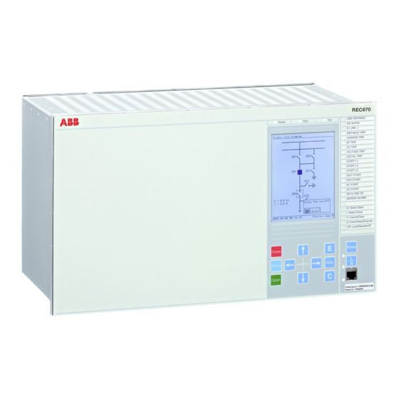
Section 4 1MRK511228-UUS D Understand the IED local human-machine interface Section 4 Understand the IED local human-machine interface About this chapter This chapter describes the display, its keys (buttons) and LEDs that make up the local HMI on the IED. How the keys are used to navigate the HMI, how to interpret the graphic information on the LCD and, what the LEDs indicate is explained in the sections that follow. - Page 28 Section 4 1MRK511228-UUS D Understand the IED local human-machine interface IEC06000531 V1 EN Figure 4: The HMI keypad. Table describes the HMI keys that are used to operate the IED. Table 1: HMI keys on the front of the IED Function Press to close or energize a breaker or disconnector.
-
Page 29: Key Activated Screens
Section 4 1MRK511228-UUS D Understand the IED local human-machine interface Function Press to navigate forward between screens and move right in editing mode. IEC05000109 V1 EN Press to navigate backwards between screens and move left in editing mode. IEC05000110 V1 EN Press to move up in the single line diagram and in the menu tree. -
Page 30: Lcd
Section 4 1MRK511228-UUS D Understand the IED local human-machine interface 4.4.1 Medium The following case sizes can be equipped with the medium size LCD: • 1/2 x 19” • 3/4 x 19” • 1/1 x 19” This is a fully graphical monochrome LCD which measures 4.7 x 3.5 inches. It has 28 lines with up to 40 characters per line. -
Page 31: Indication Leds
Section 4 1MRK511228-UUS D Understand the IED local human-machine interface 4.5.3 Indication LEDs The LED indication module comprising 15 LEDs is standard in 670 series. Its main purpose is to present an immediate visual information for protection indications or alarm signals. Alarm indication LEDs and hardware associated LEDs are located on the right hand side of the front panel. -
Page 32: How To Navigate
Section 4 1MRK511228-UUS D Understand the IED local human-machine interface How to navigate 4.7.1 Read To read values and access information about the objects being monitored the operator must navigate the menu tree using the arrow keys. The active submenu or value is highlighted. - Page 33 Section 4 1MRK511228-UUS D Understand the IED local human-machine interface By pressing the L/R key until the uppermost of the two LEDs next to the key lights up, local operator control can be exercised from the HMI. An apparatus is selected using the up and down arrow keys. The active apparatus is highlighted in the display.
-
Page 35: Section 5 Understand The Hmi Tree
Section 5 1MRK511228-UUS D Understand the HMI tree Section 5 Understand the HMI tree About this chapter This chapter describes the structure of the HMI. The main menu includes submenus such as Measurements, Events, Disturbance Report, Settings, Diagnostics, Test and Reset. - Page 36 Section 5 1MRK511228-UUS D Understand the HMI tree Main menu Sub menu Sub-sub menu General settings Power system Communication Analog modules I/O modules Current protection Voltage protection Control Monitoring Metering Setting group N Differential protection Current protection Voltage protection Frequency protection Multipurpose protection Scheme communication Secondary system supervision...
-
Page 37: Section 6 Read Measured Values
Section 6 1MRK511228-UUS D Read measured values Section 6 Read measured values About this chapter This chapter describes measurement categories and how to locate them using the HMI. Each measurement category has a section of its own that includes a general description of the type of quantity being measured and the path in the local HMI to the measurement. -
Page 38: View Analog Primary Values
Section 6 1MRK511228-UUS D Read measured values the measurements menu the operator will only see data from the hardware and software installed. View analog primary values 6.2.1 Overview The analog primary values are analog quantities measured on the primary side of the TRM and reflect the actual current or voltage on the primary side of the VTs and CTs. -
Page 39: View Analog Mean Values
Section 6 1MRK511228-UUS D Read measured values Displays up to 24 channels with secondary CT and VT data. RMS values are shown. View analog mean values 6.4.1 Overview Measurements from the Milliampere Input Module (MIM) are found in this part of the measurements menu. -
Page 40: Current Phasors Cmmxu
Section 6 1MRK511228-UUS D Read measured values 6.5.2 Current phasors CMMXU Main menu/Measurement/Monitoring/CurrentPhasors(MMXU)/CMMXU:x All three phase currents and their phase angles are displayed here. 6.5.3 Voltage phasors VMMXU/VNMMXU Main menu/Measurements/Monitoring/VoltagePhasors(MMXU)/Phase - Phase/ VMMXU:x Phase to phase voltages and phase angles are displayed here. Main menu/Measurement/Monitoring/VoltagePhasors(MMXU)/Phase - Earth/ VNMMXU:x Phase to ground voltages and phase angles are displayed here. -
Page 41: View Metering Values
Section 6 1MRK511228-UUS D Read measured values View metering values 6.6.1 Pulse counter logic PCGGIO Main menu/Measurements/Metering/PulseCounter(PCGGIO)/PCGGIO:x The output data generated from the pulse counter function include data about the status of the counter and counter values. 6.6.2 Function for energy calculation and demand handling ETPMMTR Main menu/Measurements/Metering/ThreePhEnergMeas(MMTR)/ETPMMTR:x The output data generated from the energy measuring function includes active forward/... -
Page 43: Section 7 Event List
Section 7 1MRK511228-UUS D Event list Section 7 Event list About this chapter This chapter describes how to find and read the event list. View events 7.1.1 Overview Events displays recorded events such as trips and breaker opened or closed. Main menu/Events Displays a list of events in chronological order and where each event has a time stamp. -
Page 45: Section 8 Handle Disturbances
Section 8 1MRK511228-UUS D Handle disturbances Section 8 Handle disturbances About this chapter This chapter describes disturbance detection and handling. This includes resetting LED alarms, triggering disturbance reports, fault distance calculation and the viewing of several fault indicators. Identify a disturbance A disturbance record can be generated manually by using the Manual Trig functionality in the HMI menu. -
Page 46: View Event Recordings
Section 8 1MRK511228-UUS D Handle disturbances 8.2.3 View event recordings The Event recording section in the Disturbance report shows the recording number. The path in the HMI is shown below. Main menu/Disturbance records/Record xx/Event recording 8.2.4 View trip values In the Trip values section of a disturbance recording both the pre-fault and the fault values for current, voltage and phase angle can be viewed. -
Page 47: Section 9 Read And Change Settings
Section 9 1MRK511228-UUS D Read and change settings Section 9 Read and change settings About this chapter This chapter describes how to find and change settings and parameters. The chapter is divided into two sections which match the way the two categories of settings are divided up in the HMI. -
Page 48: Timesynch
Section 9 1MRK511228-UUS D Read and change settings 9.1.2.2 TimeSynch Main menu/Settings/Time/Synchronization/TIMESYNCHGEN:x/General Here the parameters FineSyncSource, CourseSyncSrc and SyncMaster are switched on or off. Main menu/Settings/Time/Synchronization/TIMESYNCHGEN:x/IEC61850-9-2 The synchronization parameters for IEC 61850-9-2LE process bus communication are set here. 9.1.2.3 TIMESYNCHBIN Main menu/Settings/Time/Synchronization/SYNCHBIN:x Binary input synchronization settings available here are the position of the of the module, the number of the binary input and the detection mode. -
Page 49: General Settings
Section 9 1MRK511228-UUS D Read and change settings The time zone according to Coordinated Universal Time (UTC) is set here. General settings Parameters under General settings that are changed will cause the IED to restart. This occurs automatically and requires no manual intervention. The IED must be in setting group 1 before changing settings in General settings 9.2.1... -
Page 50: Remote Communication
Section 9 1MRK511228-UUS D Read and change settings 9.2.2.2 Remote communication Main menu/Settings/General settings/Communication/LDCM configuration/ LDCMX Displays settings for Remote Binary Communication (CRB) and for Remote Multi Communication (CRM). The multi communication block can send both binary and analog data whereas the binary can only send binary data. Each instance of CRB has several settable parameters where the channel mode can be set on or off, terminal numbers can be entered, synchronization can be set to master or slave and opto power can be set high or low. -
Page 51: Station Communication
Section 9 1MRK511228-UUS D Read and change settings Main menu/Settings/General settings/Communication/SLM configuration/Rear optical LON port/SPA Settings for SPA over LON are made here. The operation setting is used to switch the function on or off and the slave address setting is where the slave address is entered. Main menu/Settings/General settings/Communication/SLM configuration/Rear optical LON port/Horizontal communication This setting is used to activate or deactivate horizontal communication. -
Page 52: Ethernet Configuration
Section 9 1MRK511228-UUS D Read and change settings Includes available instances of GOOSE binary receive (GOOSEBINRCV) where setting Operation can be set Enabled or Disabled. IEC61850–8–1 Main menu/Settings/General settings/Communication/Station communication/ IEC61850–8–1 Includes settings for the IED name, Operation (Enabled/Disabled) and GOOSE. Multicommand send Main menu/Settings/General settings/Communication/Station communication/ MultiCommandSend/MULTICMDSND:x... -
Page 53: Analog And I/O Modules
Section 9 1MRK511228-UUS D Read and change settings Main menu/Settings/General settings/Communication/Ethernet configuration/ Rear OEM-Port AB The IP address, IP mask and Mode for the IEC 61850-8-1 communication using the Optical Ethernet Module (OEM) at the rear of the IED are set here. Main menu/Settings/General settings/Communication/Ethernet configuration/ Rear OEM-Port CD The IP address (with different IP address when a second channel is used), IP mask and... -
Page 54: I/O Modules
Section 9 1MRK511228-UUS D Read and change settings parameters where the type of channel is set, the primary and secondary values from VTs and CTs and for Current Transformers the WYE point location (line side or busbar side) is set. Main menu/Settings/General Settings/Analog modules/MergingUnit Displays parameters for the merging units. -
Page 55: Hmi
Section 9 1MRK511228-UUS D Read and change settings 9.2.4 9.2.4.1 Overview Under HMI in General settings there are submenus for LEDs, Screen, Functions, Reference channel service values and the Change lock function. In the LED submenu there are settings for operation, illumination times, and sequence types for the LEDs on the IED front panel. -
Page 56: Control
Section 9 1MRK511228-UUS D Read and change settings 9.2.5 Control 9.2.5.1 Apparatus control Overview Under Control in General settings, parameters for Apparatus control can be adjusted. These are the parameters for among others Bay control, Switch controller, Reservation input, Circuit breakers and Circuit switches. The parameters include delay times, dependencies, pulse times and characteristics. -
Page 57: Control Commands
Section 9 1MRK511228-UUS D Read and change settings Local/Remote switch LocalRemote, LocRemControl Main menu/Settings/General settings/Control/ApparatusControl/LocalRemote/ LOCREM:x Displays available instances of the local/remote function LocalRemote, LocRemControl that permit the user to set the control mode. Reservation input RESIN Main menu/Settings/General Settings/Control/Apparatus Control/ ReservationInput/RESINX:y Displays available instances of the Reservation input function RESIN with one settable parameter per function for future use. -
Page 58: Synchronism-Check And Energizing Check Sesrsyn (25)
Section 9 1MRK511228-UUS D Read and change settings A number of selector switches SLGGIO can be configured in the system. These are substitutes for rotating physical switches. The parameter setting StopAt Extremesis used to disable or enable the end position of the switch. Versatile switch VSGGIO Main menu/Settings/General settings/Control/Commands/VersatileSwitch/ VSGGIO:x... -
Page 59: Monitoring
Section 9 1MRK511228-UUS D Read and change settings Displays available instances of the synchronism-check function SESRSYN (25) with several settings per instance. There are settings for operation, voltage differences and limits, time delays etc. 9.2.6 Monitoring 9.2.6.1 Overview Under monitoring there are parameters for setting Service values, current phasors, Voltage phasors, Disturbance reports, Fault locator and the Measured value expander block. -
Page 60: Current Sequence Components Cmsqi
Section 9 1MRK511228-UUS D Read and change settings 9.2.6.5 Current sequence components CMSQI Main menu/Settings/General settings/Monitoring/Current sequence components(MSQI)/CMSQI:x The current sequence components are where the user sets the limits and deadband settings for current sequence components. The designation for zero sequence current is 3I0, for positive sequence current it is I1 and for negative sequence current it is I2. -
Page 61: Fault Locator Lmbrflo
Section 9 1MRK511228-UUS D Read and change settings There are some groups of a number of channels with a number of analog signals per channel. Each signal has some settable parameters such as operation, Nominal value and trig values. 9.2.6.8 Fault locator LMBRFLO Main menu/Settings/General Settings/Monitoring/FaultLocator(RFLO)/ LMBRFLO:1... -
Page 62: Metering
Section 9 1MRK511228-UUS D Read and change settings with user defined settings. The standard settings include some standard service value thresholds. In the Disturbance report menu Binary signal parameters on up to 96 channels are configured. 9.2.7 Metering 9.2.7.1 Overview Under metering there are settings for the Pulse counter function. -
Page 63: Differential Protection
Section 9 1MRK511228-UUS D Read and change settings 9.3.2 Differential protection 9.3.2.1 Overview The settings available for differential protection in Setting group N are not the same as those under General settings. The main difference is that settings in the Setting group N category can be changed on the fly without the IED requiring a restart. -
Page 64: Broken Conductor Check Brcptoc (46)
Section 9 1MRK511228-UUS D Read and change settings 9.3.3.3 Broken conductor check BRCPTOC (46) Main menu/Settings/Setting Group N/Current protection/ BrokenCondCheck(PTOC,46)/BRCPTOC:x Includes current and timer settings. 9.3.3.4 Capacitor bank protection CBPGAPC Main menu/Settings/Setting Group N/Current protection/ CapacitorBankProtection(GAPC)/CBPGAPC:x Displays some instances of CBPGAPC. 9.3.3.5 Directional over-power protection GOPPDOP (32) Main menu/Settings/Setting Group N/Current protection/... -
Page 65: Four Step Directional Negative Phase Sequence Overcurrent Protection Ns4Ptoc (46I2)
Section 9 1MRK511228-UUS D Read and change settings threshold current as a percentage of IBase, and the multiplier for the current threshold level. 9.3.3.9 Four step directional negative phase sequence overcurrent protection NS4PTOC (46I2) Main menu/Settings/Setting group N/Current protection/ NegSecOverCurr4Step(PTOC,46I2)/NS4PTOC:x Displays instances of NS4PTOC (46I2). -
Page 66: Stub Protection Stbptoc (50Stb)
Section 9 1MRK511228-UUS D Read and change settings 9.3.3.14 Stub protection STBPTOC (50STB) Main menu/Settings/Setting Group N/Current protection/Stub(PTOC,50STB)/ STBTOC:x Displays instances of STBPTOC (50STB) with some settings per instance. These are operation, base current settings, release mode, operate current pickup and time delay. 9.3.3.15 Thermal overload protection, one time constant LPTTR (26) Main menu/Settings/Setting Group N/Current protection/... -
Page 67: Two Step Overvoltage Protection Ov2Ptov (59)
Section 9 1MRK511228-UUS D Read and change settings 9.3.4.3 Two step overvoltage protection OV2PTOV (59) Main menu/Settings/Setting Group N/Voltage protection/ OverVoltage2Step(PTOV,59)/OV2PTOV:x Displays several settable parameters including settings for Time Overvoltage Curves (TOC) and other function related settings. 9.3.4.4 Two step residual overvoltage protection ROV2PTOV (59N) Main menu/Settings/Setting Group N/Voltage protection/ ResidualOverVoltage2Step(PTOV,59N)/ROV2PTOV:x Displays up to several settable parameters for characteristics and many related... -
Page 68: Rate-Of-Change Frequency Protection Sapfrc (81)
Section 9 1MRK511228-UUS D Read and change settings Displays available instances of SAPTOF (81) with a number of settings per instance. The settings are operation, pickup frequency, base voltage setting, internal blocking level, operate time delay and reset time delay. For the Overfrequency function to operate correctly the Operation setting must be Enabled. -
Page 69: Scheme Communication
Section 9 1MRK511228-UUS D Read and change settings 9.3.7 Scheme communication 9.3.7.1 Overview Under Scheme communication there are settings for Zone scheme communication, Zone current reversal, Local acceleration logic, EF Scheme communication and EF Current reversal weak end infeed. In each category the function can be switched On or Off and time delays, ratings and parameters can be set. -
Page 70: Local Acceleration Logic Zclcplal
Section 9 1MRK511228-UUS D Read and change settings 9.3.7.6 Local acceleration logic ZCLCPLAL Main menu/Settings/Setting group N/Scheme communication/Local AccelerationLogic(PLAL)/ZCLCPLAL:x Displays available settable parameters for setting OperationOn or Off, setting time delays, enable and disable various functions. 9.3.8 Secondary system supervision 9.3.8.1 Overview Under Secondary circuit supervision there are settings for Current circuit supervision... -
Page 71: Autorecloser Smbrrec (79)
Section 9 1MRK511228-UUS D Read and change settings circuit breakers. The autorecloser settings include the number of shots, first shot combinations and many other useful settings. 9.3.9.2 Autorecloser SMBRREC (79) Main menu/Settings/Setting Group N/Control/AutoRecloser(RREC,79)/ SMBRREC:x Displays available instances of the autorecloser function SMBRREC (79) with several settable parameters per instance. -
Page 72: Automatic Voltage Control For Tapchanger, Parallel Control Tr8Atcc (90)
Section 9 1MRK511228-UUS D Read and change settings 9.3.9.7 Automatic voltage control for tapchanger, parallel control TR8ATCC (90) Main menu/Settings/Setting Group N/Control/ TransformerVoltageControl(ATCC,90)/TR8ATCC:x Parameters for current and voltage levels, deadbands, timers and alarm levels are found here. 9.3.10 Monitoring 9.3.10.1 Overview Event counter and fault locator settings are found under Monitoring in the Setting Group N menu. -
Page 73: Tripping Logic Smpptrc (94)
Section 9 1MRK511228-UUS D Read and change settings 9.3.11.2 Tripping logic SMPPTRC (94) Main menu/Settings/Setting group N/Logic/TripLogic(PTRC,94)/SMPPTRC:x Displays available instances of the trip logic function SMPPTRC (94) with some settable parameters per instance. The settable parameters include operation, tripping order, trip lockout and minimum duration of trip output signal. 9.3.11.3 Trip matrix logic TMAGGIO Main menu/Settings/Setting group N/Logic/TripMatrix(GGIO)/TMAGGIO:x... -
Page 74: Logictimerset
Section 9 1MRK511228-UUS D Read and change settings 9.3.11.9 LogicTimerSet Main menu/Settings/Setting Group N/Logic/LogicTimerSet/TIMERSET:x Displays settable parameters for Operation (Enabled or Disabled) and delay for settable timer. 9.3.11.10 LogicTimerSet_qt Main menu/Settings/Setting Group N/Logic/LogicTimerSet_qt/TIMERSETQT:x Displays settable parameters for operation (On or Off) and delay for settable timer. Activate setting group Main menu/Settings/Activate setting group Available setting groups can be configured in PCM600. -
Page 75: Section 10 Diagnose Ied Status
Section 10 1MRK511228-UUS D Diagnose IED status Section 10 Diagnose IED status About this chapter This chapter describes where in the HMI tree to find the cause of an internal IED failure and information about the IED as such. 10.1 Read internal events Main menu/Diagnostics/Internal events Internal events in the diagnostics menu of the HMI tree shows a time stamped list of... - Page 76 Section 10 1MRK511228-UUS D Diagnose IED status Main menu/Diagnostics/IED status/Merging units/MergingUnit:x The list includes all the status signals of each merging unit. Main menu/ Diagnostics/Communication/Front port Displays various communication status signals for front port communication. Main menu/ Diagnostics/Communication/Rear OEM - port AB Displays various communication status signals for rear AB port communication.
-
Page 77: Section 11 Test The Ied
Section 11 1MRK511228-UUS D Test the IED Section 11 Test the IED About this chapter This chapter describes the tests that can be performed in the test section of the HMI. 11.1 Overview The test part of the tree view in the HMI has a number of submenus for test and viewing activities. -
Page 78: Ied Test Mode
Section 11 1MRK511228-UUS D Test the IED measurements and number and kind of reclosing attempts. Apparatus control includes up to 19 functions each with their own set of measurement data regarding interlocking, breaker and isolator conditions. Scheme communication includes functions that display trip and other signals used when interzone communication is deployed. -
Page 79: Binary Input Module Bim
Section 11 1MRK511228-UUS D Test the IED 11.3.1.1 Binary Input Module BIM Main menu/Test/Binary input values/Binary input modules Displays available binary input modules with several binary values per module. 11.3.1.2 Signal matrix for binary input SMBI Main menu/Test/Binary Input Values/SMT binary inputs/Instance:x Displays available instances of SMT binary inputs with several inputs per instance. -
Page 80: Differential Protection
Section 11 1MRK511228-UUS D Test the IED 11.5.2 Differential protection Main menu/Test/Function test modes/Differential protection Test of the high impedance restricted ground fault protection. 11.5.3 Current protection Main menu/Test/Function test modes/Current protection Test of breaker failure protection, phase overcurrent protection,residual overcurrent protection instantaneous phase overcurrent protection,pole discrepancy protection,instantaneous residual overcurrent protection, thermal overload protection, and stub protection. -
Page 81: Control
Section 11 1MRK511228-UUS D Test the IED Test of current circuit supervision and fuse failure supervision. 11.5.9 Control Main menu/Test/Function test modes/Control Test of synchronism-check and energizing check function as well as auto-reclosing function. 11.5.10 Monitoring Main menu/Test/Function test modes/Monitoring Test of monitoring functions such as event counter and disturbance report. -
Page 82: Current Protection
Section 11 1MRK511228-UUS D Test the IED 11.6.3 Current protection Viewable data under Current protection consists mainly of trip status data under the various categories of current protection which include overcurrent protection, thermal overload, stub protection, pole discrepancy and variations of these. 11.6.3.1 Breaker failure protection CCRBRF (50BF) Main menu/Test/Function status/Current protection/BreakerFailure(RBRF,... -
Page 83: Instantaneous Phase Overcurrent Protection Phpioc (50)
Section 11 1MRK511228-UUS D Test the IED 11.6.3.6 Instantaneous phase overcurrent protection PHPIOC (50) Main menu/Test/Function status/Current protection/ InstPhaseOverCurrent(PIOC,50)/PHPIOC:x Displays available instances of PHPIOC (50) with a number of measurements per instance showing the trip status in general and per phase. 11.6.3.7 Instantaneous residual overcurrent protection EFPIOC (50N) Main menu/Test/Function status/Current protection/... -
Page 84: Sensitive Directional Residual Over Current And Power Protection Sdepsde (67N)
Section 11 1MRK511228-UUS D Test the IED Displays available instances of EF4PTOC (51N,67N) with a number of measurements per instance. The measurements indicate trip and pickup signal status as well as the 2nd harmonic block signal status. 11.6.3.12 Sensitive directional residual over current and power protection SDEPSDE (67N) Main menu/Test/Function status/Current protection/SensDirResOvCurr(PSDE, 67N)/SDEPSDE:x... -
Page 85: Loss Of Voltage Check Lovptuv (27)
Section 11 1MRK511228-UUS D Test the IED 11.6.4.1 Loss of voltage check LOVPTUV (27) Main menu/Test/Function status/Voltage protection/LossofVoltage(PTUV,27)/ LOVPTUV:x Displays the output data of LOVPTUV (27). 11.6.4.2 Two step overvoltage protection OV2PTOV (59) Main menu/Test/Function status/Voltage protection/OverVoltage2Step(PTOV,59)/ OV2PTOV:x Displays available instances of OV2PTOV (59) with several measurements per instance. -
Page 86: Overfrequency Protection Saptof (81)
Section 11 1MRK511228-UUS D Test the IED 11.6.5.1 Overfrequency protection SAPTOF (81) Main menu/Test/Function status/Frequency protection/OverFrequency(PTOF)/ SAPTOF:x Displays available instances of SAPTOF (81) with some measurements per instance consisting of trip and pickup signal status. The pickup duration as percentage of the total trip time and a blocking indication as a result of low voltage. -
Page 87: Scheme Communication
Section 11 1MRK511228-UUS D Test the IED 11.6.7 Scheme communication Scheme communication functions which are used in conjunction with distance protection generate viewable data about the signals used in these applications. Depending on the options chosen, data about weak end infeed, ground faults etc. is sent to and from IEDs. -
Page 88: Secondary System Supervision
Section 11 1MRK511228-UUS D Test the IED Displays available measurements indicating trip by loss of load or by zone extension 11.6.8 Secondary system supervision Values for Current circuit supervision and Fuse failure supervision are found under Secondary circuit supervision. Fail and alarm detection information is available together with various pickup and current data. - Page 89 Section 11 1MRK511228-UUS D Test the IED intermediate or in a bad state as defined in IEC61850. The enable close (EN_CLOSE) parameter is subject to similar conditions. Interlock busbarground switch BB_ES Main menu/Test/Function status/Control/Apparatus control/ InterlBusbarEarthSwitch/BB_ES:x The information shown here indicates whether or not switching of the ground switch is permitted and also indicates whether the ground switch 89Gis in the open or closed position.
- Page 90 Section 11 1MRK511228-UUS D Test the IED Displays available measurements per breaker arrangement (instances of BH_LINE_AIL). The measurements show the states of the various disconnectors, breakers and grounding switches. Interlock one and a half circuit breaker-and-a-half line B BH_LINE_B Main menu/Test/Function status/Control/Apparatus control/Interl11½CBLineB/ BH_LINE_B:x Displays available measurements per arrangement (instance of BH_LINE_B) showing conditions for breakers, disconnectors and grounding switches in the arrangement.
- Page 91 Section 11 1MRK511228-UUS D Test the IED allowed and also indicate the status and validity of devices. For example, the measurement named 1289OPTR indicates whether or not 189 and 289 are in the open position. If the output for this measurement is 1 then 189 and 289 are in the open position.
-
Page 92: Autorecloser Smbrrec (79)
Section 11 1MRK511228-UUS D Test the IED outputs, the measurement outputs have boolean values indicating the status of processes and devices. Bay reserve QCRSV Main menu/Test/Function status/Control/Apparatus control/BayReserve(CRSV)/ QCRSV:x Displays available instances of the function QCRSV with several measurements per instance. -
Page 93: Commands
Section 11 1MRK511228-UUS D Test the IED 11.6.9.3 Commands In the commands menu it is possible to view three sets of values. These are found under the submenus menucascade/uicontrol. Automation bits, command function for DNP3.0 AutomationBits Main menu/Test/Function status/Control/Commands/Automation Bits/ AUTOBITS:x Displays the output data of the AutomationBits function. -
Page 94: Iec61850 Generic Communication I/O Functions Dpggio
Section 11 1MRK511228-UUS D Test the IED 11.6.9.4 IEC61850 generic communication I/O functions DPGGIO Main menu/Test/Function status/Control/DoubelPointIndication(DPGGIO)/ DPGGIO:x Displays the output data of the DPGGIO function. 11.6.9.5 Synchronism check and energizing check SESRSYN (25) Main menu/Test/Function status/Control/Synchronizing(RSYN,25)/SESRSYN:x Displays available instances of SESRSYN (25) with a number of measurements per instance. -
Page 95: Logical Signal Status Report Binstatrep
Section 11 1MRK511228-UUS D Test the IED 11.6.10.1 Logical signal status report BINSTATREP Main menu/Test/Function status/Monitoring/BinarySignalStatusReport/ BINSTATREP:x Displays sets of output measurements with several outputs per set of measurements. 11.6.10.2 Disturbance report DRPRDRE Test/Function status/Monitoring/DisturbanceReport(RDRE) Displays data about disturbance reports. The disturbance report can be switched off, a disturbance report that has been initiated is indicated by a boolean number, as are completed reports and cleared reports. -
Page 96: Global Positioning System
Section 11 1MRK511228-UUS D Test the IED 11.6.10.6 Global positioning system Main menu/Test/Function status/Monitoring/GPS Displays the number of satellites supplying positioning and timing data to the GPS module. 11.6.10.7 IEC61850 generic communication I/O functions 16 inputs SP16GGIO Main menu/Test/Function status/Monitoring/IndicationBits(GGIO)/SP16GGIO:x Displays the output data of the SP16GGIO function. -
Page 97: Boolean 16 To Integer Conversion B16Ifcvi, B16I
Section 11 1MRK511228-UUS D Test the IED 11.6.11.1 Boolean 16 to Integer conversion B16IFCVI, B16I Main menu/Test/Function status/Logic/Bool16ToInt(FCVI)/B16IFCVI:x Main menu/Test/Function status/Logic/Bool16ToInt/B16I:x Displays the output data of the Bool16ToInt function. 11.6.11.2 Integer to Boolean 16 conversion IB16FCVB, IB16 Main menu/Test/Function status/Logic/IntToBool16(FCVB)/IB16FCVB:x Main menu/Test/Function status/Logic/IntToBool16/IB16:x Displays the output data of the IntToBool16 function. -
Page 98: Logic Sr/Rs Memory Qt
Section 11 1MRK511228-UUS D Test the IED Displays available instances of the function SRMEMORY/RSMEMORY. The output data presented in the HMI is boolean and indicates whether or not a signal is present. For example, an output of one from RSMEMORY1 OUT indicates that a signal exists on that output. -
Page 99: Station Communication
Section 11 1MRK511228-UUS D Test the IED Displays an application dependent number of instances of CRB (Remote Binary Communication) and CRM (Remote Multi Communication) with measurement data. 11.6.12.2 Station communication GOOSE binary receive Main menu/Test/Function status/Communication/Station communication/ GOOSEBinReceive/GOOSEBINRCV:x Available GOOSE binary signals can be viewed here. There are a number of signal indications per set. -
Page 100: Test
Section 11 1MRK511228-UUS D Test the IED 11.6.14 Test Main menu/Test/Function status/Test Displays the parameters ACTIVE, OUTPUT and SETTING. The ACTIVE parameter indicates whether the IED is in test mode or not, the OUPUT parameter indicates whether test mode has been activated by a binary input and the SETTING parameter indicates whether or not test mode has been activated by a setting. -
Page 101: Section 12 Control And Supervise The Bay
Section 12 1MRK511228-UUS D Control and supervise the bay Section 12 Control and supervise the bay About this chapter This chapter describes the various control and supervision functions available in the HMI. In particular, how the single line diagram available on the display can be used for this purpose. -
Page 102: Locating And Using The Single Line Diagram
Section 12 1MRK511228-UUS D Control and supervise the bay 12.1.2 Locating and using the single line diagram It is possible to navigate the SLD screen using the up and down keys on the IED keypad. The apparatus under control is highlighted as the user moves from symbol to symbol using the keypad. -
Page 103: Control Screen Messages
Section 12 1MRK511228-UUS D Control and supervise the bay Symbol Description Disconnector xx05000238.vsd IEC05000238 V1 EN Junction xx05000240.vsd IEC05000240 V1 EN Motor xx05000241_ansi.vsd ANSI05000241 V1 EN Reactor xx05000242_ansi.vsd ANSI05000242 V1 EN Surge arrestor xx05000243_ansi.vsd ANSI05000243 V1 EN Trafo 2 windings xx05000244_ansi.vsd ANSI05000244 V1 EN Trafo 3 windings... -
Page 105: Section 13 Reset
Section 13 1MRK511228-UUS D Reset Section 13 Reset About this chapter This chapter describes how to reset the IED and when this is necessary. 13.1 Reset guide for IED 13.1.1 Reset counters 13.1.1.1 Reset autorecloser SMBRREC (79) The recorded number of reclosings are reset under Reset counters in the HMI tree. Main menu/Reset/Reset counters/Autorecloser(RREC,79)/SMBRREC:x In the dialog box that appears, choose YES to reset. -
Page 106: Reset Pulse Counter Pcggio
Section 13 1MRK511228-UUS D Reset 13.1.1.5 Reset pulse counter PCGGIO The Pulse counter is reset under Reset counters menu in the HMI tree. Main menu/Reset/Reset counters/PulseCounter(GGIO)/PCGGIO:x In the dialog box that appears, choose YES to reset. 13.1.1.6 LDCM clear counters Main menu/Reset/Reset counters/LDCMCommunication/LDCMX Activating Reset of LDCM counters sets the counter concerned to zero. -
Page 107: Reset Leds
Section 13 1MRK511228-UUS D Reset 13.1.3 Reset LEDs 13.1.3.1 Start and trip LEDs By activating this reset, the colored LEDs above the LCD, if they are latched, will be reset. Main menu/Reset/Reset LEDs/Start and trip LEDs In the dialog box that appears, choose YES to reset. 13.1.3.2 All indication LEDs Activating the Reset of indication LEDs will zero all fifteen LEDs to the right of the LCD. - Page 108 Section 13 1MRK511228-UUS D Reset Main menu/Reset/Reset temperature/ThermalOverload2TimeConstant(PTTR,49)/ TRPTTR:x In the dialog box that appears, choose YES to reset. Operator's manual...
-
Page 109: Section 14 Authorization
Section 14 1MRK511228-UUS D Authorization Section 14 Authorization About this chapter This chapter describes password procedures and levels of access in the system. 14.1 Overview To safeguard the interests of our customers, both the IED and the tools that are accessing the IED are protected, by means of authorization handling. - Page 110 Section 14 1MRK511228-UUS D Authorization Table 2: Pre-defined user types Access rights System Protection Design User Guest Super User SPA Guest Operator Engineer Engineer Administrator Basic setting possibilities (change setting group, control settings, limit supervision) Advanced setting possibilities (for example protection settings) Basic control possibilities (process control, no bypass) Advanced control possibilities (process...
-
Page 111: Logon Or Logoff
Section 14 1MRK511228-UUS D Authorization At least one user must be included in the UserAdministrator group to be able to write users, created in PCM600, to IED. 14.3 LogOn or logOff The Authorization menu allows the user to logOn and, logOff. The HMI path is as follows: Main menu/Authorization 14.4 Authorization handling in the IED... -
Page 112: Internet Protocol Ports Security Guideline
Section 14 1MRK511228-UUS D Authorization on has failed, then the Log on window opens again, until either the user makes it right or presses “Cancel”. 14.5 Internet Protocol ports security guideline The Internet Protocol ports security guide line can not suggest concrete products for a secure system setup. - Page 113 Section 14 1MRK511228-UUS D Authorization • The Internet Protocol port used for file transfer (default port 21) is fixed and cannot be changed. • The Internet Protocol port used for IEC61850 (default port 102) is fixed and can not be changed. •...
-
Page 115: Section 15 Glossary
Section 15 1MRK511228-UUS D Glossary Section 15 Glossary About this chapter This chapter contains a glossary with terms, acronyms and abbreviations used in ABB technical documentation. Alternating current Application configuration tool within PCM600 A/D converter Analog-to-digital converter ADBS Amplitude deadband supervision... - Page 116 Section 15 1MRK511228-UUS D Glossary Controller Area Network. ISO standard (ISO 11898) for serial communication Circuit breaker Combined backplane module CCITT Consultative Committee for International Telegraph and Telephony. A United Nations-sponsored standards body within the International Telecommunications Union. CAN carrier module CCVT Capacitive Coupled Voltage Transformer Class C...
- Page 117 Section 15 1MRK511228-UUS D Glossary Data flow control Discrete Fourier transform DHCP Dynamic Host Configuration Protocol DIP-switch Small switch mounted on a printed circuit board Digital input DLLB Dead line live bus Distributed Network Protocol as per IEEE Std 1815-2012 Disturbance recorder DRAM Dynamic random access memory...
- Page 118 Section 15 1MRK511228-UUS D Glossary Gas-insulated switchgear GOOSE Generic object-oriented substation event Global positioning system GSAL Generic security application GPS Time Module HDLC protocol High-level data link control, protocol based on the HDLC standard HFBR connector type Plastic fiber connector Human-machine interface HSAR High speed autoreclosing...
- Page 119 Section 15 1MRK511228-UUS D Glossary One instance of a function is identical to another of the same kind but has a different number in the IED user interfaces. The word "instance" is sometimes defined as an item of information that is representative of a type. In the same way an instance of a function in the IED is representative of a type of function.
- Page 120 Section 15 1MRK511228-UUS D Glossary Multifunction vehicle bus. Standardized serial bus originally developed for use in trains. National Control Centre Numerical module OCO cycle Open-close-open cycle Overcurrent protection Optical ethernet module OLTC On-load tap changer Over-voltage Overreach A term used to describe how the relay behaves during a fault condition.
- Page 121 Section 15 1MRK511228-UUS D Glossary RS422 A balanced serial interface for the transmission of digital data in point-to-point connections RS485 Serial link according to EIA standard RS485 Real-time clock Remote terminal unit Substation Automation Select-before-operate Switch or push button to close Station control system SCADA Supervision, control and data acquisition...
- Page 122 Section 15 1MRK511228-UUS D Glossary TCP/IP Transmission control protocol over Internet Protocol. The de facto standard Ethernet protocols incorporated into 4.2BSD Unix. TCP/IP was developed by DARPA for Internet working and encompasses both network layer and transport layer protocols. While TCP and IP specify two protocols at specific protocol layers, TCP/IP is often used to refer to the entire US Department of Defense protocol suite based upon these, including Telnet, FTP, UDP and RDP.
- Page 123 Section 15 1MRK511228-UUS D Glossary Three times zero-sequence current. Often referred to as the residual or the -fault current Three times the zero sequence voltage. Often referred to as the residual voltage or the neutral point voltage Operator's manual...
- Page 126 ABB Inc. 3450 Harvester Road Burlington, ON L7N 3W5, Canada Phone Toll Free: 1-800-HELP-365, menu option #8 ABB Mexico S.A. de C.V. Paseo de las Americas No. 31 Lomas Verdes 3a secc. 53125, Naucalpan, Estado De Mexico, MEXICO Phone (+1) 440-585-7804, menu...
Need help?
Do you have a question about the REC670 ANSI and is the answer not in the manual?
Questions and answers