Table of Contents
Advertisement
Available languages
Available languages
Quick Links
INSTALLATION AND OPERATION MANUAL
MANUAL DE INSTALACIÓN Y FUNCIONAMIENTO
INSTALLATIONS- UND BETRIEBSHANDBUCH
MANUEL D'INSTALLATION ET DE FONCTIONNEMENT
MANUALE D'INSTALLAZIONE E D'USO
MANUAL DE INSTALAÇÃO E DE FUNCIONAMENTO
INSTALLATIONS- OG BETJENINGSVEJLEDNING
INSTALLATIE- EN BEDIENINGSHANDLEIDING
INSTALLATION- OCH DRIFTHANDBOK
ΕΓΧΕΙΡΙΔΙΟ ΕΓΚΑΤΑΣΤΑΣΗΣ ΚΑΙ ΛΕΙΤΟΥΡΓΙΑΣ
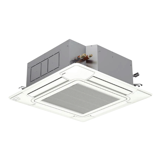
INDOOR UNITS SYSTEM FREE
RCI-(1.0-6.0)FSN4 / P-N23NA2
РЪКОВОДСТВО ЗА ИНСТАЛИРАНЕ И ЕКСПЛОАТАЦИЯ
NÁVOD K MONTÁŽI A OBSLUZE
PAIGALDUS- JA KASUTUSJUHEND
TELEPÍTÉSI ÉS ÜZEMELTETÉSI ÚTMUTATÓ
UZSTĀDĪŠANAS UN EKSPLUATĀCIJAS ROKASGRĀMATA
MONTAVIMO IR NAUDOJIMO VADOVĄ
INSTRUKCJA MONTAŻU I OBSŁUGI
MANUAL DE INSTALARE SI OPERARE
ИНСТРУКЦИЯ ПО МОНТАЖУ И ЭКСПЛУАТАЦИИ
4 - way cassette
Advertisement
Table of Contents

Related Manuals for Hitachi RCI-6.0FSN4


Summary of Contents for Hitachi RCI-6.0FSN4
- Page 1 РЪКОВОДСТВО ЗА ИНСТАЛИРАНЕ И ЕКСПЛОАТАЦИЯ INSTALLATION AND OPERATION MANUAL NÁVOD K MONTÁŽI A OBSLUZE MANUAL DE INSTALACIÓN Y FUNCIONAMIENTO PAIGALDUS- JA KASUTUSJUHEND INSTALLATIONS- UND BETRIEBSHANDBUCH TELEPÍTÉSI ÉS ÜZEMELTETÉSI ÚTMUTATÓ MANUEL D’INSTALLATION ET DE FONCTIONNEMENT MANUALE D’INSTALLAZIONE E D’USO UZSTĀDĪŠANAS UN EKSPLUATĀCIJAS ROKASGRĀMATA MANUAL DE INSTALAÇÃO E DE FUNCIONAMENTO MONTAVIMO IR NAUDOJIMO VADOVĄ...
- Page 3 Specifikationerna i den här handboken kan ändras utan föregående meddelande för att HITACHI ska kunna leverera de senaste innovationerna till kunderna. Vi på HITACHI gör allt vi kan för att se till att alla specifikationer stämmer, men vi har ingen kontroll över tryckfel och kan därför inte hållas ansvariga för den typen av fel.
- Page 4 HITACHI nie ponosi żadnej odpowiedzialności. Română Specificațiile din acest manual pot fi modificate fără notificare prealabilă, pentru ca HITACHI să poată pune la dispoziția clienților noștri ultimele inovații. Deși depunem toate eforturile pentru a ne asigura că toate specificațiile sunt corecte, erorile de tipărire depășesc controlul HITACHI;...
- Page 5 C A U T I O N This product shall not be mixed with general house waste at the end of its life and it shall be retired according to the ap- propriated local or national regulations in a environmentally correct way. Due to the refrigerant, oil and other components contained in Air Conditioner, its dismantling must be done by a professio- nal installer according to the applicable regulations.
- Page 6 В Н И М А Н И Е В края на своя технологичен живот този продукт не бива да се изхвърля заедно с общите битови отпадъци и трябва да се третира съгласно приетите местни или национални подзаконови нормативни актове по правилен от гледна точка на опазване на...
- Page 7 This product contains biocidal substances according to EU Reg. 528/2012 Este producto contiene sustancias biocidas según el Reg. UE 528/2012 Dieses Produkt enthält Biozide nach EU Verordnung 528/2012 Conformément à la Reg UE 528/2012, ce produit contient des substances biocides Questo prodotto contiene sostanze biocidi ai sensi del Reg.
- Page 8 INDEX INDHOLDSFORTEGNELSE 1 GENERAL INFORMATION 1 GENEREL INFORMATION 2 NAME OF PARTS 2 NAVN PÅ DELE 3 INDOOR UNIT INSTALLATION 3 INSTALLATION AF INDENDØRSENHED 4 REFRIGERANT PIPING 4 KØLEMIDDELRØR 5 DRAIN PIPING 5 AFLØBSRØR 6 ELECTRICAL WIRING 6 ELEKTRISK LEDNINGSFØRING 7 REMOTE CONTROLLER OPERATION 7 FJERNBETJENING 8 INSTALLATION OF AIR PANEL: P-N23NA2...
- Page 9 INDEKS SPIS TREŚCI 1 ÜLDTEAVE 1 INFORMACJE OGÓLNE 2 OSADE NIMED 2 CZĘŚCI SKŁADOWE 3 SISESEADME PAIGALDAMINE 3 MONTAŻ JEDNOSTKI WEWNĘTRZNEJ 4 JAHUTUSTORUSTIK 4 RUROCIĄG CZYNNIKA CHŁODNICZEGO 5 ÄRAVOOLUTORUSTIK 5 PRZEWÓD ODPŁYWU SKROPLIN 6 ELEKTRIÜHENDUSED 6 POŁĄCZENIA ELEKTRYCZNE 7 KAUGJUHTIMISPULDI KASUTAMINE 7 OBSŁUGA ZDALNEGO STEROWNIKA 8 ÕHUPANEELI PAIGALDAMINE: P-N23NA2 8 MONTAŻ...
- Page 10 The English version is the original one; other languages are translated from English. Should any discrepancy occur between the English and the translated versions, the English version shall prevail. La versión en inglés es la original, y las versiones en otros idiomas son traducciones de la inglesa. En caso de discrepancias entre la versión inglesa y las versiones traducidas, prevalecerá...
- Page 11 1.1 GENERAL NOTES No part of this publication may be reproduced, copied, filed HITACHI makes every effort to offer correct, up-to-date or transmitted in any shape or form without the permission of documentation. Despite this, printing errors cannot be controlled Johnson Controls-Hitachi Air Conditioning Spain, S.A.U.
-
Page 12: Important Notice
For use in other applications, a fire, deformities, rusting or faults: please contact your HITACHI dealer or service contractor. Places where oil is present (including oil for machinery). The air conditioning system should only be installed by qualified... -
Page 13: Name Of Parts
NAME OF PARTS Motion sensor kit PS-MSK2 (optional) • Places where hot air from a heater, etc. affects directly the motion sensor. Do not install the motion sensor kit PS-MSK2 (optional) in the • Places where weather affects directly the surface of the following places. -
Page 14: Indoor Unit Installation
INDOOR UNIT INSTALLATION 3 INDOOR UNIT INSTALLATION D A N G E R • Check to ensure that the accessories are packed with the indoor • This unit is exclusive non electrical heater type indoor unit. It is unit. prohibited to install a electrical heater in the field. • Do not install the indoor units outdoors. If installed outdoors, an • Do not put any foreign material into the indoor unit and check to electric hazard or electric leakage will occur. ensure that none exist in the indoor unit before the installation and test running. Otherwise a fire or failure, etc., may occur. • Consider the air distribution from each indoor unit to the space of the room, and select a suitable location so that uniform air temperature in the room can be obtained. The unit must C A U T I O N not be installed below 2.3 metres from the floor level, with a recommended installation height between 2.3 and 3 metres from... - Page 15 INDOOR UNIT INSTALLATION 3.1.2 Initial Check 3.1.3 Installation • Install the indoor unit with a proper clearance around it Mounting of Suspension Bolts paying careful attention of installation direction for the piping, wiring and maintenance working space, as shown below. Mount suspension bolts using M10 (W3/8) as size, as shown.
- Page 16 INDOOR UNIT INSTALLATION Adjusting of space between indoor units and Sensing area for the motion sensor kit PS-MSK2 false ceiling opening (optional) only as an accessory for air panel P-N23NA2 Adjust the indoor unit to the correct position while checking with the pattern for installation.
-
Page 17: Refrigerant Piping
REFRIGERANT PIPING 4 REFRIGERANT PIPING 4.1 PIPING CONNECTION 4.1.1 Piping Position 4.1.2 Size of piping connection Piping size (mm) mm (in) Liquid piping Gas piping RCI-(1.0-2.0) Ø 6.35 (1/4) Ø 12.70 (1/2) RCI-(2.5-6.0) Ø 9.52 (3/8) Ø 15.88 (5/8) ... -
Page 18: Drain Pipe Connection
DRAIN PIPING After performing drain piping work and electrical wiring, check to C A U T I O N ensure that water flows smoothly as in the following procedure: • Do not create an upper-slope or rise for the drain piping, since drain ... -
Page 19: Electrical Wiring
ELECTRICAL WIRING 6 ELECTRICAL WIRING 6.1 GENERAL INFORMATION General Check D A N G E R 1 Make sure that the field-selected electrical components • Turn off the main power switch to the indoor unit and the (main power switches, circuit breakers, wires, conduit outdoor unit before electrical wiring work or a periodical check connectors and wire terminals) have been properly selected. - Page 20 ELECTRICAL WIRING 6.3 SETTINGS OF DIP SWITCHES Quantity and position of Dip switches DSW5 and RSW2: Refrigerant cycle number setting Setting is required. Factory setting: DSW5 RSW2 DSW7 DSW4 DSW5 RSW2 1 2 3 4 1 2 3 4 5 6 1 2 3 4 5 6 1 2 3 4 5 6 1 2 3 4 5 6...
-
Page 21: Remote Controller Operation
REMOTE CONTROLLER OPERATION 7 REMOTE CONTROLLER OPERATION HITACHI recommends PC-ARFP(1)E remote control in order For detailed functions should be referred to remote control to obtain the maximum RCI-(1.0-6.0)FSN4 performance. Installation and Operation Manual. 7.1 HIGH SPEED SETTING FUNCTION This function allow to set the air flow volume higher than normal... -
Page 22: Installation
INSTALLATION OF AIR PANEL: P-N23NA2 8.2 INSTALLATION Check the indoor unit height from the false Installing air panel ceiling surface 1 Remove the cover of the corner pocket (4 portions). Remove Check the distance between the indoor unit and the false pulling A part toward the arrow direction. - Page 23 INSTALLATION OF AIR PANEL: P-N23NA2 8.2.1 Attachment of corner pocket cover 6 When tightening the long screws to prevent air leakage and to be no gap between the false ceiling surface and Attach the corner pocket covers after the air panel is mounted the indoor unit, the inner circumference of the air panel completely.
- Page 24 INSTALLATION OF AIR PANEL: P-N23NA2 Attachment of corner pocket cover with motion Run the relay wire to the corner pocket cover with motion sensor sensor PS-MSK2 on the air panel model P-N23NA2 through the top of fixing plate for the indoor units. Set a length of 100mm to 200mm from the indoor unit to the relay connector.
-
Page 25: Maintenance
MAINTENANCE 9 MAINTENANCE When the indication, “FILTER” is shown on the display of the Do not operate the system without the air filter to protect the remote control switch, take out the air filter according to the indoor unit heat exchanger against being clogged. indicated steps for each unit. -
Page 27: Общая Информация
воспроизведена, скопирована, занесена в файл Тем не менее, при публикации возможны ошибки, которые или передана в какой бы то ни было форме без HITACHI не может контролировать, и за которые не несет предварительного разрешения Johnson Controls-Hitachi Air ответственности. Conditioning Spain, S.A.U. - Page 28 ОБЩАЯ ИНФОРМАЦИЯ 1.3.2 Дополнительная информация о безопасности О П А С Н О • HITACHI не может предвидеть все возможные обстоятель- • Если автоматический выключатель или предохранитель ства, которые могут привести к потенциальной опасности. питания блока часто включаются, остановите систему и обратитесь к поставщику услуг. •...
-
Page 29: Название Деталей
НАЗВАНИЕ ДЕТАЛЕЙ Комплект датчика движения PS-MSK2 (опция) Не устанавливайте комплект датчика движения PS-MSK2 • Места, где горячий воздух от нагревателя или других (опция) в следующих местах. агрегатов может непосредственно воздействовать на датчик движения. Это может привести к неправильному обнаружению, не •... -
Page 30: Установка Внутреннего Блока
УСТАНОВКА ВНУТРЕННЕГО БЛОКА 3 УСТАНОВКА ВНУТРЕННЕГО БЛОКА О П А С Н О • Убедитесь, что к внутреннему блоку прилагаются • Этот блок является эксклюзивным внутренним блоком следующие аксессуары. с нагревателем неэлектрического типа. Запрещается устанавливать электрический нагреватель в месте • Не устанавливайте внутренние блоки на открытом размещения блока. - Page 31 УСТАНОВКА ВНУТРЕННЕГО БЛОКА 3.1.2 Первоначальная проверка 3.1.3 Установка • При установке оставьте вокруг блока достаточное Монтаж подвесных болтов расстояние для эксплуатации и обслуживания, уделяя особое внимание направлению установки для создания Установите подвесные болты размера M10 (W3/8), как рабочего пространства для трубопроводов, проводки и показано...
- Page 32 УСТАНОВКА ВНУТРЕННЕГО БЛОКА Настройка зазора между внутренними Зона действия комплекта датчика движения блоками и отверстием в навесном потолке PS-MSK2 (опция), используемого в качестве аксессуара для воздушной панели P-N23NA2 Отрегулируйте положение внутреннего блока, используя трафарет. На следующем рисунке показана зона действия датчика движения, установленного...
-
Page 33: Трубопровод Хладагента
ТРУБОПРОВОД ХЛАДАГЕНТА 4 ТРУБОПРОВОД ХЛАДАГЕНТА 4.1 ПОДКЛЮЧЕНИЕ ТРУБОПРОВОДА 4.1.1 Положение трубопровода 4.1.2 Размер соединительных труб Размер трубы мм (дюймы) Жидкостная (MM) Газовая труба (mm) труба RCI-(1.0-2.0) Ø6,35 (1/4) Ø12,70 (1/2) RCI-(2.5-6.0) Ø9,52 (3/8) Ø15,88 (5/8) Толщина медных труб Ø... -
Page 34: Подсоединение Дренажной Трубы
ДРЕНАЖНЫЙ ТРУБОПРОВОД После того, как дренажная труба и электропроводка В Н И М А Н И Е установлены, убедитесь, что вода течет без каких-либо • Не создавайте восходящий уклон или возвышение для дренажной проблем, следуя процедуре: описанной ниже. трубы, так как сливная вода может вернуться к внутреннему блоку... - Page 35 ЭЛЕКТРОПРОВОДКА 6 ЭЛЕКТРОПРОВОДКА 6.1 ОБЩАЯ ИНФОРМАЦИЯ Общая проверка О П А С Н О • Выключите главный выключатель подачи питания на вну- 1 Убедитесь, что компоненты, поставляемые заказчиком: тренний и наружный блок перед проведением электромон- главные выключатели питания, автоматические тажных работ или при проведении периодической проверки. выключатели, провода, проводные соединители и •...
- Page 36 ЭЛЕКТРОПРОВОДКА 6.3 НАСТРОЙКА DIP-ПЕРЕКЛЮЧАТЕЛЕЙ Количество и положение DIP-переключателей DSW5 и RSW2: Настройка номера цикла хладагента Требуется настройка. Заводские настройки: DSW7 DSW4 DSW5 RSW2 DSW5 RSW2 1 2 3 4 1 2 3 4 5 6 1 2 3 4 5 6 1 2 3 4 5 6 1 2 3 4 5 6 DSW3...
- Page 37 РАБОТА ПУЛЬТА ДИСТАНЦИОННОГО УПРАВЛЕНИЯ 7 РАБОТА ПУЛЬТА ДИСТАНЦИОННОГО УПРАВЛЕНИЯ Чтобы достичь максимальной производительности блока Для детальной информации о дистанционном управлении см. RCI-(1.0-6.0)FSN4, HITACHI рекомендует использовать Руководство по монтажу и эксплуатации. проводной пульт дистанционного управления PC-ARFP(1)E. 7.1 НАСТРОЙКА ФУНКЦИИ ВЫСОКОЙ СКОРОСТИ...
- Page 38 МОНТАЖ ВОЗДУШНОЙ ПАНЕЛИ: P-N23NA2 8.2 УСТАНОВКА Проверьте высоту внутреннего блока от Установка воздушной панели поверхности подвесного потолка 1 Удалите покрытие угловой крышки (4 части). Снимите Проверьте расстояние между внутренним блоком и деталь А, потянув за нее в направлении стрелки. подвесным...
- Page 39 МОНТАЖ ВОЗДУШНОЙ ПАНЕЛИ: P-N23NA2 8.2.1 Прикрепление покрытия угловой крышки 6 При затягивании длинных винтов для предотвращения утечки воздуха и удаления зазора между поверхностью Прикрепите покрытия угловых крышек после полного подвесного потолка и внутренним блоком, внутренняя монтажа воздушной панели. окружность воздушной панели (положение для крепления...
- Page 40 МОНТАЖ ВОЗДУШНОЙ ПАНЕЛИ: P-N23NA2 Прикрепление покрытия угловой крышки с Протяните кабель реле через покрытие угловой крышки датчиком движения PS-MSK2 на воздушную с датчиком движения в верхней части крепежной панели панель модели P-N23NA2 для внутренних блоков. Оставьте 100-200 мм от блока до зажима...
-
Page 41: Техническое Обслуживание
ТЕХНИЧЕСКОЕ ОБСЛУЖИВАНИЕ 9 ТЕХНИЧЕСКОЕ ОБСЛУЖИВАНИЕ Когда на экране пульта дистанционного управления Не проводите запуск системы без воздушного фильтра, появится слово «FILTER», следует извлечь воздушный чтобы избежать засорения теплообменника внутреннего фильтр, следуя конкретным шагам для каждого блока. блока. Выключите главный переключатель перед извлечением фильтра. - Page 44 Johnson Controls-Hitachi Air Conditioning Spain, S.A.U. Ronda Shimizu, 1 - Políg. Ind. Can Torrella 08233 Vacarisses (Barcelona) Spain © Copyright 2018 Johnson Controls-Hitachi Air Conditioning Spain, S.A.U. – All rights reserved. Printed in China...
Need help?
Do you have a question about the RCI-6.0FSN4 and is the answer not in the manual?
Questions and answers