Advertisement
Quick Links
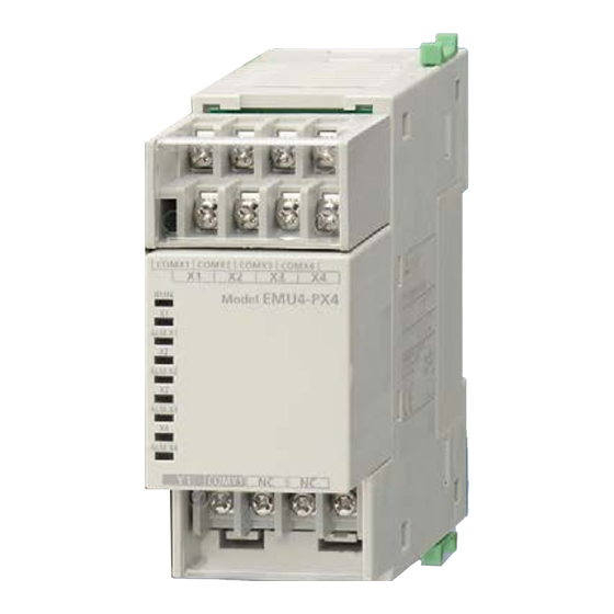
Energy Measuring Unit Extension for Pulse Input
Energy Measuring Unit Extension for Analog Input
Model
EMU4-PX4 / EMU4-AX4
User's Manual (Digest)
• Before using this unit, please read both this manual and Details carefully and pay attention to safety to handle this unit correctly.
• Make sure that the end users read this manual and then keep the manual in a safe place for future reference.
ABOUT MANUALS
You can download User's manual (Details) of this unit from the following site.
http://www.mitsubishielectric.com/fa/worldwide/index.html
1. Features
1.1 Pulse Input Unit
• This unit is an optional device dedicated to Energy Measuring Unit (EcoMonitorPlus).
• Adding this unit enables measurement of 4 circuits pulse.
• Monitor upper limit of data, and indicate LED and output signal at time beyond the setting upper limit level.
1.2 Analog Input Unit
• This unit is an optional device dedicated to Energy Measuring Unit (EcoMonitorPlus).
• Adding this unit enables measurement of 4 circuits analog input (0 to +5V/0 to +20mA).
• Monitor upper/lower limit of data, and indicate LED and output signal at time beyond the setting upper/lower limit level.
MODBUS is a trademark of Schneider Electric USA Inc.
2. Checking package contents
This following items for this device and included in package. Check that no items are missing.
(1) Energy Measuring unit x1
(2) User's Manual (Digest) x1
3. Safety Precautions
3.1 Precautions for Operating Environment and Conditions
(Note)
This unit is premised on being used in pollution degree 2
environment. When used in higher pollution degree, protect this unit from pollution on another device side to be
incorporated.
(Note)
Over voltage category of measuring circuit in this unit is CAT III
Do not use this product in the places listed below. Failure to follow the instruction may cause malfunctions and a life decrease of product.
• Places the Ambient temperature exceeds the range -5 to +55°C.
•
A
i t l
u t
d
e
e
c x
e
e
d
s
2
0
0
0
m
.
• Places in strong electromagnetic field or places large amounts of external noise exist.
•
P
a l
c
e
s
e
p x
o
s
e
d
o t
i d
e r
t c
u s
n
g i l
t h
•
P
a l
c
e
s
e
p x
o
s
e
d
o t
a r
n i
r o
w
t a
r e
d
o r
. p
This unit is the open type device, which are designed to be housed within another device for prevention of electric shock. House this unit within the device such as the control
panel before use. (Indoor use)
For the precautions for the compliance of the system incorporating this unit with the EMC Directives, refer to the User's Manual (Details).
(Note) For the definition of the pollution degree and the over voltage category, refer to EN61010-1/2010.
3.2 Matters concerning the precaution before use
• Use the unit in the specified usage environment and conditions.
• To use this unit, Base unit (EMU4-BM1-MB EMU4-HM1-MB EMU4-LG1-MB, EMU4-CNT-MB) is necessary. As for Base unit, refer to User's manual (Details) of each Base unit.
• To set this unit, dedicated small-size display unit (EMU4-D65) is necessary. For the setting method, refer to User's manual (Details) of the display unit.
3.3 Installation and Wiring Precautions
• Shut off the external power supply for the unit in all phases before installing or wiring. Failure to do so may cause an electric shock or damage of
this unit.
Danger
• Work under the electric outage condition when installing and wiring. Failure to do so may cause electric shock, a failure of the unit, a fire etc.
• Any person who is involved in the installation and the wiring of this unit should be fully competent to do this work.
• Keep the space around this product (all directions except the back) is 30 mm or more (100 mm or more for UL standard compliance).
• When tapping or wiring, take care not to entering any foreign objects such as chips and wire pieces into this unit.
• Check the connection diagram when wiring. Wrong wiring may cause failure of the unit, a fire or electric shock.
• This equipment is class A as per EN 55011. This equipment is not intended for use in residential environments and may not provide adequate protection to radio reception in
such environments.
• For protection against noise, transmission lines and input/output lines shall not be placed close to or bound together with the power lines and high-voltage lines.
• Strip the wires with proper length. Overlong stripping length may cause short to next wire and electric shock. Shorter stripping length may cause contact failure.
• Take care not to short to next terminal by a filament. (Do not plate the wires with solder.)
• Do not connect more than two wires to one terminal screw of a terminal block for preventing loose contact and wires dropout.
• Use appropriate size of electric wires. If inappropriate size of electric wire is used, it may cause a fire due to generated heat.
• Tighten the screw within the specified torque. Under tightening can cause drop of the screw, short circuit or malfunction. Over tightening can damage the screw and/or unit, resulting in
drop, short circuit or malfunction.
Caution
• After tightening the screws, be sure to check all the screws tightened. Loose screw may cause malfunction of the unit, a fire or electric shock.
• Be sure to attach the terminal cover to prevent electric shock.
• Use the crimp-type terminal appropriated for the size of electric wires. If inappropriate crimp-type terminal is used, a wire breakage or a contact failure may occur, which may cause a
device malfunction, a failure, a burnout or a fire.
• FG terminal must be grounded according to the D-type ground (ground resistance is not exceed 100Ω).
• Do not directly touch any conductive part of the unit. Doing so can cause electric shock, failure or malfunction of the unit.
• The wires to be connected to this unit shall be placed in a duct or fixed together by cramping. If the electric wires are not placed in the duct or cramped together, loosen wires or their
movement or careless stretch may cause a breakage of the unit or wire or a malfunction due to poor contact of electric wires.
• If the wires connected to this unit are strongly pulled off, it may cause a malfunction or a breakage to the unit or the wire.
• Do not exceed the specified voltage when doing an insulation resistance test and a commercial frequency withstand voltage test.
• To prevent persons with little knowledge about electric equipment from electric shock, panel must be taken either following measure.
Lock the panel so that only those who get an education about electric equipment and have sufficient knowledge can unlock, or shut off power supply automatically by opening the panel.
Cover the dangerous part of this unit.
3.4 Precautions for Use
• When use Energy Measuring Unit Analog Input Model (Model:EMU4-AX4)/ Energy Measuring Unit Pulse Input Model (Model:EMU4-PX4) with CC-link communication
unit(Model:EMU4-CM-C) and base unit(EMU4-BM1-MB, EMU4-HM1-MB, EMU4-LG1-MB), number of connectable show in the tables below.
① How to check the version for base unit
② Number of connectable Extension Unit
(ⅰ) With CC-Link Communication Unit
19R004
316 A 0066o
Version
If you are considering using this unit for special purpose such as nuclear power
plants, aerospace, medical care or passenger vehicles please refer to our sales
representative.
(Note)
, and that of auxiliary power circuit (MA, MB) is CAT III
.
• Places the average daily temperature exceeds +35°C.
•
D
u
s
, t
c
r o
o r
i s
e v
g
a
, s
s
a
n i l
e
a
n
d
i o
s l
m
o
k
e
e
x
s i
. t
• Vibration and impact exceed the specifications.
•
P
a l
c
e
s
m
e
a t
f l
a r
g
m
e
n
s t
r o
c
o
n
d
u
c
v i t
e
s
u
b
s
a t
c n
e
a
e r
y l f
n i
. g
•
P
a l
c
e
s
h t
e
R
e
a l
v i t
e
h
u
m
d i
y t i
e
c x
e
e
d
s
h t
e
a r
n
g
e
3
0
o t
8
5
%
r o
p
(ⅱ) Without CC-Link Communication Unit
(Model:EMU4-CM-C)
(Model:EMU4-CM-C)
Base unit
Base unit
Number of connectable
Number of connectable
Version
Version
A
2 units
A
later B
3 units
later B
• Use this unit within the ratings specified in this manual. If it is used outside the ratings, it may cause not only malfunction or failure but also fire burnout.
• Do not disassemble or modify this unit. It may cause failure, malfunction, injury or fire.
Caution
• Do not touch the live part such as connection terminal. It may cause electric shock, electric burn injury or burnout of the device. If any exposed conductor is found, stop the operation
immediately, and take an appropriate action such as isolation protection.
3.5 Maintenance Precautions
• Use a soft dry cloth to clean off dirt of the unit surface. Do not let a chemical cloth remain on the surface for an extended period of time nor wipe the surface with thinner or
benzene.
• Check for the following items to use this unit properly for long time.
(1) Daily maintenance
(
) a
N
o
d
a
m
a
g
e
o
n
(2) Periodical maintenance (Once every 6 months to 1 year)
• No looseness with installation and wire connection
Do periodical maintenance under the electric outage condition. Failure to do so may cause electric shock, failure of the unit or a fire. Tighten the terminal regularly to prevent a fire. In case
Caution
a display unit is attached to a sensor unit, get off the display unit during maintaining or tightening terminals.
3.6 Storage Precautions
To store this unit, turn off the power and remove wires, and put it in a plastic bag.
For long-time storage, avoid the following places. Failure to follow the instruction may cause a failure and reduced life of the unit.
• Places the Ambient temperature exceeds the range -10 to +60°C.
• Places the Relative humidity exceeds the range 30 to 85% or places with dewfall.
•
D
u
s
, t
c
r o
o r
s
v i
e
g
a
, s
• Places the average daily temperature exceeds +35°C.
3.7 Disposal Precautions
When disposing of this unit, treat it as industrial waste.
3.8 About packaging materials and this manual
For reduction of environment load, packaging materials are produced with cardboard.
4. Name and function of each part
4.1 Name of each part
(
) 1
E
M
U
4
P -
X
4
External input terminals (X1 to X4、COMX1 to COMX4)
Connect to pulse / contact input.
LED
Operation mode is
displayed.
(Please reference to 4.2
Indication and functions
of LEDs)
Connector (male)
Connect to the energy
measuring unit.
a l
c
e
s
i w
h t
d
e
w
a f
. l l
External output terminals (Y1, COMY1)
Connect the contact output wire.
4.2 Indication and functions of LEDs
The names and operations of LEDs are as follows.
(1) EMU4-PX4
N
a
m
e
C
l o
r o
F
u
n
Red
Indicate operating status of this unit.
RUN LED
Red
Indicate measuring status of the circuit X1.
X1 LED
Red
Indicate occurrence status of upper limit
ALM. X1 LED
alert of the circuit X1.
Red
Indicate measuring status of the circuit X2.
X2 LED
Red
Indicate occurrence status of upper limit
ALM. X2 LED
alert of the circuit X2.
Red
Indicate measuring status of the circuit X3.
X3 LED
Red
Indicate occurrence status of upper limit
ALM. X3 LED
alert of the circuit X3.
Red
Indicate measuring status of the circuit X4.
X4 LED
Red
Indicate occurrence status of upper limit
ALM. X4 LED
alert of the circuit X4.
(Note 1) For details, refer to Chapter 14 "Error codes" of "User's Manual (Details)".
5. Connecting to Base unit
(1) Peel off the label pasted right part of
measure unit.
Blank label
3 units
3 units
h t
s i
u
n
t i
(
) b
N
o
a
b
n
r o
m
l a
y t i
i w
h t
L
E
D
• Vibration and impact exceed the specifications.
• Places exposed to rain, water drop or direct sunlight.
s
a
n i l
e
a
n
d
i o
s l
m
o
k
e
e
x
s i
. t
•
P
a l
c
e
(
) 2
E
M
U
4
A -
X
4
Analog input terminals (AX1 to AX4、COMAX1 to COMAX4)
Connect to analog input.
LED
Operation mode is
displayed.
(Please reference to 4.2
Indication and functions
of LEDs)
Connector (male)
Connect to the energy
measuring unit.
Frame GND(FG)
External output terminals (Y1, COMY1)
Connect to ground
Connect the contact output wire.
(D type ground)
(2) EMU4-AX4
t c
o i
n
S
a t
u t
s
N
a
m
e
ON: Normal condition
RUN LED
OFF: Power off or hardware failure (Note 1)
ON: Contact state is ON
AX1 LED
Blink: In the middle of measuring the pulse
OFF: Other
ALM. AX1 LED
ON: An error occurs (Note 1)
Blink: Upper limit alert is issued
OFF: No alert
AX2 LED
ON: Contact state is ON
Blink: In the middle of measuring the pulse
ALM. AX2 LED
OFF: Other
ON: An error occurs (Note 1)
Blink: Upper limit alert is issued
AX3 LED
OFF: No alert
ON: Contact state is ON
ALM. AX3 LED
Blink: In the middle of measuring the pulse
OFF: Other
ON: An error occurs (Note 1)
AX4 LED
Blink: Upper limit alert is issued
OFF: No alert
ALM. AX4 LED
ON: Contact state is ON
Blink: In the middle of measuring the pulse
OFF: Other
ON: An error occurs (Note 1)
Blink: Upper limit alert is issued
OFF: No alert
(2) Plug connector (male) to connector (female) of
(3) Lock the measure unit to slide consolidated
measure unit for brought into close contact.
EMU4-BM1-MB
MODEL
(
) c
N
o
a
b
n
r o
m
l a
n
o
s i
, e
s
m
l l e
r o
h
e
t a
s
m
e
a t
f l
a r
g
m
e
n
s t
r o
c
o
n
d
u
c
v i t
e
s
u
b
s
a t
n
c
e
a
e r
y l f
n i
. g
(
) 3
B
a
k c
a
n
d
r
g i
t h
s
d i
e
c (
o
m
m
o
n
o t
E
M
U
4
P -
X
4
a
n
d
E
M
U
4
A -
Connector (female)
Connect extension units.
IEC rail fixture
Connection stop
This is used to connect the
extension unit
C
l o
r o
F
u
c n
i t
n o
t S
t a
s u
Red
Indicate operating status of this unit.
ON: Normal condition
OFF: Power off or hardware failure (Note 1)
Red
Indicate measuring status of the
ON: In the middle of measuring
circuit AX1.
OFF: Other
Red
Indicate occurrence status of upper
ON: An error occurs (Note 1)
limit alert of the circuit AX1.
Blink: Upper/lower limit alert is issued
OFF: No alert
Red
Indicate measuring status of the
ON: In the middle of measuring
circuit AX2.
OFF: Other
Red
Indicate occurrence status of upper
ON: An error occurs (Note 1)
limit alert of the circuit AX2.
Blink: Upper/lower limit alert is issued
OFF: No alert
Red
Indicate measuring status of the
ON: In the middle of measuring
circuit AX3.
OFF: Other
Red
Indicate occurrence status of upper
ON: An error occurs (Note 1)
limit alert of the circuit AX3.
Blink: Upper/lower limit alert is issued
OFF: No alert
Red
Indicate measuring status of the
ON: In the middle of measuring
circuit AX4.
OFF: Other
Red
Indicate occurrence status of upper
ON: An error occurs (Note 1)
limit alert of the circuit AX4.
Blink: Upper/lower limit alert is issued
OFF: No alert
(Note 1) EMU4-BM1-MB,
claws (green).
EMU4-HM1-MB, EMU4-LG1-MB,
EMU4-CNT-MB are the
connectable unit.
(Note 2) The number of extension
units that can be connected to one
base unit depends on the connection
the product version and the CC-Link
communication
unit
of
the
unit.(3.4 Precautions for Use)
Caution
Work under the electric outage
condition when connecting the
Extension units. Failure to do so
may cause electric shock, a
failure of the unit, a fire etc.
X
) 4
base
Advertisement

Related Manuals for Mitsubishi Electric EMU4-PX4


Summary of Contents for Mitsubishi Electric EMU4-PX4
- Page 1 (3) Lock the measure unit to slide consolidated (Note 1) EMU4-BM1-MB, • When use Energy Measuring Unit Analog Input Model (Model:EMU4-AX4)/ Energy Measuring Unit Pulse Input Model (Model:EMU4-PX4) with CC-link communication measure unit. measure unit for brought into close contact.
- Page 2 This is an example of 3P3W low voltage circuit. This is an example of the system with Base unit EMU4-HM1-MB Power supply side Item Specifications and Extension unit EMU4-PX4 for 3P4W use with Current Base unit: EMU4-BM1-MB System 1 System 2 Extension unit 1: EMU4-A2 Instrument transformer transformer or voltage transformer.
Need help?
Do you have a question about the EMU4-PX4 and is the answer not in the manual?
Questions and answers