Table of Contents
Advertisement
Quick Links
Advertisement
Table of Contents

Subscribe to Our Youtube Channel
Related Manuals for Bosch D125B


Summary of Contents for Bosch D125B
- Page 1 Powered loop interface D125B Installation instructions...
- Page 3 Powered loop interface Notices | en Notices These instructions cover the installation of the D125B Dual Class B Initiating Module in a fire system supervised by a fire alarm control panel (FACP) or a combination Burglary/Fire control panel. Before installing the module, become familiar with the Installation and Operation Guide for the control panel you are using.
-
Page 4: Operation
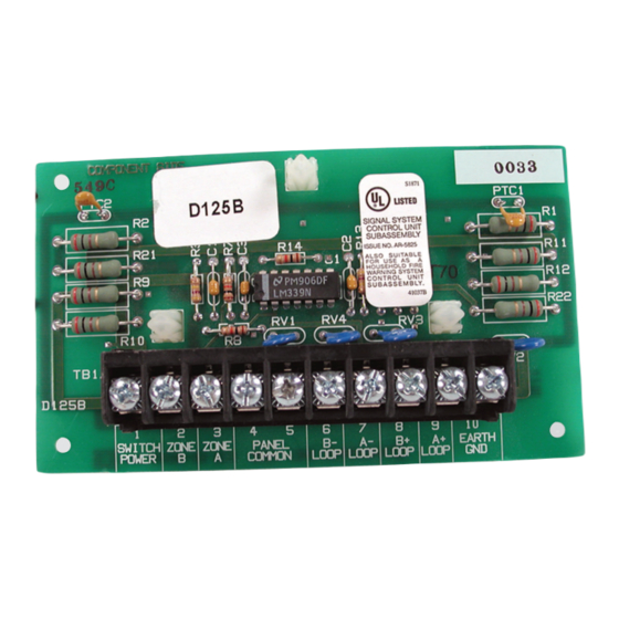
* Legacy products have not been investigated to comply with the latest UL864 edition. ** indicates products which are not UL Listed for commercial fire applications. Figure 2.1: D125B Powered loop interface 1 Power-limited, supervised switched 2 Supervised connection to protective... -
Page 5: Installation
The other enclosures have several module mounting locations to which the module can be installed using the supplied screws. Refer to the D137’s and the enclosure’s Installation Instructions for mounting locations and instructions. Bosch Security Systems, Inc. Installation instructions 2018.06 | 4.0 | F.01U.036.340... - Page 6 N: F01U009011B) supplied with the module The D125B shorts the protective loop on the control panel when the high (+) and low (-) side of either module loop is shorted together or when a smoke detector activates. The module opens the protective loop on the control panel during the following conditions: –...
- Page 7 11 Output A jumper (under cover) set for auxiliary power applications (AUX PWR) You can also use output B or C in conjunction with a D133 or D134 relay module. Bosch Security Systems, Inc. Installation instructions 2018.06 | 4.0 | F.01U.036.340...
-
Page 8: Power Supply
Use either a 12 VDC or 24 VDC regulated, power‑limited auxiliary power supply listed under UL864 or UL1481. Notice! Do not mix 12 VDC and 24 VDC detectors on the same module. 2018.06 | 4.0 | F.01U.036.340 Installation instructions Bosch Security Systems, Inc. - Page 9 10 Earth ground loop detectors (see Wiring sensor loops, page 6) 11 Output A (NC) of the control panel 12 For 24 V applications, cut this wire controls the relay Bosch Security Systems, Inc. Installation instructions 2018.06 | 4.0 | F.01U.036.340...
- Page 10 6) 7 Power-limited, supervised negative to 8 Power-limited, supervised positive to B A loop detectors (see Wiring sensor loop detectors (see Wiring sensor loops, page 6) loops, page 6) 2018.06 | 4.0 | F.01U.036.340 Installation instructions Bosch Security Systems, Inc.
-
Page 11: Specifications
< 3.5 mA < 7.5 mA Loop wire resistance 50 Ω 50 Ω Environmental Environment Indoor, dry Operating Temperature +32°F to +122°F (0°C to +50°C) Relative Humidity 5% to 93% at +86°F (+30°C); non-condensing Bosch Security Systems, Inc. Installation instructions 2018.06 | 4.0 | F.01U.036.340... - Page 12 Dimensions (H x W x D) 5 in. x 3 in. x 0.8 in. (12.7 cm x 7.6 cm x 2.0 cm) Compatible detectors and modules Compatible 2‑wire detectors Underwriters Laboratories (UL) has found the following 2‑wire detectors to be compatible with the D125B: Manufacturer Series Base Reversing* Maximum number of detectors per loop 12 V...
-
Page 13: Compatible Modules
D132A reversing relay* ● ● D133 ● D134 ● * D132A does not operate at 24 V; use only on 12 V powered loops. ** Relay can switch 24 V, but operates at 12 V. Bosch Security Systems, Inc. Installation instructions 2018.06 | 4.0 | F.01U.036.340... - Page 16 Bosch Security Systems, Inc. Bosch Sicherheitssysteme GmbH 130 Perinton Parkway Robert-Bosch-Ring 5 Fairport, NY 14450 85630 Grasbrunn Germany www.boschsecurity.com © Bosch Security Systems, Inc., 2018...
Need help?
Do you have a question about the D125B and is the answer not in the manual?
Questions and answers