Table of Contents
Advertisement
Quick Links
Advertisement
Table of Contents

Related Manuals for Hunter Hydrawise 10021300SP


Summary of Contents for Hunter Hydrawise 10021300SP
- Page 1 HC Flow Meter HYDRAWISE-READY QUICK START GUIDE...
-
Page 2: Table Of Contents
HC Support Thank you for purchasing the Hunter HC Flow Meter. In this Quick Start Guide, you'll learn how to install and configure your flow meter. If you need Hydrawise Software support or help with your Hydrawise account, visit hunter.help/hydrawise. -
Page 3: Box Contents
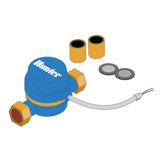
Box Contents ADAPTER FITTINGS GASKETS FLOW METER *Shielded direct-burial cable must be used for installation. Note: This product is intended for use with PART NUMBER DESCRIPTION professional-grade materials. It must be 10021300SP Qty. 10, HC-075-FLOW Spare Gaskets installed by a licensed irrigation contractor or 10021400SP Qty. -
Page 4: Hc Flow Meter Measuring
HC Flow Meter Measuring The flow meter consists of two parts: 1. Flow meter body: The flow meter body contains an analog dial for manual readings as follows. Your flow meter will have three wires protruding from the body. The wires need to be connected to the sensor inputs on the controller for readings in the software application. -
Page 5: Planning
Planning Planning is an important step in the successful installation of your Hunter HC Flow Meter and the reliable operation of your irrigation system. 3. Flow meter location: Flow meters are installed between the master valve and the zone valves. To avoid false alerts, there should be no water taps or other uncontrolled water use on the downstream side of the flow meter. - Page 6 WIRE SIZE MAX LENGTH available. Manufacturers include Paige Electric Gauge Feet and Regency Wire. 1,000 Flow meters can be potentially damaged by blow SCAN out winterization. Either remove flow meter prior for help to winterization or use a bypass. hunter.help/winterization...
-
Page 7: Installing
Installing Use the following instructions if your Hunter controller with Hydrawise Software has already been installed. 1. Install the flow meter: The body of the flow meter includes an arrow-shaped marking that indicates the direction of the water flow. The flow meter must be installed in the correct orientation with the water flowing in the same direction as the arrow on the flow meter body. - Page 8 The general rule is that 0.5 mm (20 GA) wire is ideal for a run of up to 240'. Connect the wires to your Hydrawise-enabled Hunter controller.
-
Page 9: Configuring
1" flow meter 1 pulse per 1 gal 1 1/2" 11/ 2" flow meter 1 pulse per 1 gal 2" 2" flow meter 1 pulse per 1 gal 3. Assign zones to the flow sensor: Refer to hunter.help/hydrawise for app/software setup information. -
Page 10: Troubleshooting
Troubleshooting Need more helpful information on your product? Find tips on installation, controller programming, and more using the resources below. SCAN for help hunter.help/hydrawise SCAN for help hydrawise.com/flowmeterinstall... - Page 11 Notes...
- Page 12 Built on Innovation® Learn more. Visit hunterindustries.com © 2023 Hunter Industries Inc. Hunter, the Hunter logo, and other marks are trademarks of Hunter Industries Inc., registered in the U.S. and certain other countries. LIT 694 QG FlowMeter US E 4/23...
Need help?
Do you have a question about the Hydrawise 10021300SP and is the answer not in the manual?
Questions and answers