Table of Contents
Advertisement
Quick Links
Advertisement
Table of Contents

Related Manuals for Trane 4TVH0086B6000AB


Summary of Contents for Trane 4TVH0086B6000AB
- Page 1 Technical Service Manual Model:...
-
Page 3: Part 1 General Information
Part 1 General Information 1. Product lineup ..................2 2. Features ....................2 3. Indoor units lineup .................. 6 General Information... -
Page 4: Product Lineup
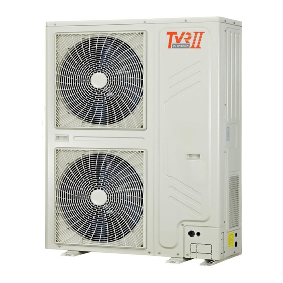
1. Product lineup Model Capacity External appearance Power Supply 4TVH0086B6000AB 25.2kW (8HP) 220-240V-3N~60Hz 4TVH0096B6000AB 28kW (10HP) 2. Features 2.1 Wide application range 2.1.1 Wide capacity range The Capacity range of side discharge type is from 20kW to 45kW, which is designed to optimize performance and better match varieties of application requirement. - Page 5 2.2 High efficiency 2.2.1 High efficiency DC inverter compressor High efficiency DC inverter twin rotary compressor Highly Efficient DC Motor: - Creative motor core design - High density neodymium magnet - Concentrated type stator -Wider operating frequency range Better balance and Extremely Low Vibration: - Twin eccentric cams - 2 balance weights Highly Stable Moving Parts:...
- Page 6 2.3.2 Night silent operation mode Trane's Night Silent Mode feature which is easily set on the PCB board allows the unit to be set to vary time options during Non-Peak and Peak operation time optimizing the units noise output.
- Page 7 2.4 Easy installation and service 2.4.1 Compact design for effective use of space Easy to transport Compact size and light weight design minimizes the installation footprint, reduces the installation floor load, and easier for transportation. For some projects the units can even be transported through the elevator or forklift, lessen access problem at the jobsite.
-
Page 8: Indoor Units Lineup
3. Indoor units lineup Cassette type Compact four-way One-way cassette Two-way cassette Four-way cassette Capacity cassette (×100W) Duct type Low static A5 duct High static pressure duct Capacity pressure duct (×100W) General Information... - Page 9 Indoor units lineup Floor-standing/Ceiling & Floor/Console Cased floor-standing Uncased floor-standing Ceiling & floor Wall mounted(M panel) Capacity (×100W) Note: 1、 Due to continuous improvement, specifications are subject to change without prior notice. General Information...
-
Page 10: Table Of Contents
Part 2 Specifications & Performance 1. Specifications ..................9 2. Dimensions .................... 13 3. Service space ..................14 4. Piping diagrams ..................16 5. Wiring diagram ..................18 6. Electric characteristics ................. 20 7. Capacity tables ..................21 8. Sound levels ..................61 9. -
Page 11: Specifications
1. Specifications Model 4TVH0086B6000AB 4TVH0096B6000AB Power supply V-Ph-Hz 220V,3Ph,60Hz 220V,3Ph,60Hz Capacity 25.2 Cooling Power input 3.71 3.59 Capacity 31.5 Heating Power input 4.22 4.14 Model LNB53FCFMC LNB53FCFMC Type Rotary Rotary Brand MITSUBISHI MITSUBISHI Quantity Compressor Capacity 26.9 26.9 Input Crankcase heater... - Page 12 Net/Gross weight 147/163 147/163 Type R410A R410A Refrigerant Factory charged Throttle type Electronic expansion valve Electronic expansion valve Design pressure (Hi/Lo) 4.4/2.6 4.4/2.6 Ф9.53 Ф9.53 Liquid pipe Refrigerant piping Ф22.2 Ф22.2 Gas pipe Cooling -5~48 -5~48 Ambient temp. range Heating -15~24 -15~24 Notes:...
-
Page 13: Dimensions
2. Dimensions 4TVH0086B6000AB 4TVH0096B6000AB Unit: mm 1120 205.8 Specifications & Performance... -
Page 14: Service Space
3. Service space 4TVH0086B6000AB 4TVH0096B6000AB Single unit installation (Wall or obstacle) Air inlet >300 Maintain the electric wire and pipeline Air inlet >600 Air outlet Multiple unit installation >300 >600 >3000 >6000 >3000 >1000 >4000 >300 Specifications & Performance... -
Page 15: Piping Diagrams
4. Piping diagrams 4TVH0086B6000AB 4TVH0096B6000AB Key components: Oil separator: It is used to separate oil from high pressure and high temperature gas refrigerant, which is pumped out from compressor. The separation efficiency is up to 99%, it makes the oil return back to each compressor very soon. -
Page 16: Wiring Diagram
5 Wiring diagram 4TVH0086B6000AB Specifications & Performance... - Page 17 4TVH0096B6000AB Specifications & Performance...
-
Page 18: Electric Characteristics
6. Electric characteristics Unit Power supply Compressor Model Voltage Min. Max. TOCA 37.8 4TVH0086B6000AB 0.17×2 2.1+1.7 37.8 4TVH0096B6000AB 0.17×2 2.1+1.7 Notes: 1. RLA is based on the following conditions, Indoor temp. 27° C DB/19° C WB, Outdoor temp. 35° C DB 2. -
Page 19: Capacity Tables
7. Capacity tables 7.1 Cooling capacity tables 4TVH0086B6000AB TC: Total Capacity (kW); PI: Power Input (kW) (Compressor + Outdoor fan motor) Indoor temperature( C DB/WD) Outdoor 20.8/14 23.3/16 25.8/18 27/19 28.2/20 30.7/22 32/24 Combination temp. 17.6 2.49 20.9 3.04 24.3 3.26... - Page 20 Cooling capacity tables 4TVH0086B6000AB TC: Total Capacity (kW); PI: Power Input (kW) (Compressor + Outdoor fan motor) Indoor temperature( C DB/WD) Outdoor 20.8/14 23.3/16 25.8/18 27/19 28.2/20 30.7/22 32/24 Combination temp. 14.9 2.10 17.7 2.62 20.6 3.12 22.0 3.35 23.4 3.61...
- Page 21 Cooling capacity tables 4TVH0086B6000AB TC: Total Capacity (kW); PI: Power Input (kW) (Compressor + Outdoor fan motor) Indoor temperature( C DB/WD) Outdoor 20.8/14 23.3/16 25.8/18 27/19 28.2/20 30.7/22 32/24 Combination temp. 12.1 1.69 14.5 2.03 16.9 2.40 18.0 2.62 19.1 2.78...
- Page 22 Cooling capacity tables 4TVH0086B6000AB TC: Total Capacity (kW); PI: Power Input (kW) (Compressor + Outdoor fan motor) Indoor temperature( C DB/WD) Outdoor 20.8/14 23.3/16 25.8/18 27/19 28.2/20 30.7/22 32/24 Combination temp. 1.33 11.3 1.56 13.1 1.77 14.0 1.90 14.9 2.03 16.7...
- Page 23 Cooling capacity tables 4TVH0086B6000AB TC: Total Capacity (kW); PI: Power Input (kW) (Compressor + Outdoor fan motor) Indoor temperature( C DB/WD) Outdoor 20.8/14 23.3/16 25.8/18 27/19 28.2/20 30.7/22 32/24 Combination temp. 0.99 1.14 1.31 10.0 1.37 10.6 1.45 11.9 1.65 13.3...
- Page 24 Cooling capacity tables 4TVH0086B6000AB TC: Total Capacity (kW); PI: Power Input (kW) (Compressor + Outdoor fan motor) Indoor temperature(° C) Combinatio DB:23.3,WB:1 DB:25.8,WB:1 DB:27,WB:1 DB:28.2,WB:2 DB:30.7,WB:2 DB:32,WB:2 Outdoor DB:20.8,WB:14 n (%) temperatur (Capacity e(° C DB) index) 22.40 2.65 26.80 3.16...
- Page 25 21.52 3.42 25.22 4.08 25.73 4.82 28.07 5.04 28.56 5.07 29.26 5.09 31.72 5.14 21.52 3.66 25.22 4.37 25.73 5.15 27.80 5.38 28.29 5.42 28.98 5.44 31.42 5.49 21.52 3.91 25.22 4.66 25.73 5.50 27.53 5.75 28.01 5.79 28.70 5.81 31.12 5.86 21.52...
- Page 26 16.23 1.87 19.02 2.16 19.40 2.52 20.16 2.63 20.51 2.65 21.02 2.66 22.79 2.69 16.23 1.90 19.02 2.20 19.40 2.56 20.16 2.68 20.51 2.70 21.02 2.71 22.79 2.73 16.23 1.94 19.02 2.24 19.40 2.61 20.16 2.73 20.51 2.74 21.02 2.76 22.79 2.78 16.23...
- Page 27 12.17 2.31 14.27 2.80 14.55 3.23 15.12 3.26 15.38 3.28 15.76 3.30 17.09 3.32 12.17 2.32 14.27 2.82 14.55 3.25 15.12 3.27 15.38 3.30 15.76 3.31 17.09 3.34 10.14 0.92 11.89 1.12 12.13 1.29 12.60 1.30 12.82 1.31 13.14 1.32 14.24 1.33 10.14...
- Page 28 Cooling capacity tables 4TVH0096B6000AB TC: Total Capacity (kW); PI: Power Input (kW) (Compressor + Outdoor fan motor) Indoor temperature(° C) Combinatio DB:20.8,WB:1 DB:23.3,WB:1 DB:25.8,WB:1 DB:27,WB:1 DB:28.2,WB:2 DB:30.7,WB:2 DB:32,WB:2 Outdoor n (%) temperature(° (Capacity C DB) index) 24.88 3.04 29.78 3.63 33.62 4.28 35.24...
- Page 29 23.91 3.93 28.02 4.68 28.59 5.53 31.18 5.78 31.73 5.82 32.51 5.84 35.25 5.89 23.91 4.20 28.02 5.01 28.59 5.91 30.89 6.17 31.43 6.22 32.20 6.24 34.91 6.30 23.91 4.48 28.02 5.35 28.59 6.31 30.59 6.59 31.13 6.64 31.89 6.67 34.58 6.72 23.91...
- Page 30 18.03 2.14 21.13 2.48 21.56 2.89 22.40 3.02 22.79 3.04 23.35 3.05 25.32 3.08 18.03 2.18 21.13 2.52 21.56 2.94 22.40 3.07 22.79 3.10 23.35 3.11 25.32 3.13 18.03 2.22 21.13 2.57 21.56 2.99 22.40 3.13 22.79 3.15 23.35 3.16 25.32 3.19 18.03...
- Page 31 13.52 2.65 15.85 3.22 16.17 3.71 16.80 3.74 17.09 3.77 17.51 3.78 18.99 3.81 13.52 2.66 15.85 3.23 16.17 3.73 16.80 3.76 17.09 3.78 17.51 3.80 18.99 3.83 11.27 1.06 13.21 1.28 13.48 1.48 14.00 1.49 14.25 1.50 14.60 1.51 15.82 1.52 11.27...
- Page 32 7.2 Heating capacity tables 4TVH0086B6000AB TC: Total Capacity (kW); PI: Power Input (kW) (Compressor + Outdoor fan motor) Indoor temperature(° C DB) Outdoor air Combination temp. (Capacity index) ° C DB ° C WB -14.7 19.31 5.28 19.31 5.49 19.12 5.74...
- Page 33 -5.6 19.73 5.41 19.63 5.62 19.44 5.82 18.67 5.92 17.90 5.96 16.74 6.04 -3.7 20.28 5.49 20.18 5.70 19.98 5.91 19.19 6.01 18.39 6.05 17.21 6.13 -0.7 20.83 5.61 20.73 5.83 20.52 6.03 19.71 6.14 18.89 6.18 17.67 6.26 23.45 5.73 23.33 5.95...
- Page 34 -8.5 -9.1 16.44 2.61 16.36 2.69 16.20 2.77 15.56 2.79 14.91 2.81 13.95 2.85 -7.6 16.44 2.64 16.36 2.72 16.20 2.80 15.56 2.82 14.91 2.84 13.95 2.88 -5.6 16.44 2.68 16.36 2.76 16.20 2.85 15.56 2.86 14.91 2.88 13.95 2.92 -3.7 16.44 2.71...
- Page 35 Heating capacity tables 4TVH0096B6000AB TC: Total Capacity (kW); PI: Power Input (kW) (Compressor + Outdoor fan motor) Indoor temperature(° C DB) Outdoor air Combination temp. (Capacity index) ° C DB ° C WB -14.7 22.53 6.27 22.53 6.51 22.30 6.82 21.64 6.86 21.42...
- Page 36 -5.6 23.02 6.43 22.91 6.68 22.68 6.91 21.78 7.03 20.88 7.08 19.53 7.17 -3.7 23.66 6.52 23.54 6.77 23.31 7.01 22.39 7.14 21.46 7.18 20.08 7.28 -0.7 24.30 6.66 24.18 6.92 23.94 7.17 22.99 7.29 22.04 7.34 20.62 7.43 27.35 6.80 27.22 7.07...
- Page 37 -8.5 -9.1 19.18 3.10 19.09 3.19 18.90 3.29 18.15 3.31 17.40 3.34 16.28 3.38 -7.6 19.18 3.13 19.09 3.23 18.90 3.33 18.15 3.35 17.40 3.37 16.28 3.42 -5.6 19.18 3.18 19.09 3.28 18.90 3.38 18.15 3.40 17.40 3.42 16.28 3.47 -3.7 19.18 3.22...
-
Page 38: Sound Levels
8. Sound levels Side air discharge type Front 1.3m Notes: • Data is valid at free field condition • Data is valid at nominal operating condition • Sound level will vary depending on a range of factors such as the construction (acoustic absorption coefficient) of particular room in which the equipment is installed •... -
Page 39: Sound Pressure Level
Sound pressure level Sound pressure level Model d(B)A 4TVH0086B6000AB 4TVH0096B6000AB Sound pressure spectrum 25.2kW 28kW Audibility limits of Audibility limits of continuous white sound continuous white sound 125 250 500 1000 2000 4000 8000 125 250 500 1000 2000 4000... -
Page 40: Accessories
9. Accessories 9.1 Standard accessories 4TVH0086B6000AB 4TVH0096B6000AB Specifications & Performance... - Page 41 9.2 Optional accessories Branch joint of outdoor & indoor unit Gross/net Optional accessories Model name Packing Size (mm) Function Weight (kg) TODK002HP 255×150×185 1.5/1.2 Branch Joint of outdoor TODK003HP 345×160×285 3.4/2.4 unit TODK004HP 475×165×300 4.8/3.6 Distribute the refrigerant to TRDK056HP 290×105×100 0.4/0.3 Indoor Units and balance the...
- Page 43 Part 3 Installation 1. Select installation position ..............66 2. Foundation for installation ..............66 3. Installation space .................. 67 4. Lifting method ..................69 5. Refrigerant piping installation .............. 69 6. Branch pipe installation ................ 73 7. Remove dirt or water in the piping ............73 8.
-
Page 44: Select Installation Position
1. Select installation position Ensure that the outdoor unit is installed in a dry, well-ventilated place. Ensure that the noise and exhaust ventilation of the outdoor unit do not affect the neighbors of the property owner or the surrounding ventilation. ... -
Page 45: Installation Space
3. Installation space 4TVH0086B6000AB 4TVH0096B6000AB Single unit installation (Wall or obstacle) Air inlet >300 Maintain the electric wire and pipeline Air inlet >600 Air outlet Multiple unit installation >300 >600 >3000 >3000 >1000 >6000 >4000 >300 Installation... -
Page 46: Lifting Method
4. Lifting method Do not remove any package before the hoisting. Use two ropes to hoist the machine, keep the machine in balance, and then raise it safely and steadily. In case of no package or if the package is damaged, use plates or packing material to protect it. - Page 47 5.2 Refrigerant piping length permitted value The first connecting method Outdoor unit Pipe Length(from the nearest branch pipe equivalent length Maximum pipe equivalent length The first line Branch Pipe (from the first line branch pipe) Maximum pipe equivalent length Indoor Unit ...
- Page 48 5.3 Refrigerant piping selection The first connecting method The second connecting method Pipe name Main pipe Indoor unit main pipe L2, L3, L4, L5 Indoor unit branch pipe a, b, c, d, e, f Indoor unit branch pipe assembly A, B, C, D, E ...
- Page 49 Table 3: Main pipe selection (L1) When the equivalent length of all liquid and air When the equivalent length of all liquid and pipes ≥90m air pipes < 90m Model Gas side Liquid side The 1 branch Gas side Liquid side The 1 (mm)
-
Page 50: Branch Pipe Installation
6. Branch pipe installation The branching pipe must be installed horizontally and error angle of it should not be larger than 10° . Otherwise, refrigerant assignment will be uneven and malfunction will be caused. U-shaped branching pipe A direction view Wrong Correct 10°... -
Page 51: Additional Refrigerant Charge
Connect with vacuum pump Perform the pump (last for 2 hours or above) 1. Close-off the valve of vacuum meter. When get the vacuum level 2. Cut off the connection -0.1MPa, the pump should between pressure meter keep running for 20-60 mins and vacuum pump. - Page 52 same time, otherwise, the service life would affect seriously, even the unit may not turn on.) Please put the connective wiring system between indoor unit and outdoor unit with refrigerant piping system together. It is suggested to use 3-core shielded wire as signal wire between indoor and outdoor units, multi-core wire is unavailable. Please comply with relevant National Electric Standard.
-
Page 53: Running Test
12. Running test Operate according to “key points for test running” on the electric control box cover. CAUTION Test running cannot start until the outdoor unit has been connected to the power for 12hours. Test running cannot start until all the valves are affirmed open. ... -
Page 54: Outdoor Unit
Outdoor unit Indoor unit Room full of leak refrigerant (All refrigerant has run up) b. Leak alarm related to mechanical ventilator Indoor unit A. Ventilation peristome (Leak hunting siren should be installed in places easily keep refrigerant) NOTE Please press “Force Cool” button to carry out refrigerant recycling process. Keep the low pressure above 0.2MPa;... - Page 56 Part 4 Troubleshooting 1. Main PCB ports instructions ..............79 2. Main PCB parts instructions ..............82 3. Error code table ..................87 4. Troubleshooting..................89 Troubleshooting...
-
Page 57: Main Pcb Ports Instructions
1. Main PCB ports instructions 1.1 25.2/28kW models Ports instructions: Content Port voltage Power input port of the main PCB 220V Load output port (crankcase heater HAET 1&HEAT 2) 220V Load output port 220V Load output port 220V Load output port 220V Load output port (solenoid valve SV6 control) 220V... - Page 58 Setting switch of Setting switch of outdoor unit address outdoor unit ability setting switch of indoor unit quantity Force cooling keys Point checking keys...
- Page 59 Ports instructions: Content Port voltage Discharge temp detection port of inverter compressor A DC 0~5V (in dynamic change) Discharge temp detection port of inverter compressor B DC 0~5V (in dynamic change) Temp detection port of inverter module radiator DC 0~5V (in dynamic change) Reserved Reserved Wiring port for communication between indoor and outdoor units, indoor...
- Page 60 2. Main PCB parts instructions 2.1 25.2/28kW models Inverter compressor drive chip Main control chip Function setting dial switch SW1: forced cooling button SW2: check button Communication chip LED digital tube display 2.1.1 Check content instructions (SW2) Display content Display content Note Normal display Capacity of this outdoor unit...
- Page 61 1: Display compressor frequency when system is running and display the quantity of indoor unit which communicate with outdoor unit when system is standby. 2: Operating mode: 0 – standby mode; 2 – cooling mode; 3 – heating mode; 4 – forced cooling. 3: Fan speed: 0 –...
-
Page 62: Error Code Table
3. Error code table 3.1 25.2/28kW models Error code Content Note Reserved communication fault between the outdoor and indoor units T3 & T4 temperature sensor fault Voltage protection fault or a lack of Phase B、Phase N DC fan motor error Discharge temp sensor error A fan in the A region run for more than 5 minutes in Heat mode 2 times of E6 protection in 10 minutes... -
Page 63: Troubleshooting
Frequency difference in one second more than 15Hz protection Frequency difference between the real and the setting frequency more than 15Hz protection SW3 button (press SW3 ten times, every one second for a time) The large capacity individual system (56-90kW) have the function of refrigerant volume automatic judgment. - Page 64 4.2 E2: Indoor units and outdoor unit communication error E2: Indoor units and outdoor unit communication error Communication wires P, Q, E are Reconnect the communication short circuit or disconnected (Measure wires the resistance among P Q and E, the normal resistance is 120Ω) Connect the communication wires Communication...
- Page 65 4.3 E4: Pipe temp T3/ambient temp T4 sensor error; E7: Discharge temp sensor T7 error E4: T3/T4/T7 sensor error T3/T4/T7 port on main Fasten the T3/T4 port control board is loose T3/T4/T7 sensor is short circuit or disabled (Using a multimeter to Replace the sensor measure resistance, if the resistance is too small, the sensor is short circuit, if...
- Page 66 4.4 E5: Voltage error E5: Voltage error Voltage of power supply is too high or too low (the normal voltage between A Provide normal power supply and N (B and N, C and N) should be 163V~268V) Check the high voltage circuit. Whether the compressor is short circuit①, fan Replace the inverter module motor is short circuit②, inverter module...
- Page 67 4.5 E6: DC fan motor error; EB: E6 protection appears twice in 10 minutes E6: DC fan motor error There has strong airflow against fan It belongs to normal protection wheel when the fan is running DC fan wiring connection Wiring connection consists with wiring consistent with wiring nameplate nameplate...
- Page 68 4.6 EA: T3 pipe temperature protection in heating mode When T3 pipe temperature exceeds 27 C lasting for five minutes in heating mode, the unit will display EA error. EA: T3 pipe temperature protection in heating mode The outdoor ambient temperature is higher than the unit operating limitation It belongs to normal protection in heating mode...
- Page 69 4.7 H0: Communication error between main control chip and module chip; H1: Communication error between main control chip and communication chip H0/H1 Power supply main PCB, Provide normal power supply transformer transformer terminals are abnormal① The transformer on main control board Replace the transformer is disabled②...
- Page 70 4.8 H7: Quantity of indoor units decrease error H7 error will display when the quantity of indoor units decrease above 3 minutes. H7: Quantity of indoor units decrease error Fasten the communication Communication terminals P Q E terminals are loose Some IDU are assigned the Set the IDU addresses differently same address...
- Page 71 4.9 H8: High pressure sensor error When the discharge pressure is lower than 0.3MPa, the system will display H8 error, the ODU in standby. When the discharge pressure is back to normal, H8 disappears and normal operation resumes. H8: High pressure sensor error High pressure sensor connection Fasten the connection port port on main control board is loose...
- Page 72 4.10 P1: High pressure protection When the pressure is over 4.4MPa, the system will display P1 protection, the ODU in standby. When the pressure is lower than 3.2MPa, P1 disappears and normal operation resumes. P1: High pressure protection The heat exchange of condenser is not good.
- Page 73 P2/H5: Low pressure protection System is lack of refrigerant①. (Refrigerant recharging is not Add refrigerant or check up according to the requirement, the leakage of the system or there has refrigerant leakage) The low pressure side is blocked② Make sure all valves are open, clean for squashed pipe, closed EXV, the filter, if the filter is blocked by ice, the system should be clean...
- Page 74 4.12 P3: Current protection of inverter compressor P3: When the current of inverter compressor is over12A, the system will display P3 protection, the ODU in standby. When the current goes back to normal range, P3 disappears and normal operation resumes. P3: Compressor current protection Make sure the ratio of connectable The indoor load is too large①...
- Page 75 is error. *The normal system running parameters please refer to attached table 3. 4.13 P4: Discharge temperature protection; H6: P4 protection appears three times in 100 minutes P4/H6 T7C2/T7C3/T7C4 sensor is Replace the sensor short circuit or disabled①. System is lack of refrigerant②. (Refrigerant recharging is not Add refrigerant or check up according to the requirement,...
- Page 76 the temperature goes back to normal range, P5 disappear and normal operation resumes. P5: Condenser temperature protection T3 port on main control board is loose Fasten the T3 port Replace the sensor T3 sensor is short circuit or disabled① Make sure the ratio of connectable The indoor load is too large②...
- Page 77 4.15 P6/H4: Module protection P6, L0~L9 error codes can’t display on digital tube automatically, these error codes will display on digital tube only through SW3 button (pressure SW3 ten times, every one second for a time) If the system display three times P6 protection in 60 minutes, the system will stop and display H4 error code. When the system displays H4 error code, the system can resume only by restarting the machine.
- Page 78 1) L0 troubleshooting Step 1: Compressor check Measure the resistance between each two of U, V, W terminals of the compressor, all the resistance should be the same and equal to 0.9~5 Ohms. (Fig. A and Fig. B) Measure the resistance between each of U, V, W terminals of the compressor to ground (Fig. C), all the resistance should trend to infinity (Fig.
- Page 79 2) L1/L4 troubleshooting Step 1: Check the DC voltage between 1 and 2 terminal, the normal value should be 510V~580V, if the voltage is lower than 510V, go to step 2. Step 2: Check whether the wires of rectifier circuit are loose or not. If wires are loosen, fasten the wires. If wires are OK, replace the main PCB.
- Page 80 is higher than 580V, go to step 2. Step 2: Check the voltage between the two electrolytic capacitors, the normal value should be 510V~580V. Turn the measure range of the meter to 1kV, measure the voltage between two electrolytic capacitors If the value is not in the range, that means the power supply for electrolytic capacitors has problem, you should check the power supply, whether the voltage is too high and whether the voltage is stable.
- Page 81 If compressor A can start normally, that means compressor is OK, the control box of system A is malfunction, then raplace the main PCB of system A with correct wire connection. If compressor A can not start normally, that means compressor A is demaged, needs to be replaced. If there is no normal system nearby: Replace the main PCB of system A with correct connection, if compressor A can start normally, it means the main PCB which is replaced is damaged.
- Page 82 T T h h e e o o il il is is s s ti t l i l ll tr t a ra n n s s p p a a re re n n t, t, but th b e u r t e th is er im e p is u i n m it p y u in ni t t h y e in o t il h , e the im oi p l, u t n h i e ty im m p a u y n c it l y og m t a h y e c fi l l o te g r the filter The oil becomes cloudy...
- Page 83 ThT eh c e ra c n ra k s n h k a s h f ta is f t w i sorn. The scroll plate o i sf w th o e rn. A normal bearing T T h h e e b b e e a a r r i i n n g g i i s s w w o o r r n n s s e e r r i i o o u u s s l l y y , , of the compressor it is damaged completely A clean filter (on the suction...
- Page 84 Step 3: Replace the compressor Pour out some oil from each compressor; The oil is clean check the quality of the oil The oil is dirty Pour out all of the oil from the compressor, oil separator and gas-liquid separator Check the filter between the ball The filter is clean valve and the 4-way valve...
- Page 85 3. Add oil to the compressor from the discharge pipe. The discharge pipe is connected to the oil pool of the compressor by the inner oil balance pipe, add oil from the discharge pipe with a funnel 4. The type of the oil is FVC-68D, make sure the type of the oil is right because different compressor need different type of oil, if the type is wrong there will be various kinds of problems.
- Page 86 4.16 P9/H9: DC fan module protection If the system display three times P9 protection in 60 minutes, the system will stop and display H9 error code. When the system displays H9 error code, the system can resume only by restarting the machine. At this time, malfunction should be disposed promptly to avoid further damage.
- Page 87 P9 protection analysis Fault indicator Power supply Digital Conditions lamp of fan indicator lamp tube Malfunction analysis module of fan module display Check the power supply circuit for fan module. Quantity Check whether there has power supply for lightning Power on of IDU or protection plate, whether the protective tube is broken, ―0‖...
- Page 88 4.17 PL/C7: Temperature protection of main inverter module When the temperature of inverter module is over 80 C, it will display PL protection. If the system display three times PL protection in 100 minutes, the system will stop and display C7 error code. When the system displays C7 error code, the system can resume only by restarting the machine.
- Page 89 Attached table 1: Resistance value of ambient temperature and pipe temperature sensor Temperature Temperature Temperature Temperature Resistance Resistance Resistance Resistance value (kΩ) value (kΩ) value (kΩ) value (kΩ) (℃) (℃) (℃) (℃) 115.266 12.6431 2.35774 0.62973 108.146 12.0561 2.27249 0.61148 101.517 11.5 2.19073...
- Page 90 Attached table 2: Resistance value of compressor discharge temperature sensor Temperature Temperature Temperature Temperature Resistance Resistance Resistance Resistance value value (kΩ) value (kΩ) value (kΩ) (kΩ) (℃) (℃) (℃) (℃) 542.7 68.66 13.59 3.702 511.9 65.62 13.11 3.595 62.73 12.65 3.492 455.9 59.98...
- Page 91 Attached table 3: Commissioning and operating parameters of refrigerant system Conditions 1: Make sure outdoor unit can detect all the indoor units, the quantity of indoor units display steadily and be equal to actual quantity of installed indoor units. Conditions 2: Make sure all the valves in outdoor unit are open, indoor units EXV have connected to indoor PCB. Conditions 3: The ratio of connectable indoor units is 100%.
- Page 92 Troubleshooting...
Need help?
Do you have a question about the 4TVH0086B6000AB and is the answer not in the manual?
Questions and answers