
Related Manuals for Trane 4TYK8536B1000AA


Summary of Contents for Trane 4TYK8536B1000AA
- Page 1 TECHNICAL & SERVICE MANUAL V1.0 Dc-Inverter air conditioners Outdoor Unit Model: 4TYK8536B1000AA 4TYK8548B1000AA 4TYK8560B1000AA SS-SVM001A-EM October 2022...
- Page 2 CFCs and HCFCs such as saturated or unsaturated HFCs and HCFCs. Important Responsible Refrigerant Practices Trane believes that responsible refrigerant practices are important to the environment, our customers, and the air conditioning industry. All technicians who handle refrigerants must be certified according to local rules.
- Page 3 • Non-Trane personnel should always follow local regulations. Copyright This document and the information in it are the property of Trane, and may not be used or reproduced in whole or in part without written permission. Trane reserves the right to revise this publication at any time, and to make changes to its content without obligation to notify any person of such revision or change.
- Page 4 Safety Summary Important notice • We pursue a policy of continuing improvement in design and performance of products. The right is therefore reserved to vary specifications without notice. • We cannot anticipate every possible circumstance that might involve a potential hazard. •...
- Page 5 Safety Summary WARNING • Do not use any sprays such as insecticide, lacquer, hair spray or other flammable gas within approximately one (1) meter from the system. If circuit breaker or fuse is often activated, stop the system and contact your service contractor. •...
-
Page 6: Table Of Contents
Contents 1. General .................... 7 1.1 Features ....................7 1.2 Product lineup ..................7 1.3 Nomenclature ..................8 1.4 Unit installation ................. 9 1.5 Working range ..................9 1.6 Product appearance ................9 2. Outlines and dimensions ............10 3. Electrical data ................12 4. - Page 7 Contents 13. Troubleshooting ................49 13.1 Trouble guide ................. 49 13.2 Fault codes ..................52 14. Checking components ............... 59 14.1 Check refrigerant system .............. 59 14.2 Check parts unit ................60 15. Disassembly and assembly for compressor and motor ..62 16.
-
Page 8: General
1. General 1.1 Features • 360 DC inverter driven technology With 360 all DC inverter driven technology, realize the compressor driving direction the same with rotary direction. Optimize energy-saving, and keep the compressor more stable and high efficient during operation. It can also guarantee more stable temperature control and reduce noise. -
Page 9: Nomenclature
1. General 1.3 Nomenclature Model Number Example Digit 1 = Refrigerant Digit 9 = Major Development Sequence 4 = R410a A = First Development Sequence B = Second Development Sequence Digit 2 = Brand Name C = Third Development Sequence T = Mini Split Outdoor Unit Digit 10 = Electric Power Supply Characteristics Digit 3 = Functional Type... -
Page 10: Unit Installation
1. General 1.4 Unit installation 1:1 system is the only compatible combination. (Only one indoor unit can be connected with one outdoor unit.) 1.5 Working range Power Supply Working Voltage 176V ~ 253V Within a 3% deviation from each voltage at the main terminal of Voltage Imbalance outdoor unit Starting Voltage... -
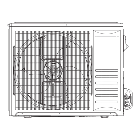
Page 11: Outlines And Dimensions
2. Outlines and dimensions Unit : in.(mm) SS-SVM001A-EM... - Page 12 2. Outlines and dimensions 48k/60k Unit : in.(mm) SS-SVM001A-EM...
-
Page 13: Electrical Data
3. Electrical data Power Supply Applicable voltage Indoor Unit Nominal Frequency Nominal Voltage (V) Umin (V) Umax (V) Sensitive (Hz) Current (A) Current (mA) 208/230 48K/60K 208/230 Note: 1. The above compressor data is based on 100% capacity combination of indoor units at the rated operating frequency. 2. -
Page 14: Capacities And Selection Data
4. Capacities and selection data 4.1 Capacity characteristic charts The following charts show the characteristics of outdoor unit capacity, which corresponds with the operating ambient temperature of outdoor unit. Conditions: ① Pipe length / height difference: 25 ft. (7.6m) / 0 ft. (0m) ②... - Page 15 3. Electrical data Performance data (Cooling operation at rated frequency) 36K outdoor unit matches 30K indoor unit Outdoor IWB (ÏF/ºC) 59/15 63/17.2 67/19.4 71/21.6 Airflow (CMF) IDB (ÏF/ºC) (ÏF/ºC) 21.1 23.9 26.7 29.4 21.1 23.9 26.7 29.4 21.1 23.9 26.7 29.4 21.1 /23.9...
- Page 16 3. Electrical data Performance data (Cooling operation at rated frequency) 36K outdoor unit matches 36K indoor unit IWB (ÏF/ºC) 59/15 63/17.2 67/19.4 71/21.6 Outdoor Airflow (CMF) IDB (ÏF/ºC) (ÏF/ºC) 21.1 23.9 26.7 29.4 21.1 23.9 26.7 29.4 21.1 23.9 26.7 29.4 21.1 23.9...
- Page 17 3. Electrical data Performance data (Cooling operation at rated frequency) 48K outdoor unit matches 42K indoor unit IWB (ÏF/ºC) 59/15 63/17.2 67/19.4 71/21.6 Outdoor Airflow (CMF) IDB (ÏF/ºC) (ÏF/ºC) 21.1 23.9 26.7 29.4 21.1 23.9 26.7 29.4 21.1 23.9 26.7 29.4 21.1 23.9...
- Page 18 3. Electrical data Performance data (Cooling operation at rated frequency) 48K outdoor unit matches 48K indoor unit Outdoor IWB (ÏF/ºC) 59/15 63/17.2 67/19.4 71/21.6 Airflow (CMF) IDB (ÏF/ºC) (ÏF/ºC) 21.1 23.9 26.7 29.4 21.1 23.9 26.7 29.4 21.1 23.9 26.7 29.4 21.1 23.9...
- Page 19 3. Electrical data Performance data (Cooling operation at rated frequency) 60K outdoor unit matches 48K indoor unit Outdoor IWB (ÏF/ºC) 59/15 63/17.2 67/19.4 71/21.6 Airflow (CMF) IDB (ÏF/ºC) (ÏF/ºC) 21.1 23.9 26.7 29.4 21.1 23.9 26.7 29.4 21.1 23.9 26.7 29.4 21.1 23.9...
- Page 20 3. Electrical data Performance data (Cooling operation at rated frequency) 60K outdoor unit matches 60K indoor unit IWB (ÏF/ºC) 59/15 63/17.2 67/19.4 71/21.6 Outdoor Airflow (CMF) IDB (ÏF/ºC) (ÏF/ºC) 21.1 23.9 26.7 29.4 21.1 23.9 26.7 29.4 21.1 23.9 26.7 29.4 21.1 23.9...
-
Page 21: Piping Length Correction Factor
3. Electrical data 4.2 Piping length correction factor The correction factor is based on the equivalent piping length in meters (EL) and the height difference between outdoor and indoor units in meters (H). Height difference between indoor unit and outdoor unit (m). •... -
Page 22: Sound Pressure Data
5. Sound pressure data Outdoor Model Model Test condition Test condition ● Model Test condition SS-SVM001A-EM... -
Page 23: Refrigerant Cycle
6. Refrigerant cycle Outdoor unit List of components Liquid SS-SVM001A-EM... - Page 24 6. Refrigerant cycle 48K/60K List of components Liquid SS-SVM001A-EM...
-
Page 25: Wiring Diagram
7. Wiring diagram 7.1 Electrical wiring diagram ectric wiring d DIP Switch Setting of Outdoor Unit SS-SVM001A-EM... - Page 26 7. Wiring diagram 48K/60K 2248372 B SS-SVM001A-EM...
-
Page 27: Control Board Picture
7. Wiring diagram 7.2 Control board picture Main control board 4 56 7 Description Description Compressor AC Power Lin DC Fan AC Power Nin Coil Temperature Sensor Reactor L2 Ambient Temperature Sensor Reactor L1 Discharge Temperature Sensor Rectifier Bridge Overheat Protector IGBT Diode Computer/Checker... - Page 28 7. Wiring diagram 7-Segment display board Description Description Computer/Checker to Outdoor Control S3-Decrease Button Board 7-Segment Display S2-Select Button DIP Switch S1-Increase Button SS-SVM001A-EM...
- Page 29 7. Wiring diagram 48K/60K Main control board Description Description DC Fan Driver1 High Pressure Switch DC Fan Driver2 Checker IPM-SI EEPROM Coil Temperature Sensor PTC Control Signal Pressure Sensor SI Signal Discharge Temperature Sensor Communication Signal Ambient Temperature Sensor AC Power SS-SVM001A-EM...
- Page 30 7. Wiring diagram Drive board Description Description DC Fan Signal Reactor L2 DC Fan Signal Compressor U IPM-SI Compressor V EEPROM Compressor W DC Fan 1 DC Fan 2 Reactor L1 SS-SVM001A-EM...
- Page 31 7. Wiring diagram Drive board Description Description N Out PTC Control Signal L Out SS-SVM001A-EM...
-
Page 32: Control Board Picture
7. Wiring diagram 7.2 Control board picture Model Power Source Transmitting Fuse or Circuit Power Supply Nominal (Btu/h) Rated Current Cable Size Cable Size Breaker (A) Sensitive Current (mA) 208/230V 3×10AWG 3×16AWG ~/60Hz 208/230V 48K / 60K 3×8AWG 3×16AWG ~/60Hz Max. -
Page 33: Filed Setting
8. Filed setting 8.1 Outdoor unit DIP switch DIP Switch Setting of Outdoor Unit (Optional setting) 1. Turn on all power sources before setting. Without turning on, the switches settings are not refreshed and might be invalid. (36K) 2. Turn off all power sources before setting. Without turning off, the switches settings are not refreshed and might be invalid.(48K/60K) ▪... - Page 34 8. Filed setting Step 4: Open the maintenance panel. Step 5: Switch the dial code (referring to outdoor wiring diagram ) ON position on the main control board. Step 6: Switch on the machine power. Step 7: Check if “40” is displayed on the LED digital tube of the main control board. Step 8: When the numerals on the LED digital tube of outdoor unit count down to 0 (40 ➝...
-
Page 35: Running Parameter Check
8. Filed setting 8.2 Running parameter check Query by 7 segment display 7-segment display Introduction ● ● ● Decrease Select Increase There are 3 buttons on the digital display board: 1) Select button: Select to display outdoor/indoor unit parameter. “ P . ” -- Parameter of outdoor unit 2) INCREASE button: Each time it is pressed, the number rises by 1. - Page 36 8. Filed setting Parameters can be checked in the following table below. Parameter Descriptions code P .0 Fault codes P .1 Compressor actual frequency P .2 Compressor driving frequency P .4 Compressor target frequency P .5 Compressor exhaust temperature P .6 Outdoor suction temperature P .7 Outdoor ambient temperature...
- Page 37 8. Filed setting 48K/60K ● ● ● Decrease Select Increase There are 3 buttons on the digital display board: 1. SWITCH button: Indoor parameters and outdoor parameters can be selected in turn by pressing it. “P . ” /“H. ” - outdoor unit parameter 2.
-
Page 38: Piping Work And Refrigerant Charg
9. Piping work and refrigerant charge 9.1 MAX. length allowed Add. Max. Height Max. Pipe Refrigerant Model difference length (L) [exceed 25ft 7.6m] 0.38(oz/ft) 131ft. (40m) 98ft. (30m) [35(g/m)] 0.38(oz/ft) 48K/60K 164ft. (50m) 98ft. (30m) [35(g/m)] 9.2 Oil trap When the indoor unit is lower than outdoor unit and height difference is larger than 16.4ft.(5m), set an oil trap every 16.4ft.(5m) (height difference) on suction piping. -
Page 39: Air Tight Test
9. Piping work and refrigerant charge 9.3 Air tight test Do use nitrogen when performing air-tight test. Connect the gauge manifold using charging hoses with a nitrogen cylinder to the check joints of the liquid line and the gas line stop valves. Perform the air-tight test. Don’t open the gas line stop valves. -
Page 40: Installation Tools And Installation Flow Chart
10. Installation tools and installation flow chart 10.1 Necessary tools and instrument list for installation Necessary Tools and Instrument List for Installation Tool Tool Tool Tool Copper Pipe Handsaw Spanner Leveler Bender Clamper for Phillips Manual Water Charging Cylinder Solderless Screwdriver Pump Terminals... - Page 41 10. Installation tools and installation flow chart Use tools and measuring instruments only for the new refrigerant which is direct contact with to refrigerant. ✧ : Interchangeability is available with R410A ●: Only for Refrigerant R32 ✕ : ✦ : Only for Refrigerant R22 Prohibited Measuring Instrument and Reason of Non-Interchangeability and...
-
Page 42: Installation Flow Chart
10. Installation tools and installation flow chart 10.2 Installation flow chart Note: This flow is only for reference; for details please see installation manual section. SS-SVM001A-EM... -
Page 43: Control Mode
11. Control mode Control function 1. Cooling Anti-Freeze Protection The outdoor pressure sensor functions as real time temperature detector of evaporator. It prevents the indoor unit evaporator temperature becoming too low. If the indoor coil temperature is too low, the compressor will automatically start protection mode. 2. -
Page 44: Sensor Parameter
12. Sensor parameter 1. THE PARAMETER OF OUTDOOR COMPRESSOR DISCHARGE TEMPERATURE SENSOR: =187.25K±6.3%: R =3.77K±2.5K: B0/100=3979K±1%) DR: Deviation Rate DR(MIN)%= (Rmin-Rnom) / Rnom*100% DR(MAX)%= (Rmax-Rnom) / Rnom*100% T [ ºC ] Rmin [ KΩ ] Rnom [ KΩ ] Rmax [ KΩ ] DR(MIN)% DR(MAX)% 908.2603... - Page 45 11. Control mode T [ ºC ] Rmin [ KΩ ] Rnom [ KΩ ] Rmax [ KΩ ] DR(MIN)% DR(MAX)% 71.2227 75.3122 79.3848 -5.43 5.13 68.1036 71.9808 75.8414 -5.39 5.09 65.1373 68.8141 72.4746 -5.34 5.05 62.3155 65.8032 69.2746 -5.30 5.01 59.6306 62.9395...
- Page 46 11. Control mode T [ ºC ] Rmin [ KΩ ] Rnom [ KΩ ] Rmax [ KΩ ] DR(MIN)% DR(MAX)% 8.0951 8.3705 8.6440 -3.29 3.16 7.8290 8.0926 8.3544 -3.26 3.13 7.5730 7.8252 8.0758 -3.22 3.10 7.3264 7.5679 7.8078 -3.19 3.07 7.0891 7.3202...
- Page 47 11. Control mode 2. THE PARAMETER OF THE OTHER SENSOR: (R =15K±2%;B0/100=3450K±2%) DR: Deviation Rate DR(MIN)%= (Rmin-Rnom) / Rnom*100% DR(MAX)%= (Rmax-Rnom) / Rnom*100% T [ºC] Rmin [ KΩ ] Rnom [ KΩ ] Rmax [ KΩ ] DR(MIN)% DR(MAX)% 60.78 64.77 68.99 -6.16...
- Page 48 11. Control mode T [ºC] Rmin [ KΩ ] Rnom [ KΩ ] Rmax [ KΩ ] DR(MIN)% DR(MAX)% 5667 5882 6103 -3.66 3.62 5449 5664 5886 -3.80 3.77 5240 5456 5678 -3.96 3.91 5048 5260 5478 -4.03 3.98 4864 5072 5286 -4.10...
- Page 49 11. Control mode T [ºC] Rmin [ KΩ ] Rnom [ KΩ ] Rmax [ KΩ ] DR(MIN)% DR(MAX)% 0.8570 0.9246 0.9971 -7.31 7.27 0.8316 0.8977 0.9687 -7.36 7.33 0.8071 0.8717 0.9412 -7.41 7.38 0.7834 0.8466 0.9146 -7.47 7.43 0.7604 0.8223 0.8888 -7.53...
-
Page 50: Troubleshooting
13. Troubleshooting 13.1 Trouble guide Troubleshooting for normal malfunction Troubleshooting Possible Reasons of Abnormality How to Deal With 1. Check power supply circuit; 2. Measure insulation resistance to 1. Power supply failure; ground to see if there is any 2. Trip of breaker or blow of fuse; leakage;... - Page 51 13. Troubleshooting Outdoor unit DC-Inverter unitary (Main control board upside-down) 1) Fault code displayed by LED lamps on outdoor main control board. There are 3 LED lamps on control board, LED1, LED2 and LED3. LED1 indicates the ten’s place of the fault code, LED2 indicates the unit’s place of the fault code and LED3 indicates outdoor drive control fault.
- Page 52 13. Troubleshooting 2) Display by 7 segment display board. Fault code will be displayed directly on 7 segment display board. 48K/60K Main control fault display Fault code will be displayed by 7 segment display on main control board. Drive fault code display The lamp of drive board flashing shows failure occurs.
-
Page 53: Fault Codes
13. Troubleshooting 13.2 Fault codes The following is the fault code table of outdoor units. Table 1 Outdoor fault code Fault Fault description Possible reasons for abnormality How to deal with Remarks code 1. Reconnect the outdoor 1. The outdoor ambient temperature ambient temperature sensor;... - Page 54 13. Troubleshooting Fault Fault description Possible reasons for abnormality How to deal with Remarks code 1. The wiring of the overload protector 1. Reconnect the wiring of the overload is connected loosely. protector; 2. The overload protector fails . 2. Replace the overload protector; Compressor 3.
- Page 55 13. Troubleshooting Fault Fault description Possible reasons for abnormality How to deal with Remarks code 1. The cable between the control board 1. Reconnect the cable between the and the driver board is connected control board and the driver board; IPM and loosely;...
- Page 56 13. Troubleshooting Note: Overload in cooling mode Table 2 Overload in cooling mode The root cause Corrective measure Discharge the refrigerant, and recharge The refrigerant is excessive. the refrigerant referring to the rating label. The outdoor ambient temperature is too Please use it within allowable temperature high.
- Page 57 13. Troubleshooting Table 3 Drive fault code (/36K) Fault Fault description Possible reasons for abnormality How to deal with code Inverter DC voltage overload fault 1. Power supply input is too high or 1. Check power supply; Inverter DC low voltage fault too low;...
- Page 58 13. Troubleshooting Table 4 Drive fault code (48K/60K) Fault Fault description Possible reasons for abnormality How to deal with code 1. Compressor wire is not connected 1. Check the wire of the compressor; properly; 2. Change the driver board ; 2.
- Page 59 13. Troubleshooting Fault Fault description Possible reasons for abnormality How to deal with code 1.The power supply is not stable ; 1. Check the power supply; The instantaneous power off 2.The instantaneous power failure; 2. Not fault; detection 3.Driver board fault; 3. Change the driver board. ...
-
Page 60: Checking Components
14. Checking components 14.1 Check refrigerant system TEST SYSTEM FLOW: ① ① ② ③ Check the c SS-SVM001A-EM... -
Page 61: Check Parts Unit
14. Checking components 14.2 Check parts unit 1. Outdoor unit fan motor DC motor 36K: ZWK511B51102 48K/60K: SIC-71FW-F8121-1 2. Compressor Compressor examination and repairing 36K: KTM310D85UMT 48K/60K: ATF400D64UMT Test in resistance. TOOL: Multi-meter. Test the resistance of the winding. The compressofar ils if the resistance of windin gis 0 (short circuit)or∞(open circuit). - Page 62 14. Checking components Note: 1) Don’t put a compressor on its side or turn over. 2) Please assemble the compressor in your air conditioner rapidly after removing the plugs. Don’t place the comp. in air for a long time. 3) Avoid compressor running in reverse caused by connecting electrical wire incorrectly. 4) Warning! In case AC voltage is impressed to compressor, the compressor performance will decrease because of its rotor magnetic force decreasing.
-
Page 63: Disassembly And Assembly For Compressor And Motor
15. Disassembly and assembly for compressor and motor The special tools for compressor & motor disassembly and assembly: Tool Hexagon Screwdriver Hexagon Socket Outdoor unit Important: Before disassembly and assembly, make sure that the power to the system has been disconnected and verified as voltage free. - Page 64 Outdoor unit 48K/60K Important: Before disassembly and assembly, make sure that the power to the system has been disconnected and verified as voltage free. Step Illustration Handling Instruction 1. Remove the top cover, handle and valve cover; 1. Remove external casing 2.
-
Page 65: Control Logic Description
16. Control logic description 16.1 An illustration to outdoor unit signal (1) Communication between indoor and outdoor units: The communication between the outdoor unit, thermostat and the indoor unit is achieved through 24V alternating current, as shown in figure below. The thermostat controls the signal output of Y, if Y-C is high level, the outdoor unit starts in cooling mode. -
Page 66: Evaporator Low-Temperature Protection
16. Control logic description Compressor running rules: When the unit starts up in cooling mode, the compressor starts to work, and adjust its operating frequency according to the system target pressure and the actual pressure. If the actual pressure is higher than the target pressure, the compressor frequency will rise; if the actual pressure is lower than the target pressure, the compressor frequency decreases;... -
Page 67: Condenser High-Temperature Protection
16. Control logic description 16.5 Condenser High-temperature Protection DC-Inverter outdoor unit AC will enter T3 protection if any of the following conditions is satisfied. Cooling mode: When the saturation temperature (which is got from low pressure cycling) T2 keeps lower than TE5 for 120 seconds, the compressor and outdoor fan will shut off. When T2 is higher than TE6, the compressor and outdoor fan will restart up. - Page 68 For more information, please visit trane.com or tranetechnologies.com. Trane has a policy of continuous product and product data improvement and reserves the right to change design and specifica- tions without notice. We are committed to using environmentally conscious print practices.
Need help?
Do you have a question about the 4TYK8536B1000AA and is the answer not in the manual?
Questions and answers