Advertisement
Quick Links
Advertisement

Related Manuals for EGO STX3800


Summary of Contents for EGO STX3800
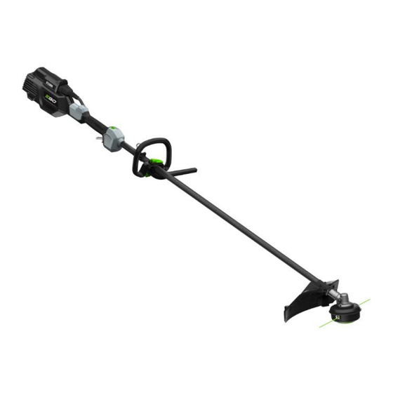
- Page 1 REPAIR GUIDELINE Line trimmer _STX3800 Version: 1 Issue Date: 01/11/2019...
- Page 2 Table of Contents Contents Page Troubleshooting Tool list Part 1: Replace the Housing Assembly and Gear Case 6-26 Part 2: Measure the Motor Assembly and PCBA 27-32 Part 3: Replace the Motor Assembly and PCBA 33-51 Part 4: Replace the Shaft and Tube Assembly 52-55...
- Page 3 Troubleshooting Fault Problem Possible Cause Test & Solution Position The motor speed varies Motor was burned due to up and down when the Motor Replace the motor overload line trimmer works. The cables that connect to Open the motor housing, check the cable motor are loose or Motor connection with motor.
- Page 4 Troubleshooting Problem Possible Cause Fault Position Test & Solution Replace the cutting line. (e.g. 2.4mm Poor cutting line Trimmer line nylon line) Not feeding line Trimmer head is broken Trimmer head Replace the trimmer head Too much dust in trimmer Trimmer head Clean the trimmer head head...
- Page 5 Tool List For Repair Tool List SPEC Remark Socket wrench 15mm Torx screwdriver T-15&T-20 Hex wrench...
- Page 6 Part 1: Replace the Housing Assembly and Gear Case...
- Page 7 1. Replace the Housing Assembly and Gear Case STX3800 LINE TRIMMER 1. Loosen 2 screws to disassemble the guard assembly, if the guard assembly is broken, replace it with a new one. Guard assembly Description Part Number Qty. Tapping screw...
- Page 8 1. Replace the Housing Assembly and Gear Case STX3800 LINE TRIMMER 2. Press the release tabs to remove the lower housing assembly & mounting wire holder ASSY. Description Part Number Qty. Mounting Wire Holder ASSY 2825610001 Lower housing assembly 2825608001...
- Page 9 1. Replace the Housing Assembly and Gear Case STX3800 LINE TRIMMER 3. Take the spring out of the upper housing assembly.
- Page 10 1. Replace the Housing Assembly and Gear Case STX3800 LINE TRIMMER 4. Rotate the upper housing assembly to align the slot in the flange with the hole in the gear case. 5. Insert the hex wrench into the aligned holes to act as a stabilizer.
- Page 11 1. Replace the Housing Assembly and Gear Case STX3800 LINE TRIMMER 6. Loosen the nut with socket wrench clockwise to remove it from the shaft.
- Page 12 1. Replace the Housing Assembly and Gear Case STX3800 LINE TRIMMER 7. Take the upper housing assembly out of the shaft. Upper housing assembly Description Part Number Qty. Upper housing 3402942001...
- Page 13 1. Replace the Housing Assembly and Gear Case STX3800 LINE TRIMMER 8. Take the flange cover out of the shaft. Flange cover Description Part Number Qty. Flange cover 3706103001...
- Page 14 1. Replace the Housing Assembly and Gear Case STX3800 LINE TRIMMER 9. Take the flange out of the shaft. Inner flange Description Part Number Qty. Inner flange 3552509001...
- Page 15 1. Replace the Housing Assembly and Gear Case STX3800 LINE TRIMMER 10. Loosen 3 screws to remove the fixing board. Washer Screw 2 Screw 1 Fixing board Description Part Number Qty. Description Part Number Qty. Screw 1 5620213003 Washer 5650598001...
- Page 16 1. Replace the Housing Assembly and Gear Case STX3800 LINE TRIMMER 11. Pull the connecting tube with one hand and pull the gear case with the other hand to separate them from each other. Description Part Number Qty. Gear case assembly...
- Page 17 1. Replace the Housing Assembly and Gear Case STX3800 LINE TRIMMER 12. With the hole in the gear case aligned with the hole in the tube, reassemble them into place. Holes...
- Page 18 1. Replace the Housing Assembly and Gear Case STX3800 LINE TRIMMER 13. Tighten the gear case with the connecting tube with screw. 14. Tighten the fixing board with the gear case with screws. Screw 2 Screw 1...
- Page 19 1. Replace the Housing Assembly and Gear Case STX3800 LINE TRIMMER 15. Mount the flange onto the shaft.
- Page 20 1. Replace the Housing Assembly and Gear Case STX3800 LINE TRIMMER 16. Mount the flange cover onto the shaft.
- Page 21 1. Replace the Housing Assembly and Gear Case STX3800 LINE TRIMMER 17. Mount the upper housing assembly onto the shaft.
- Page 22 1. Replace the Housing Assembly and Gear Case STX3800 LINE TRIMMER 18. Rotate the upper housing assembly to align the slot in the flange with the hole in the gear case. 19. Insert the hex wrench into the aligned holes to act as a stabilizer.
- Page 23 1. Replace the Housing Assembly and Gear Case STX3800 LINE TRIMMER 20. Mount the nut onto the shaft and tighten it with multifunction wrench anticlockwise. Description Part Number Qty. 5630292001...
- Page 24 1. Replace the Housing Assembly and Gear Case STX3800 LINE TRIMMER 21. Mount the spring onto the upper housing.
- Page 25 1. Replace the Housing Assembly and Gear Case STX3800 LINE TRIMMER 22. Align the release tabs on the lower housing assembly with the holes on the upper housing assembly to assemble them together. Release tab Hole...
- Page 26 1. Replace the Housing Assembly and Gear Case STX3800 LINE TRIMMER 23. Assemble the guard assembly with the fixing board with screws & washer.
- Page 27 Part 2: Measure PCBA, Motor and Internal Wire Assembly...
- Page 28 2. Measure PCBA, Motor and Internal Wire ASSY STX3800 LINE TRIMMER 1. Following the instructions for “Replacing the Motor Assembly and PCBA” to Separate the PCBA. 2. Find the capacitor in the PCBA and set the multimeter function to “Diode measuring”.
- Page 29 2. Measure PCBA, Motor and Internal Wire ASSY STX3800 LINE TRIMMER 4. Contact the red pen pin to the contact with black wire of the yellow connector (connect to the internal wire assembly) and the black pen pin to the three contactors of the black connector (connect to the motor).
- Page 30 2. Measure PCBA, Motor and Internal Wire ASSY STX3800 LINE TRIMMER 5. Contact the black pen pin to the contact (connect to the yellow line) of the black connector and red pen pin to the three contacts of the black connector (connect to the motor).
- Page 31 2. Measure PCBA, Motor and Internal Wire ASSY STX3800 LINE TRIMMER 1. Following the instructions for “Replacing the Motor Assembly and PCBA” to Separate the PCBA. 2. Set the multimeter function to “Resistance measuring”. 3. Measure the resistance between any of the two contacts.
- Page 32 2. Measure PCBA, Motor and Internal Wire ASSY STX3800 LINE TRIMMER 1. There is 6 contacts in the socket. Contact the black pen pin to the 6 contacts and the red pen pin to their corresponding contacts of the two connectors.
- Page 33 Part 3: Replacing the Motor Assembly and PCBA...
- Page 34 3. Replace the Motor Assembly and PCBA STX3800 LINE TRIMMER 1. Loosen Hexagon socket screws & 8 screws & 2 tapping screws to disassemble the housing assembly. Description Part Number Quantity Hexagon socket screw 5620019004 Screw 5620479001 Tapping screw 5610305001...
- Page 35 3. Replace the Motor Assembly and PCBA STX3800 LINE TRIMMER 2. Loosen the screw on the fixed ring. 3. Take push button, the shaft and motor out its groove. Push button Description Part Number Quantity Tapping screw 5620018005 Washer 5650598001...
- Page 36 3. Replace the Motor Assembly and PCBA STX3800 LINE TRIMMER 4. Remove the heat shrink tube and disconnect the black connector to detach the motor and PCBA. Black connector Heat shrink tube...
- Page 37 3. Replace the Motor Assembly and PCBA STX3800 LINE TRIMMER 5. Remove the two heat shrink tubes and disconnect the two connectors. Connector Heat shrink tube Connector...
- Page 38 3. Replace the Motor Assembly and PCBA STX3800 LINE TRIMMER 6. Remove all the switches as well as their cables from the handle set, replace the damaged part. Handle set Switch assembly Spring Rubber gasket Switch lever ASSY Description Part Number Spec.
- Page 39 3. Replace the Motor Assembly and PCBA STX3800 LINE TRIMMER 7. Take the PCBA away and separate the two connectors from PCBA. If PCBA is damaged, replace it with a new one. Remove heat shrink tubes Description Part Number Qty.
- Page 40 3. Replace the Motor Assembly and PCBA STX3800 LINE TRIMMER 8. Take the internal wire ASSY away. If the internal wire ASSY is damaged, replace it with a new one. Description Part Number Qty. Internal wire ASSY 4860525002...
- Page 41 3. Replace the Motor Assembly and PCBA STX3800 LINE TRIMMER 9. Align the wires into its groove and mount the PCBA into the housing. PCBA...
- Page 42 3. Replace the Motor Assembly and PCBA STX3800 LINE TRIMMER 10. Connect the two connectors(yellow in picture) . Then align them into groove. Covered with heat shrink tube...
- Page 43 3. Replace the Motor Assembly and PCBA STX3800 LINE TRIMMER 11. Loosen 3 screws to separate the motor from the shaft assembly. Motor Description Part Number Qty. Tapping screw 5620018005 Motor 2730271001...
- Page 44 3. Replace the Motor Assembly and PCBA STX3800 LINE TRIMMER 12. Replace the motor with a new one and then assemble the motor with the gear case assembly with screws.
- Page 45 3. Replace the Motor Assembly and PCBA STX3800 LINE TRIMMER 13. Replace the gear case assembly with a new one and assemble the gear case assembly with the shaft assembly with screw.
- Page 46 3. Replace the Motor Assembly and PCBA STX3800 LINE TRIMMER 14. Assemble the handle set and align the wires.
- Page 47 3. Replace the Motor Assembly and PCBA STX3800 LINE TRIMMER 15. Connect the three connector and cover them with heat shrink tube, put the shaft with motor into the housing.
- Page 48 3. Replace the Motor Assembly and PCBA STX3800 LINE TRIMMER 16. Tighten the 2 screws to fix the tube on the housing and handle set, assemble the switch lever assembly and push button on the handle set.
- Page 49 3. Replace the Motor Assembly and PCBA STX3800 LINE TRIMMER 17. Assemble the housing assembly with 17 screws. Then assemble the Rear Cover with 4 screws.
- Page 50 Part 4: Replacing the Shaft Assembly...
- Page 51 4. Replace the Shaft and Tube Assembly STX3800 LINE TRIMMER 1. Loosen the screw to separate the motor & base assembly from the shaft. Description Part Number Qty. Screw 5620213003...
- Page 52 4. Replace the Shaft and Tube Assembly STX3800 LINE TRIMMER 2. Remove the screw and take retaining ring from the shaft . Description Part Number Qty. Screw 5620213003 Retaining ring 3128598001...
- Page 53 4. Replace the Shaft and Tube Assembly STX3800 LINE TRIMMER 3. Loosen the five screws to separate cutting unit fixing board & guard from the shaft. Cutting unit Fixing board...
- Page 54 4. Replace the Shaft and Tube Assembly STX3800 LINE TRIMMER 4. Pull out the shaft from the tube ASSY and replace the shaft or the tube ASSY with a new one. Holding ring Motor with base assembly Shaft Fixed ring...
- Page 55 4. Replace the Shaft and Tube Assembly STX3800 LINE TRIMMER 5. Insert the shaft into the tube ASSY, then assemble the cutting unit, fixing board, tubing clip set, fixing ring, gear case, housing assembly and handle lever set with mounting ASSY in sequence .
Need help?
Do you have a question about the STX3800 and is the answer not in the manual?
Questions and answers