Advertisement
Quick Links
INSTRUCTION MANUAL
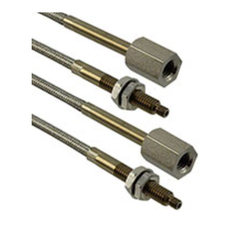
Vacuum-resistant
FT-H30-M1V, FD-H30-KZ1V, FD-H30-L32V
MJE-FV No.0101-93V
1
OUTLINE
● The vacuum-resistant fiber enables detection of sensed objects directly within a vacuum chamber, where the photo-termi-
nal FV-BR1 isolates the atmospheric side from the vacuum side.
● The simple construction and easy set up facilitates usage as do all our fiber cables.
Fiber sensor amplifier
(Red LED type)
Fiber attachment
FX-AT3 (Accsessory)
Atmospheric side fiber cables
FT-J8 (2 pcs./set)
Photo-terminals
FV-BR1 (2 pcs./set)
<Attached accessory> (The model Nos. having suffix "-S" are set model No. with accessories.)
Model No.
FV-BR1 (2 pcs./set)
FT-J8 (2 pcs./set)
FT-H30-M1V-S
○
○
FD-H30-L32V-S
○
○
FD-H30-KZ1V-S
○
○
2
CONFIGURATION
Vacuum chamber
Vacuum-resistant fiber
Photo-terminals
* Leakage: 1.33×10
-10
Pa·m
3
/s [He] or less
Thank you very much for purchasing Panasonic prod-
ucts. Read this Instruction Manual carefully and thor-
oughly for the correct and optimum use of this product.
Kindly keep this manual in a convenient place for quick
reference.
Vacuum-resistant fiber
FT-H30-M1V
FD-H30-KZ1V
Sensing object
FD-H30-L32V
Vacuum chamber
FX-AT3
FX-CT2
Mounting bracket
(Fiber attachment)
(Fiber cutter)
○
○
○
○
○
○
Atmosphere
Atmospheric side fiber cables
Chamber wall or frange
3
CAUTIONS
● This product has been developed / produced for in-
dustrial use only.
● When installing this product, take care that oil from
palms etc. is not transferred to the product.
● Since the fiber is made of glass, if it is used at places
having intense vibration or impact, or pulled exces-
sive force, the fiber may break. Take sufficient care
when using the fiber.
● The bending radius should be R18mm (R25 mm for
FT-J8) or more. If the fiber is to be mounted on a
movable part, the bending radius should be R20 mm
or more. Take care if the bending radius is less than
R25 mm, the fiber may break. However, FT-J8 can
not be mounted on a movable part.
● Keep the sensing surface and the cable joint intact.
If they are scratched, the detectability deteriorates.
● In case the sensing surface or cable joint gets dirty,
clean it with a soft cloth soaked with water.
Do not use organic solvent.
● Do not use the fiber at places where organic solvent
is contained in the air.
● Take care that the sensor is not directly exposed to
fluorescent light from a rapid starter-lamp, a high fre-
quency lighting device or sunlight, as it may affect the
sensing performance.
● Do not move or bend the fiber cable after the sensitiv-
ity was set. The sensing may become unstable.
● The upper limit operating temperature and the upper
limit storage temperature for operating or storing this
product in a high humidity environment are both
specified to be +40 °C (No dew condensation or icing
allowed).When storing this product, it is recommend-
ed that appropriate measures against humidity be
taken by the user.
4
MOUNTING
For the plate thickness of the vacuum chamber wall
(chamber or flange), refer to the recommended dimen-
-
sions shown below.
-
○
Recommended plate thickness: 3.0 mm to 20.0 mm
If a vacuum chamber whose wall thickness is outside the
recommended range is used, this product may not be in-
stalled. Check the vacuum chamber in advance.
1. Make two holes on the
vacuum tank wall (cham-
ber wall or flange). The
hole diameter must be
ø5.5 mm to ø6 mm.
2. Mount the photo-terminal FV-BR1 on the vacuum
tank wall. When mounting FV-BR1 on the wall, be
sure to mount the attached o-ring, and the side where
the o-ring is mounted should be the atomospheric
side. The tightening torque should be 0.58 N·m or
less.
O-ring
3. Mount the FT-J8 atmospheric side fibers on the atmo-
spheric side of the photo-terminal FV-BR1.
The tightening torque should be 0.58 N·m or less.
Correct
Note: The fixing nuts must be tightened securely. If not, the sensing range may
decrease.
4. Mount the vacuum-resistant fiber on the vacuum side
of the photo-terminals FV-BR1. The tightening torque
should be 0.58 N·m or less.
Correct
Note: The fixing nuts must be tightened securely. If not, the sensing range may
decrease.
5. Fix the fiber head of the vacuum-resistant fiber.
FT-H30-M1V
• T h e t i g h t e n i n g t o r q u e
should be 0.98 N·m or
less.
FD-H30-KZ1V
<If using the mounting bracket>
• Use M3 set-screws (cup
point) and the tightening
torque should be 0.05 N·m
or less.
• The fiber head can be
f i x e d e v e n w i t h o u t s e t -
screws if the mounting
bracket is fit to the body.
<If not using the mounting bracket>
• Use M3 set-screws (cup
point). The fiber should be
fixed within 15 mm from
t h e f i b e r h e a d t i p , a s
shown in the right figure.
T h e t i g h t e n i n g t o r q u e
Chamber wall
should be 0.3 N·m or less.
or flange
FD-H30-L32V
Holes
• Use M3 screws (engagement length: 3 mm or more)
ø5.5 mm to ø6 mm
and the tightening torque should be 2 N·m or less.
M3 pan-head screw
(Please arrange separately)
Panasonic Industry Co., Ltd.
1006, Oaza Kadoma, Kadoma-shi, Osaka 571-8506, Japan
https://industry.panasonic.com/
Please visit our website for inquiries and about our sales network.
Panasonic Industry Co., Ltd. 2024
O-ring
April, 2024
Clearance
Incorrect
Clearance
Incorrect
M3 set screw
(Cup point)
Mounting
bracket
M3 set screw
(Cup point)
15 mm
Tightening allow-
able area
PRINTED IN JAPAN
Advertisement

Related Manuals for Panasonic FT-H30-M1V


Summary of Contents for Panasonic FT-H30-M1V
- Page 1 3. Mount the FT-J8 atmospheric side fibers on the atmo- Thank you very much for purchasing Panasonic prod- CAUTIONS ucts. Read this Instruction Manual carefully and thor- spheric side of the photo-terminal FV-BR1. INSTRUCTION MANUAL oughly for the correct and optimum use of this product.
- Page 2 • M3ねじ(かみ合い長さ3 mm以上)を使用し、締め付 けトルクは2 N・m以下としてください。 2. 光導入端子FV-BR1を真空槽壁に取り付けます。 M3ナベねじ FV-BR1を真空槽壁に取り付ける際、必ず付属のOリ (別途ご用意ください) ングを装着し、Oリングを装着した側を大気側にな るようにしてください。 締め付けトルクは、0.58 N・m以下としてください。 真空側ファイバ 大気側ファイバ チャンバまたはフランジ 光導入端子 パナソニック インダストリー株式会社 Pa・m /s[He]以下 ※リーク量:1.33×10 〒571-8506 大阪府門真市大字門真1006番地 https://industry.panasonic.com/ Oリング Oリング <FAデバイス技術相談窓口> TEL:0120-394-205 受付時間:平日の9時~12時、13時~17時 (土日祝日、年末年始、当社休業日を除く) Panasonic Industry Co., Ltd. 2024 2024年4月発行 PRINTED IN JAPAN...
Need help?
Do you have a question about the FT-H30-M1V and is the answer not in the manual?
Questions and answers