Advertisement
Quick Links
APPLICATION, ASSEMBLY AND OPERATION MANUAL
MODELS PA6X, PA8X, PA9X, PA12
R
F
, E
ISK OF
IRE
LECTRIC
I
. O
NJURY
BSERVE ALL
C
FOLLOWING
AUTIONS
1. Before servicing or cleaning the unit, switch power
off at disconnect switch or service panel and lock-
out/tag-out to prevent power from being switched
on accidentally. More than one disconnect switch
may be required to de-energize the equipment for
servicing.
2. This installation manual shows the suggested
installation method. Additional measures may be
required by local codes and standards.
3. Installation work and electrical wiring must be done
by qualified professional(s) in accordance with all
applicable codes, standards and licensing
requirements.
4. Any structural alterations necessary for installation
must comply with all applicable building, health,
and safety code requirements.
5. Electrical equipment connected to this unit must be
properly grounded.
6. Sufficient air is needed for proper combustion and
PA_Manual_AUG09 138239_003
S
,
HOCK
OR
C
ODES AND THE
!
Due to continuing product development, specifications are subject to change without notice.
www.renewaire.com
exhausting of gases through the flue (chimney)
of fuel burning equipment that might be
installed in the area affected by this equipment.
If this unit is exhausting air from a space in
which chimney-vented fuel burning equipment
is located, take steps to assure that combustion
air supply is not affected. Follow the heating
equipment manufacturer's requirements and
the combustion air supply requirements of
applicable codes and standards.
7. Use the unit only in the manner intended by the
manufacturer. If you have questions, contact
the manufacturer.
8. This unit is intended for general ventilating only.
Do not use to exhaust hazardous or explosive
materials and vapors. Do not connect this unit
to range hoods, fume hoods or collection
systems for toxics.
9. This unit must be properly ducted to the
outdoors. Outside air inlets must not be
located where air may be contaminated, for
example by vehicle or appliance exhausts.
10. Use the unit only in the manner intended by the
manufacturer. If you have questions, contact
the manufacturer at 800-627-4499.
Revised 8/09
4510 Helgesen Drive, Madison, WI, 53718
608.221.4499, 800.627.4499, Fax: 608.221.2824
support@renewaire.com www.renewaire.com
Covered by
US Patent
5,660,228
¤
2009 RenewAire LLC
Advertisement

Subscribe to Our Youtube Channel
Related Manuals for RenewAire PA6X


Summary of Contents for RenewAire PA6X
- Page 1 4510 Helgesen Drive, Madison, WI, 53718 608.221.4499, 800.627.4499, Fax: 608.221.2824 support@renewaire.com www.renewaire.com APPLICATION, ASSEMBLY AND OPERATION MANUAL MODELS PA6X, PA8X, PA9X, PA12 Covered by US Patent 5,660,228 exhausting of gases through the flue (chimney) of fuel burning equipment that might be...
- Page 2 See table below: OWNER’S INFORMATION Two-stack Three-stack Three-high PA6X PA9X OPERATION ······································ 31 Four-high PA8X PA12X MAINTENANCE ································· 32 Due to continuing product development, specifications are subject to change without notice. ¤ PA_Manual_AUG09 138239_003 www.renewaire.com Revised 8/09 2009 RenewAire LLC...
- Page 3 DIMENSIONS Due to continuing product development, specifications are subject to change without notice. ¤ PA_Manual_AUG09 138239_003 www.renewaire.com Revised 8/09 2009 RenewAire LLC...
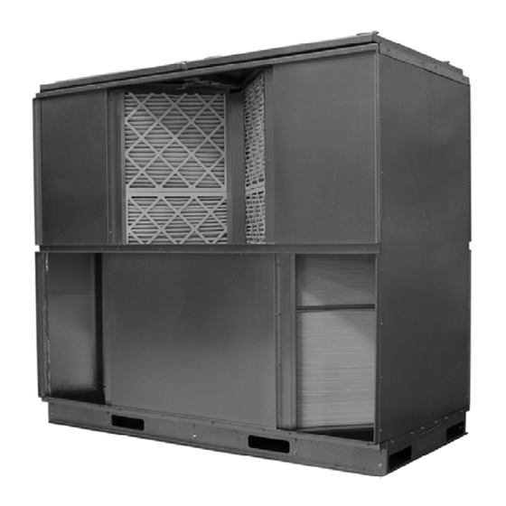
- Page 4 SYSTEM DESIGN – GENERAL SPECIAL CONSIDERATIONS FOR FUNCTION OUTSIDE AIR AND EXHAUST AIR The patented RenewAire PA6X, PA8X, PA9X and PA12X modular energy-recovery units are used to DUCTS transfer energy from exhaust air leaving a building, Proper location and construction of these ducts are...
- Page 5 DIFFERENTIALS”, page 7. FIGURE B – PULL-PULL BLOWER LAYOUT RECOMMENDED FIGURE D – RA PUSH – FA PULL LAYOUT NOT RECOMMENDED Due to continuing product development, specifications are subject to change without notice. ¤ PA_Manual_AUG09 138239_003 www.renewaire.com Revised 8/09 2009 RenewAire LLC...
- Page 6 15°. unit should not exceed 4 inches (H FIGURE E – PRESSURE DROP THROUGH PA-SERIES UNITS Due to continuing product development, specifications are subject to change without notice. ¤ PA_Manual_AUG09 138239_003 www.renewaire.com Revised 8/09 2009 RenewAire LLC...
- Page 7 Thus the leakage volumes presented here are both easier to apply and more accurate when considering the entire system. Due to continuing product development, specifications are subject to change without notice. ¤ PA_Manual_AUG09 138239_003 www.renewaire.com Revised 8/09 2009 RenewAire LLC...
- Page 8 FIGURE 1 – ARRANGEMENTS 1 & 3 (OPPOSITE-SIDE ENTRIES) job. Remember that the filters must be installed to cover the inlet faces of the core stacks. Due to continuing product development, specifications are subject to change without notice. ¤ PA_Manual_AUG09 138239_003 www.renewaire.com Revised 8/09 2009 RenewAire LLC...
- Page 9 2 percentage points. Reduce total effectiveness by 1 percentage point. FIGURE 2 – ARRANGEMENTS 2 & 4 (SAME-SIDE ENTRIES) Due to continuing product development, specifications are subject to change without notice. ¤ PA_Manual_AUG09 138239_003 www.renewaire.com Revised 8/09 2009 RenewAire LLC...
- Page 10 Nut Driver ¼” Nut Driver ” #2 Phillips Driver 1/8” Drill Bit Tape Measure 1/8” Allen Wrench Caulk Gun Rubber Mallet Due to continuing product development, specifications are subject to change without notice. ¤ PA_Manual_AUG09 138239_003 www.renewaire.com Revised 8/09 2009 RenewAire LLC...
- Page 11 Base 101048 Filter Rack End 101062 Filter Rack End 101046 U-Duct Flange FASTENERS PROVIDED WITH UNIT (SHOWN ACTUAL SIZE) Due to continuing product development, specifications are subject to change without notice. ¤ PA_Manual_AUG09 138239_003 www.renewaire.com Revised 8/09 2009 RenewAire LLC...
- Page 12 (Fig. 5). Core Center Spacers come with (2) S-slips FIGURE 4 – CHECK CORE PLACEMENT. installed. Insert flange of RenewAire ENERGY RECOVERY CORE into S-slip on Core Center Spacer (Fig. 7). FIGURE 7 – DETAIL OF CORE CENTER SPACER BETWEEN TWO CORE STACKS.
- Page 13 Place 3 Core. Check locations of the stacks (Fig. 11). FIGURE 11 – ENERGY-RECOVERY CORE LOCATIONS FOR THREE-STACK UNIT. Due to continuing product development, specifications are subject to change without notice. ¤ PA_Manual_AUG09 138239_003 www.renewaire.com Revised 8/09 2009 RenewAire LLC...
- Page 14 FIGURE 12 – CONTINUE FIRST CORE STACK. FIGURE 13 – CONTINUE SECOND CORE STACK. FIGURE 14 – SECOND CORE STACK COMPLETED. Due to continuing product development, specifications are subject to change without notice. ¤ PA_Manual_AUG09 138239_003 www.renewaire.com Revised 8/09 2009 RenewAire LLC...
- Page 15 ASSEMBLY: Install End Panels Place S-Slips on the RenewAire Core Flanges at both ends of the Array, so the END PANELS can be installed (Fig 15). FIGURE 15 – PLACE S-SLIPS ON END FLANGES. Install END PANELS. Bottom edges of END PANELS go inside the BASE.
- Page 16 CONNECTING THE CORES TO THE END PANELS AND CENTER SPACERS! FIGURE 19 – CORE STACKS AND END PANELS MUST BE PLUMB AND LEVEL. Due to continuing product development, specifications are subject to change without notice. ¤ PA_Manual_AUG09 138239_003 www.renewaire.com Revised 8/09 2009 RenewAire LLC...
- Page 17 FIGURE 21 – PARTS OF TWIN FILTER RACKS, VIEWED FROM ABOVE. FIGURE 23 – ASSEMBLE TWIN FILTER RACKS. FIGURE 22 – DETAIL OF TWIN FILTER RACK. Due to continuing product development, specifications are subject to change without notice. ¤ PA_Manual_AUG09 138239_003 www.renewaire.com Revised 8/09 2009 RenewAire LLC...
- Page 18 The flanges on the FILTER RACKS should be up very close to the S-slips on the CORE STACKS (Fig. 27, next page). PA6X AND PA8X – ARRANGEMENT 2 & 4 ONLY: Attach Flanges to each of the remaining Single Filter Racks before installing them.
- Page 19 RACKS with the S-SLIPS on the CORE STACKS (Fig. 27). FIGURE 27 – ALIGNMENT OF FILTER RACK FLANGES AND CORE STACKS. Due to continuing product development, specifications are subject to change without notice. ¤ PA_Manual_AUG09 138239_003 www.renewaire.com Revised 8/09 2009 RenewAire LLC...
- Page 20 FIGURE 29 – FILTER RACK AND SIDE PANEL. CAUTION Do not install any screws at this time! FIGURE 30 – PLACE SECOND SIDE PANEL. Due to continuing product development, specifications are subject to change without notice. ¤ PA_Manual_AUG09 138239_003 www.renewaire.com Revised 8/09 2009 RenewAire LLC...
- Page 21 Complete placing all the SIDE PANELS (Fig. 32). FIGURE 32 – ALL SIDE PANELS INSTALLED (TWO- STACK UNIT SHOWN). Due to continuing product development, specifications are subject to change without notice. ¤ PA_Manual_AUG09 138239_003 www.renewaire.com Revised 8/09 2009 RenewAire LLC...
- Page 22 FILTER RACKS and the SIDE PANELS (Fig. 34). FIGURE 34 – INTERSECTION OF CORE STACKS, FILTER RACKS AND TOP DUCT FLANGE. Due to continuing product development, specifications are subject to change without notice. ¤ PA_Manual_AUG09 138239_003 www.renewaire.com Revised 8/09 2009 RenewAire LLC...
- Page 23 PANELS. FIGURE 36 – END CROSS BAR IN POSITION. FIGURE 37 – SCREW END CROSS BAR ONTO END PANELS. Due to continuing product development, specifications are subject to change without notice. ¤ PA_Manual_AUG09 138239_003 www.renewaire.com Revised 8/09 2009 RenewAire LLC...
- Page 24 Put U-DUCT FLANGE in position (Fig. 40). It should fit snugly between the SIDE DUCT FLANGES. FIGURE 40 – INSTALL U-DUCT FLANGE. Due to continuing product development, specifications are subject to change without notice. ¤ PA_Manual_AUG09 138239_003 www.renewaire.com Revised 8/09 2009 RenewAire LLC...
- Page 25 DUCT FLANGE. Attach each L-DUCT FLANGE. Use #12 screws. Drill 1/8” pilot holes. FIGURE 42 – ATTACH SIDE DUCT FLANGES. Due to continuing product development, specifications are subject to change without notice. ¤ PA_Manual_AUG09 138239_003 www.renewaire.com Revised 8/09 2009 RenewAire LLC...
- Page 26 FIGURE 43 – CHECK LONG TOP BAR SPACING. FIGURE 44 – CENTER TOP CROSS BAR BETWEEN CORE STACKS. FIGURE 45 – INSTALL TOP CROSS BAR. Due to continuing product development, specifications are subject to change without notice. ¤ PA_Manual_AUG09 138239_003 www.renewaire.com Revised 8/09 2009 RenewAire LLC...
- Page 27 Caulk all accessible joints to prevent air leakage between compartments. FIGURE 48 – DRIVE SCREWS INTO EDGE OF SIDE PANELS. Due to continuing product development, specifications are subject to change without notice. ¤ PA_Manual_AUG09 138239_003 www.renewaire.com Revised 8/09 2009 RenewAire LLC...
- Page 28 (Fig. 53). FIGURE 51 – CORRECT ORIENTATION OF LATCHES. FIGURE 52 – SECURE LATCHES. FIGURE 53 – LATCH DETAIL. Due to continuing product development, specifications are subject to change without notice. ¤ PA_Manual_AUG09 138239_003 www.renewaire.com Revised 8/09 2009 RenewAire LLC...
- Page 29 Due to continuing product development, specifications are subject to change without notice. ¤ PA_Manual_AUG09 138239_003 www.renewaire.com Revised 8/09 2009 RenewAire LLC...
- Page 30 4. Keep unit level while moving. MINIMUM FORK LENGTHS UNIT SIDE LIFT END LIFT PA6X 40” PA8X 40” PA9X 66” PA12X Due to continuing product development, specifications are subject to change without notice. ¤ PA_Manual_AUG09 138239_003 www.renewaire.com Revised 8/09 2009 RenewAire LLC...
- Page 31 3) temperature difference between the two airstreams. See the product specification sheets to determine the expected energy exchange effectiveness under specific conditions. Due to continuing product development, specifications are subject to change without notice. ¤ PA_Manual_AUG09 138239_003 www.renewaire.com Revised 8/09 2009 RenewAire LLC...
- Page 32 Do not replace with filters rated less than MERV-6. Initial Resistance of Filters supplied with this unit: INITIAL PRESSURE DROP: 20" x 20" MERV 8 FILTERS RENEWAIRE SERVICE PART NUMBER 990083 1000 CFM/FILTER Due to continuing product development, specifications are subject to change without notice.
Need help?
Do you have a question about the PA6X and is the answer not in the manual?
Questions and answers