
Related Manuals for RenewAire PA ERV Series


Summary of Contents for RenewAire PA ERV Series
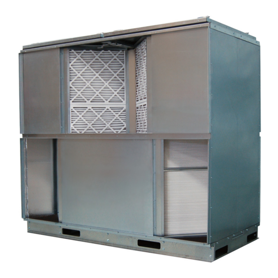
- Page 1 PA SERIES ERV Installation, Operation and Maintenance Manual PA6X PA8X PA9X PA12 PA6X shown...
- Page 2 PA-Series WARNING WARNING Danger of carbon monoxide poisoning! Outside air intake RISK OF FIRE, ELECTRIC SHOCK, OR INJURY. should be 10' (minimum) away from sources of carbon mon- oxide or other toxic gases such as chimneys, furnace, or water OBSERVE ALL CODES AND THE FOLLOWING: heater exhausts.
- Page 3 The completed Locate the RenewAire unit label found on the outside of the unit. document is to be turned NOTE: This information is for purposes of identifying the unit-specific option data from the over to the owner after Option Code.
- Page 4 PA6X Airflow (CFM) Airflow (CFM) 2000 4000 6000 8000 3000 6000 9000 12000 15000 PA8X PA12X At AHRI 1060 standard conditions. See all AHRI certifi ed ratings at www.ahrinet.org. Specifi cations may be subject to change without notice. RENEWAIRE.COM 1.800.627.4499 1.800.627.4499...
- Page 5 RENEWAIRE.COM FOR THE MOST COMPLETE AND CURRENT INFORMATION VISIT 1.800.627.4499...
- Page 6 SPECIFICATIONS & DIMENSIONS RENEWAIRE.COM 1.800.627.4499 1.800.627.4499...
- Page 7 RENEWAIRE.COM FOR THE MOST COMPLETE AND CURRENT INFORMATION VISIT 1.800.627.4499...
- Page 8 SPECIFICATIONS & DIMENSIONS RENEWAIRE.COM 1.800.627.4499 1.800.627.4499...
-
Page 9: Table Of Contents
TABLE OF CONTENTS PA-Series 1.0 OVERVIEW 3.2 CHECKING OPERATION OF THE PA-SERIES ....36 3.2.1 Airflow ................36 1.1 PA-SERIES INSTALLER INFORMATION ....11 3.2.2 Energy Exchange ..............36 3.2.3 Operating Controls............36 1.2 SYSTEM DESIGN—GENERAL ........11 3.2.4 Continuous Operation ............36 1.2.1 Function ................11 3.2.5 Operation in Extreme Cold Weather ........36 1.2.2 For Indoor Use Only ............ - Page 10 TABLE OF CONTENTS PA-Series TABLE OF ILLUSTRATIONS Figure 1.3.0 Push-Push Blower Layout—Recommended ..............13 Figure 1.3.1 Pull-Pull Blower Layout—Recommended ............... 13 Figure 1.3.2 OA Push–EA Pull Blower Layout (can be used with caution) ..........14 Figure 1.3.3 RA Push–FA Pull Blower Layout, Not Recommended ............14 Figure 1.4.0 Pressure Drop through PA-Series Units ................
-
Page 11: Overview
OVERVIEW PA-Series 1.0 OVERVIEW 1.1 PA-SERIES INSTALLER INFORMATION The PA-Series Energy Recovery Ventilators (ERVs) are available either factory-assembled or knocked-down for on-site assembly. If the unit is received pre-assembled, please be sure to: review the Forklift Information section; review the Warnings and Cautions at the front of the manual. If you are assembling the unit please be sure to: review the Warnings and Cautions at the front of the manual;... -
Page 12: Four Ducts Are Required
SYSTEM DESIGN PA-Series 1.2.7 Four Ducts are Required Outside Air Duct handles Supply Air entering the ERV. Fresh Air Duct handles Supply Air leaving the ERV. Return Air Duct handles Exhaust Air entering the ERV. Exhaust Air Duct carries the Exhaust Air from the ERV to the outside of the building. 1.2.8 Special Considerations for Outside Air and Exhaust Air Ducts Proper location and construction of these ducts are critical to the safety and proper function of the sytem. -
Page 13: Figure 1.3.0 Push-Push Blower Layout-Recommended
ERV, see Figure 1.3.1. These layouts minimize leakage between the airstreams due to pressure differences. INSULATE THESE DUCTS AND BLOWER FIGURE 1.3.0 PUSH-PUSH BLOWER LAYOUT—RECOMMENDED www.renewaire.com (800) 627- 4499 support@renewaire.com INSULATE THESE DUCTS AND BLOWER FIGURE 1.3.1 PULL-PULL BLOWER LAYOUT—RECOMMENDED www.renewaire.com... -
Page 14: Oa Push-Ea Pull Blower Layout
See section 1.5 Static Pressure Differentials on page 16. INSULATE THESE DUCTS AND BLOWERS FIGURE 1.3.2 OA PUSH–EA PULL BLOWER LAYOUT (CAN BE USED WITH CAUTIONS) www.renewaire.com (800) 627- 4499 support@renewaire.com FIGURE 1.3.3 RA PUSH–FA PULL BLOWER LAYOUT, NOT RECOMMENDED www.renewaire.com (800) 627- 4499 support@renewaire.com... -
Page 15: System Design-Blower Sizing
SYSTEM DESIGN PA-Series 1.4 SYSTEM DESIGN—BLOWER SIZING CAUTION 1.4.1 Blower Sizing Maximum Differential Pres- See Figure 1.4.0 below for pressure drop through the PA ERVs. The chart does not include sure allowances for inlet/outlet plenums, which are not included with the unit. The chart includes The maximum pressure pressure drop through clean filters. -
Page 16: System Design-Static Pressure Differential
INSTALLATION PA-Series 1.5 SYSTEM DESIGN—STATIC PRESSURE DIFFERENTIAL NOTE: The leakage volume is shown Strong static pressure differences can result in air leakage from one airstream to the other here as a function within the energy-recovery assembly. strictly of static pressure When the Average Static Pressure Difference between the two airstreams is greater than 1", differenece, not overall you may need to account for leakage airflow in your blower selection. -
Page 17: Comparison Of Leakage Volume And Eatr Ratings
INSTALLATION PA-Series 1.5.3 Comparison of Leakage Volume and EATR Ratings NOTE: Deter- mine how many Leakage volumes presented here are application ratings for the complete PA-Series energy- recovery unit. EATR is a certified rating point used in ARI’s 1060 program for the energy- “twinned filters”... -
Page 18: Figure 2.1.0 Arrangements 1 And 3 (Opposite-Side Entries)
INSTALLATION PA-Series CAUTION "ARRANGEMENT 1" Derate performance if using OPPOSITE-SIDE ENTRIES Parallel Airflow CROSS AIRFLOWS Views (Arrangements 3 and 4). Reduce sensible effectiveness by 2 percent- age points. Reduce total effectiveness by 1 percentage point. Front Views End View OPENING SIDE PANEL Back Views REQUIRES (2) -
Page 19: Figure 2.1.1 Arrangements 2 And 4 (Same-Side Entries)
INSTALLATION PA-Series CAUTION "ARRANGEMENT 2" Derate performance if using SAME-SIDE ENTRIES Parallel Airflow CROSS AIRFLOWS Views (Arrangements 3 and 4). Reduce sensible effectiveness by 2 percent- age points. Reduce total effectiveness by 1 percentage point. Front Views End View OPENING Back Views SIDE PANEL REQUIRES (1) -
Page 20: Assembly
INSTALLATION PA-Series 2.2 ASSEMBLY 2.2.1 Tools Required Cordless Driver/Drill with the following bits: Nut Driver 5/16" #2 Philips or Square Driver 1/8" Drill Bit Tape Measure 1/8" Allen Wrench Caulk Gun Rubber Mallet 2.2.2 Parts Lists PARTS LIST FOR PA-6X PARTS LIST FOR PA-8X Part Part... - Page 21 INSTALLATION PA-Series PARTS LIST FOR PA-9X PARTS LIST FOR PA-12X Part Part Quantity Description Quantity Description Number Number 100030 Door 100030 Door 100040 S-Slip 59" 135822 S-Slip 79" 104199 Filter Removal Hook 104198 Filter Removal Hook 101006 Top Cross Bar 101006 Top Cross Bar 140771 Side Duct Flange 140778 Side Duct Flange...
-
Page 22: Stack Energy Recovery Cores
Check location of the core, see Figure 2.2.2. Core should be 2-5/16" from the end and 1-1/2" DOWN. from the front of the base. Install Core Center Spacer to 1st RenewAire Energy Recovery Core. Core Center Spacers come with (2) S-slips installed. Insert flange of RenewAire ENERGY RECOVERY CORE into S-slip on Core Center Spacer, Figure 2.2.3. -
Page 23: Install End Panels
Complete the Core Stacks. Double check stack placement by measuring. 2.2.4 Install End Panels Place S-Slips on the RenewAire Core Flanges at both ends of the Array, so the End Panels can be installed, Figure 2.2.5. Install End Panels, Figure 2.2.6. -
Page 24: Figure 2.2.5 Place S-Slips On End Flanges
INSTALLATION PA-Series S-SLIP FIGURE 2.2.5 PLACE S-SLIPS ON END FLANGES www.renewaire.com (800) 627- 4499 support@renewaire.com FIGURE 2.2.6 INSTALL END PANELS www.renewaire.com (800) 627- 4499 support@renewaire.com 1.800.627.4499... -
Page 25: Square Up And Connect Cores, Center Spacer, And Ends
TOPS OF THE CORE STACKS SHOULD BE LEVEL. CORNERS SHOULD ALL BE AT THE SAME HEIGHT. 73-1/16" OR 109-1/8" OUTSIDE DIMENSION DEPENDING ON MODEL. FIGURE 2.2.7 CORE STACKS AND END PANELS MUST BE PLUMB AND LEVEL www.renewaire.com (800) 627- 4499 support@renewaire.com 1.800.627.4499... -
Page 26: Assemble Twinned Filter Rack(S)
FILTER SPACER RIGHT-HAND RACK LEFT-HAND RACK FLANGES MUST POINT AWAY FROM FILTER SPACER FIGURE 2.2.8 PARTS OF TWINNED FILTER RACKS (TOP VIEW) www.renewaire.com (800) 627- 4499 support@renewaire.com FIGURE 2.2.9 ASSEMBLE TWINNED FILTER RACKS 2.2.7 Install Filter Racks www.renewaire.com (800) 627- 4499 support@renewaire.com... -
Page 27: Figure 2.2.10 Place Twinned Filter Racks Against Energy Recovery Cores (Two-Stack Units)
Array. FIGURE 2.2.10 PLACE TWINNED FILTER RACKS AGAINST ENERGY RECOVERY CORES (TWO-STACK UNITS) (800) 627- 4499 support@renewaire.com FIGURE 2.2.11 PLACE SINGLE FILTER RACKS AGAINST APPROPRIATE CORE STACK FACES ww.renewaire.com (800) 627- 4499 support@renewaire.com... -
Page 28: Install Side Panels
FIGURE 2.2.13 PLACE LARGE SIDE PANELS Align Flanges of Filter Racks with edges of Side Panels. Flanges on Filter Racks tuck into www.renewaire.com (800) 627- 4499 support@renewaire.com the inside corner of the Side Panels that covers the compartment in which the Filter Rack is installed. -
Page 29: Install Top Duct Flange
Continue with adding the small side panels. See Figure 2.2.15. FIGURE 2.2.15 PLACE SMALL SIDE PANELS 2.2.9 Install Top Duct Flange Install Long Top Duct Flange, Figure 2.2.16. www.renewaire.com (800) 627- 4499 support@renewaire.com Attach each Top Duct Flange to Side Panels with #8 self-drilling screws. The Top Duct Flange... -
Page 30: Install End Cross Bars
FIGURE 2.2.17 INTERSECTION OF CORE STACKS, FILTER RACKS, AND TOP DUCT FLANGE 2.2.10 Install End Cross Bars Attach End Cross Bars to End Panels with (4) #8 self-drilling screws, See Figure 2.2.18. www.renewaire.com (800) 627- 4499 support@renewaire.com END CROSS BAR FIGURE 2.2.18 END CROSS BAR INSTALLATION... -
Page 31: Install Duct Flanges
Do not install any screws at this time! L-DUCT CHANNEL FIGURE 2.2.19 INSTALL L-DUCT CHANNELS www.renewaire.com (800) 627- 4499 support@renewaire.com Install (8) Side Duct Flanges next, (4) on each side, see Figure 2.2.20. Slide Side Duct Flanges into the slot in End Panels. Do not screw these in place at this time. -
Page 32: Install Top Cross Bar(S)
FIGURE 2.2.21 INSTALL U-DUCT FLANGE Once the U-Duct Flange is attached, use (4) #8 self-drilling screws on each Duct Flange to attach them to the end panels and attach each L-Duct Flange using #12 self-drilling screws. www.renewaire.com (800) 627- 4499 support@renewaire.com 2.2.12 Install Top Cross Bar(s) -
Page 33: Screw Side Panels To Core Stacks And Filter Racks
Install screws through Filter Rack Flanges or S-Slips on Core Stacks to connect all pieces together. Use #12 self-drilling screws. Drill 1/8" pilot holes. Caulk all accessible joints to prevent air leakage between compartments. FIGURE 2.2.23 LOCATIONS FOR SCREWS www.renewaire.com (800) 627- 4499 support@renewaire.com 1.800.627.4499... -
Page 34: Install Doors
Apply final caulking, Figure 2.2.25. Purpose of caulking at this stage is to prevent leakage of air from ducts. Assembly is complete! Check the following: www.renewaire.com (800) 627- 4499 support@renewaire.com Panels and filter racks are placed correctly for the airflow paths required for the job. -
Page 35: Forklift Information
OPERATION PA-Series WARNING Danger of carbon monoxide poisoning! Outside air intake should be 10' (minimum) away from sources of carbon monoxide or other toxic gases such as chimneys, furnace, or water heater exhausts. Do not locate outside air intake where vehicles may be serviced or left idling. Do not locate the outside air intake inside an enclosed space. -
Page 36: Operation
OPERATION PA-Series 3.0 OPERATION NOTE: System blowers are not 3.1 BASIC FUNCTION OF PA-SERIES ERV provided with the The PA-Series ERV transfers heating or cooling energy from an exhaust airstream to a fresh PA-Series and are provided airstream. by others. The energy-recovery cores operate with no moving parts. -
Page 37: Maintenance
MAINTENANCE PA-Series 4.0 MAINTENANCE WARNING Danger of eye injury from moving air when servicing energy exchanger! Always disconnec power source before servicing, to ensure no airflow in the system. CAUTION Maintenance procedures must be followed. System will not perform as designed unless filters are changed and the energy recovery cores are cleaned as described below. -
Page 38: Factory Assistance
To contact RenewAire Customer Service: Call 800-627-4499 RenewAireSupport@RenewAire.com Email: Remember that RenewAire Customer Service can only assist with the products sold by RenewAire, it cannot resolve engineering issues that result from air handling system design by others. 1.800.627.4499... - Page 39 PA-Series T H I S P A G E I S I N T E N T I O N A L LY L E F T B L A N K . THIS PAGE IS INTENTIONALLY LEFT BLANK 1.800.627.4499...
- Page 40 About RenewAire For over 30 years, RenewAire has been a pioneer in enhancing indoor air quality (IAQ) in commercial and residential buildings of every size.This is achieved while maximizing sustainability through our fifth-generation, static-plate, enthalpic-core Energy Recovery Ventilators (ERVs) that optimize energy efficiency, lower capital costs via load reduction and decrease operational expenses by minimizing equipment needs, resulting in significant energy savings.
Need help?
Do you have a question about the PA ERV Series and is the answer not in the manual?
Questions and answers