Table of Contents
Advertisement
Quick Links
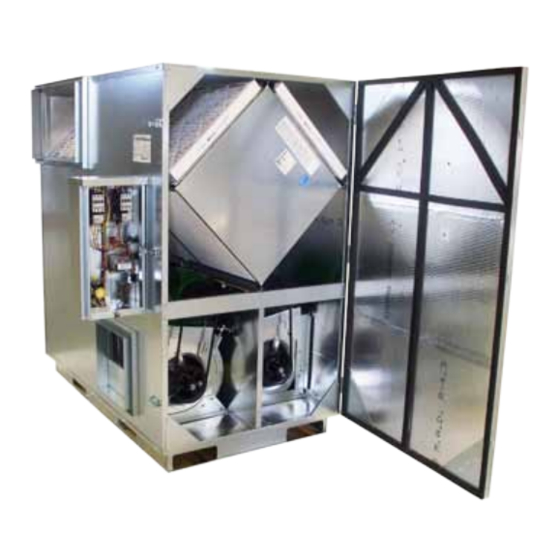
INSTALLATION AND OPERATION MANUAL
HE3XINV
NOTE: Disconnect Switch and 24V Transformer Standard
In 2012, these ERVs may be ordered with new factory-
installed features including Isolation Dampers and Variable
Frequency Drives. Consult the supplemental Installation
and Operation Manual(s) for these features if supplied.
HE3XINV
Due to continuing product development, specifications are subject to change without notice.
134772_006
HE3XINVMan_Jan12.indd
4510 Helgesen Drive, Madison, WI 53718
(608) 221-4499, (800) 627-4499, Fax: (608) 221-2824
support@renewaire.com www.renewaire.com
RISK OF FIRE, ELECTRIC SHOCK, OR INJURY.
OBSERVE ALL CODES AND THE FOLLOWING:
1. Before servicing or cleaning the unit, switch power
off at disconnect switch or service panel and lock-
out/tag-out to prevent power from being switched on
accidentally. More than one disconnect switch may be
required to de-energize the equipment for servicing.
2. This installation manual
installation method. Additional measures may be
required by local codes and standards.
3. Installation work and electrical wiring must be
done by qualified professional(s) in accordance
with all applicable codes, standards and licensing
requirements.
4. Any structural alterations necessary for installation
must comply with all applicable building, health, and
safety code requirements.
5. This unit must be grounded.
6. Sufficient air is needed for proper combustion and
exhausting of gases through the flue (chimney) of fuel
burning equipment that might be installed in the area
affected by this equipment. If this unit is exhausting
air from a space in which chimney-vented fuel
burning equipment is located, take steps to assure
that combustion air supply is not affected. Follow the
heating equipment manufacturer's requirements and
the combustion air supply requirements of applicable
codes and standards.
7. Use the unit only in the manner intended by the
manufacturer. If you have questions, contact the
manufacturer.
8. This unit is intended for general ventilating only. Do
not use to exhaust hazardous or explosive materials
and vapors. Do not connect this unit to range hoods,
fume hoods or collection systems for toxics.
9. When cutting or drilling into wall or ceiling, do not
damage electrical wiring and other hidden utilities.
10. If installed indoors this unit must be properly ducted
to the outdoors.
To avoid motor bearing damage and noisy and/or
unbalanced impellers, keep drywall spray, construction
dust, etc., out of unit.
Do not remove or disable the wiring interconnection between the
Overload Relays and the Contactors. Without this interconnection
the motor(s) will not be protected against overload.
Revised 01/2012
shows the
© 2012 RenewAire LLC
www.renewaire.com
suggested
Page 1
Advertisement
Table of Contents

Related Manuals for RenewAire HE3XINV


Summary of Contents for RenewAire HE3XINV
- Page 1 Do not remove or disable the wiring interconnection between the Overload Relays and the Contactors. Without this interconnection the motor(s) will not be protected against overload. HE3XINV Due to continuing product development, specifications are subject to change without notice. © 2012 RenewAire LLC 134772_006 HE3XINVMan_Jan12.indd Revised 01/2012 www.renewaire.com...
- Page 2 Placement of the HE3XINV Exhaust & Fresh Air Ducts Between HE3XINV & Outside The HE3XINV is designed for installation in a sheltered location, out of the weather. Insulation The preferred mounting location is sitting on a concrete floor. Ducts connecting the HE3XINV to the outside must be insulated, Unit base may be bolted to floor.
-
Page 3: Sound Attenuation
Duct Fresh Air from the HE3XIN into the heated space Fresh Air from the HE3XINV often can be ducted into an existing HVAC These guidelines are consistent with SMACNA recommended duct air distribution system. - Page 4 12" X 16" (Optional) DUCT FLANGE DUCT FLANGE RIGHT VIEW FRONT VIEW LEFT VIEW HE3XINV Product Configuration Chart 10 UNUSED IN HE-3X MODELS 1-5 MODEL: "HE-3X" 16-17 UNUSED IN HE-3X MODELS CORE: "J" = G5 RESTRICTIONS: OPTION 1: 24V TRANSFORMER 7-8 INDOOR/OUTDOOR: "IN"...
-
Page 5: Operation
Operating Controls A wide variety of control schemes may be selected by the The HE3XINV has one basic purpose: to exhaust air from a engineer, installer, or owner to meet the ventilation needs of structure and bring in fresh air from outside, while transferring the facility. -
Page 6: Measuring Airflow
Measuring Airflow HE3XINV Electrical Specifications NOTE: Proper Wiring Size Selection and Wiring Installation Equipment Required • A magnehelic gauge or other device capable of measuring 0 are the Responsibility of the Electrical Contractor. to 1.5 in. water of differential pressure. - Page 7 HE3XINV P1 Wiring Schematics with Independent Blower Control OPTIONS INSTALLED: INDEPENDENT BLOWER CONTROL MOTOR STARTER DISCONNECT FUSE SWITCH (IF INSTALLED AT FACTORY) POWER SUPPLY 1 PHASE 60Hz MOTOR SEE UNIT RATING LABEL FOR VOLTAGE, MCA (OA) AND MOPD 24VAC MOTOR...
- Page 8 HE3XINV P3 Wiring Schematics with Independent Blower Control OPTIONS INSTALLED: INDEPENDENT BLOWER CONTROL DISCONNECT FUSE MOTOR STARTER SWITCH (IF INSTALLED AT FACTORY) POWER SUPPLY 3 PHASE 60Hz MOTOR SEE UNIT RATING LABEL (OA) FOR VOLTAGE, MCA AND MOPD 24VAC MOTOR...
-
Page 9: Motor Starters
1000’ motor for HP and FLA specifications. “Circuit Length” is distance from ERV to Control Device. HE3XINV Due to continuing product development, specifications are subject to change without notice. © 2012 RenewAire LLC 134772_006 HE3XINVMan_Jan12.indd Revised 01/2012 www.renewaire.com Page 9... -
Page 10: Control Wiring Schematics
Connect Terminals 2 & 3 Isolation Relay Coil (Fresh Air) Isolation Relay Coil (Exhaust Air) Connect Terminals 4 & 5 HE3XINV Due to continuing product development, specifications are subject to change without notice. © 2012 RenewAire LLC 134772_006 HE3XINVMan_Jan12.indd Revised 01/2012 www.renewaire.com Page 10... - Page 11 HE3XINV Replacement Parts A CORES B FILTERS C DOOR D DRAW LATCH E DISCONNECT SWITCH TRANSFORMER G ISOLATION RELAY H OVERLOAD RELAY CONTACTOR L MOTOR M MOTOR MOUNT N BLOWER P MOTOR SHEAVE R BELT S BLOWER SHEAVE HE3XINV Due to continuing product development, specifications are subject to change without notice.
-
Page 12: Maintenance
INITIAL PRESSURE DROP: 20" x 20" & 16" X 25" MERV 8 FILTERS Inspect and/or replace filters every two or three months when INITIAL PRESSURE DROP 20” x 20” MERV 8 FILTERS RENEWAIRE PART NUMBERS 103054 & 103057 the unit is in regular use, or as needed. RENEWAIRE SERVICE PART NUMBER 990083 •...
Need help?
Do you have a question about the HE3XINV and is the answer not in the manual?
Questions and answers