Advertisement
Table of Contents
Advertisement
Table of Contents

Related Manuals for HIT FITNESS HIIT


Summary of Contents for HIT FITNESS HIIT
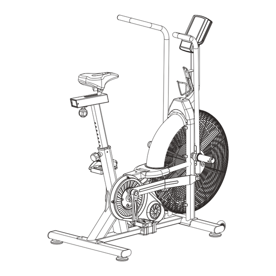
- Page 1 HIT00816 Hit Fitness HIIT Air Bike USER MANUAL...
- Page 2 TABLE OF CONTENTS Section Page Code Section Number Table of Contents Safety Information Before You Begin Section Page Code Section Number Exploded View & Hardware List 7-11 Assembly Instructions 12-19 Monitor Instruction Manual...
-
Page 3: Safety Information
SAFETY INFORMATION GENERAL SAFETY GUIDELINES FOR FITNESS PRODUCTS ・ Always read and understand the user manual equipment before assembling or operating any fitness equipment. Consult with a physician before starting any exercise program, especially if you have ・ pre-existing health conditions. ・... -
Page 4: Before You Begin
BEFORE YOU BEGIN CHOOSING THE RIGHT LOCATION Selecting the right location for your treadmill is crucial for safety and optimal performance. Consider the following when choosing a loc ation: ・ Stable Surface: Place the Air bike on a flat, stable surface to prevent wobbling or tilting during ... -
Page 5: Exploded View
EXPLODED VIEW... -
Page 6: Hardware List
HARDWARE LIST... - Page 7 HARDWARE LIST...
- Page 8 ASSEMBLY INSTRUCTIONS UNPACKIN AIR BIKE ・ Position the Box: Place the box in the location where you intend to use the Air bike. This will make the setup process smoother. ・ Open the Box: Carefully cut the tape and open the box. Avoid using sharp objects that might damage the product.
- Page 9 ASSEMBLY INSTRUCTIONS STEP 1 Attach the Front Stabilizer (15) to the Main Frame (16) using two sets of Flat Washers (5) and bolt 1 (7). Attach the Rear Stabilizer (4) to the Main Frame (16) using two sets of Flat Washers (5) ,DOMED NUT(6)and b olt 1 (3)
- Page 10 ASSEMBLY INSTRUCTIONS STEP 2 Insert the cushion adjustment tube assembly (10) into the bushing on the main frame assembly (16) and adjust to tighten the elastic latch (9). Lock (13) to the cushion slide assembly (12) by loosening the lock nut on the seat pad (13), adjust to the proper position and tighten the ball knob (68).
- Page 11 ASSEMBLY INSTRUCTIONS STEP 3 The left hand assembly (18), the right wrench assembly (21) and the outer tooth type gasket (92) are fixed to the main frame assembly (16) in accordance with the graphic method,the inner six angle flat head screws (78), flat washer (5), Spring washer(95),the lock nut (79) drive assembly connected then, locking;...
- Page 12 ASSEMBLY INSTRUCTIONS STEP 4 The Pedals (p1 L & p1 R) are marked "L" and "R" - Left and Right. Connect them to their appropriate crank arms. The right crank arm is on the right- hand side of the cycle as you sit on it. Note that the Right pedal should be threaded on clockwise and the Left pedal counterclockwise .
- Page 13 Monitor Instruction Manual...
- Page 14 Monitor Instruction Manual...
- Page 15 Monitor Instruction Manual...
- Page 16 Monitor Instruction Manual...
- Page 17 Monitor Instruction Manual...
- Page 18 Monitor Instruction Manual...
- Page 19 Monitor Instruction Manual...
Need help?
Do you have a question about the HIIT and is the answer not in the manual?
Questions and answers