
Related Manuals for AZ-Delivery DS1302


Summary of Contents for AZ-Delivery DS1302
- Page 1 Welcome! Thank you for purchasing our AZ-Delivery DS1302 Real-time Clock Module. On the following pages, you will be introduced to how to use and set-up this handy device. Have fun!
- Page 2 Areas of application Education and teaching: Use in schools, universities and training institutions to teach the basics of electronics, programming and embedded systems. Research and development: Use in research and development projects to create prototypes and experiments in the fields of electronics and computer science. Prototype development: Use in the development and testing of new electronic circuits and devices.
- Page 3 consult a doctor. Caution: Keep the product out of the reach of children and pets to avoid accidental contact and swallowing of small parts. Note: Store the product in a safe, closed container when not in use. Attention: Avoid contact of the product with food and drinks.
- Page 4 Table of Contents Introduction....................3 Specifications....................4 The pinout.....................5 How to set-up Arduino IDE................6 How to set-up the Raspberry Pi and Python..........10 Connecting the module with Atmega328p...........11 Library for Arduino IDE................12 Sketch example..................13 Connecting the module with Raspberry Pi..........22 Libraries and tools for Python..............23 Python script....................24 - 2 -...
- Page 5 Introduction The DS1302 Real-time Clock module is used as a time synchronization device in applications where precise timings are essential. The module is used in digital clocks, computer motherboards, digital cameras, embedded systems, etc. The module contains a real-time clock and 31B of RAM and provides clock and calendar functions.
- Page 6 When using a crystal with the specified characteristics, the startup time is usually less than one second. The DS1302 module can also use the external oscillatror, but this is not covered in this eBook.
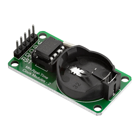
- Page 7 The pinout The DS1302 Real-time Clock module has five pins. The pinout is shown on the following image: - 5 -...
- Page 8 How to set-up Arduino IDE If the Arduino IDE is not installed, follow the link and download the installation file for the operating system of choice. For Windows users, double click on the downloaded .exe file and follow the instructions in the installation window. - 6 -...
- Page 9 For Linux users, download a file with the extension .tar.xz, which has to be extracted. When it is extracted, go to the extracted directory and open the terminal in that directory. Two .sh scripts have to be executed, the first called arduino-linux-setup.sh and the second called install.sh.
- Page 10 Almost all operating systems come with a text editor preinstalled (for example, Windows comes with Notepad, Linux Ubuntu comes with Gedit, Linux Raspbian comes with Leafpad, etc.). All of these text editors are perfectly fine for the purpose of the eBook. Next thing is to check if your PC can detect an Atmega328p board.
- Page 11 If the Arduino IDE is used on Windows, port names are as follows: For Linux users, for example, port name is /dev/ttyUSBx, where x represents integer number between 0 and 9. - 9 -...
- Page 12 How to set-up the Raspberry Pi and Python For the Raspberry Pi, first the operating system has to be installed, then everything has to be set-up so that it can be used in the Headless mode. The Headless mode enables remote connection to the Raspberry Pi, without the need for a PC screen Monitor, mouse or keyboard.
- Page 13 Connecting the module with Atmega328p Connect the module with the Atmega328p as shown on the following connection diagram: RTC pin Mc pin Wire color Red wire Black wire Blue wire Purple wire Green wire - 11 -...
- Page 14 Library for Arduino IDE To use the module with Atmega328p, it is recommended to download an external library. The library that is used in this eBook is called the RTC by Makuna. To download it, open Arduino IDE and go to: Tools >...
- Page 15 Sketch example #include <ThreeWire.h> #include <RtcDS1302.h> ThreeWire myWire(3, 4, 2); // DAT/IO, CLK/SCLK, RST/CE RtcDS1302<ThreeWire> Rtc(myWire); void setup Rtc.Begin(); Serial.begin(9600); //Uncomment to write current PC time to the RTC RtcDateTime cdt = RtcDateTime(__DATE__, __TIME__); //Uncomment to enter manualy date and time to the RTC //RtcDateTime cdt = RtcDateTime("Jan 14 2015", "09:55:20");...
- Page 16 void printDateTime(const RtcDateTime& dt) { //Day of the week Serial.print("Day of the week: "); (dt.DayOfWeek() == 1) { Serial.println("Monday"); else if (dt.DayOfWeek() == 2) { Serial.println("Tuesday"); else if (dt.DayOfWeek() == 3) { Serial.println("Wednesday"); else if (dt.DayOfWeek() == 4) { Serial.println("Thursday"); else if (dt.DayOfWeek() == 5) { Serial.println("Friday");...
- Page 17 //one tab Serial.print("/"); (dt.Month() < 10) { Serial.print("0"); Serial.print(dt.Month()); else Serial.print(dt.Month()); Serial.print("/"); Serial.println(dt.Year()); //Current Time Serial.print("Current Time: "); (dt.Hour() < 10) { Serial.print("0"); Serial.print(dt.Hour()); else Serial.print(dt.Hour()); Serial.print(":"); (dt.Minute() < 10) { Serial.print("0"); Serial.print(dt.Minute()); else Serial.print(dt.Minute()); - 15 -...
- Page 18 //one tab Serial.print(":"); (dt.Second() < 10) { Serial.print("0"); Serial.print(dt.Second()); Serial.println(); else Serial.print(dt.Second()); Serial.println(); - 16 -...
- Page 19 Upload the sketch to the Atmega328p and run the Serial Monitor (Tools > Serial Monitor). The result should look like as on the following image: - 17 -...
- Page 20 At the beginning of the sketch two libraries called ThreeWire and RtcDS1302 are imported. These libraries contain functions that are used for communication between the module and Atmega328p. The object myWire which represents the communication interface is created with the following line of code: ThreeWire myWire(4, 5, 2); where numbers 4, 5, and 2 represent digital pins on the Atmega328p through which the module is connected.
- Page 21 To set the current system date and time into the module, the following line of code is used: RtcDateTime cdt = RtcDateTime(__DATE__, __TIME__); With this line of code, the object called cdt is created, where __DATE__ __TIME__ arguments are used. The values of these arguments represent the current system date and time data.
- Page 22 The printDateTime() function has one argument and returns no value. The argument type is RtcDateTime which represents date and time data from the RTC. In the header of the function is the following: const RtcDateTime& dt where dt is the name of the parameter (argument); & means that the data is passed to the function by reference (what this means is not in the scope of this eBook);...
- Page 23 All other numeric values from data read from the RTC module are displayed with leading zero (for example adding zero to seconds), the following lines of code are used: if (dt.Second() < 10) { Serial.print("0"); } else { Serial.print(dt.Second()); - 21 -...
- Page 24 Connecting the module with Raspberry Pi Connect the module with the Raspberry Pi as shown on the following connection diagram: RTC pin Raspberry Pi pin Physical pin Wire color Red wire Black wire GPIO17 Green wire GPIO27 Purple wire GPIO22 Blue wire - 22 -...
- Page 25 Libraries and tools for Python To use the module with the Raspberry Pi, it is recommended to download an external library. In order to download an external library used in this eBook, the git app and rpi.gpio library should be installed. To do so, open the terminal and run the following commands, one by one: sudo apt-get update sudo apt-get upgrade...
- Page 26 '%d/%m/%Y %H:%M:%S' pyRPiRTC.DS1302(clk_pin=11, data_pin=13, ce_pin=15) set_date_time(time, f=my_format): global datetime.strptime(time, f) rtc.write_datetime(dt) print('Press CTRL + C to end the script!') try: # set_date_time('01/01/2020 09:13:55') # uncomment this to set date/time while True: rtc.read_datetime()
- Page 27 Save the script by the name ds1302.py. To run the script, open the terminal in the directory where the script is saved and run the following command: python3 ds1302.py The result should look like as on the following image: To stop the script press ‘CTRL + C’ on the keyboard.
- Page 28 Slashes “/” and colons “:” are used as separators. After this, the object called rtc is created with the following line of code: rtc = pyRPiRTC.DS1302(clk_pin=11, data_pin=13, ce_pin=15) where 11, 13 and 15 are the names of the GPIO pins (BCM) on which pins of the module are connected.
- Page 29 The second argument is called f and it represents the date and time format used for datetime() function. This argument is optional and its value is set by default to the value stored in my_format variable. The second argument is optional as it can be seen in the following line of code: def set_date_time(time, f=my_format): global rtc dt = datetime.strptime(time, f)
- Page 30 Next, the data from cdt object is displayed in the terminal The output can be seen on the image of the script output. The first except block is used to catch the ValueError. This error happens if the data can not be read from the RTC module. When this error happens, the message: error with RTC chip, check wiring is displayed in the terminal.
- Page 31 If you are looking for the high quality microelectronics and accessories, AZ-Delivery Vertriebs GmbH is the right company to get them from. You will be provided with numerous application examples, full installation guides, eBooks, libraries and assistance from our technical experts.
Need help?
Do you have a question about the DS1302 and is the answer not in the manual?
Questions and answers