
Related Manuals for AZ-Delivery GY-271


Summary of Contents for AZ-Delivery GY-271
- Page 1 Welcome! Thank you for purchasing our AZ-Delivery GY-271 Compass Magnetic Module. On the following pages, you will be introduced to how to use and set- up this handy device. Have fun!
-
Page 2: Table Of Contents
Table of Contents Introduction....................3 Specifications....................5 Operation modes...................7 The pinout....................10 How to set-up Arduino IDE................11 How to set-up the Raspberry Pi and the Python.........15 Connecting the sensor with Uno..............16 Library for Arduino IDE................17 Sketch example..................18 Connecting the sensor with Raspberry Pi...........23 Enabling I2C interface................24 Libraries and tools for Python..............25 Python script....................27... -
Page 3: Introduction
Introduction The heart of a GY-271 module is the QMC5883L chip. The module is targeted for high precision applications such as compassing, navigation and gaming in drone, robotic, mobile and personal hand-held devices. The chip is actually a multi-chip, magnetoresistive sensor circuit which consists of tri- axial sensors and application specific integrated circuits (ASIC) to measure magnetic fields. - Page 4 This device is connected to a serial interface, but as a slave device under the control of a master device, such as the microcontroller. Control of this device is carried out via the I2C interface. This device supports standard and fast speed modes, 100kHz and 400kHz, respectively. External pull-up resistors are required to support all these modes.
-
Page 5: Specifications
Specifications » Operating voltage range: from 3.3V to 5V DC » Low Power Consumption: 75µA » Communication interface: I2C (standard and fast modes) » Default I2C address: 0x0D » Compass accuracy: 1° to 2° » Operating temperature range: from -40°C to +85°C »... - Page 6 When the device is powered on, all registers are reset by POR, then the device transits to the stand-by mode and waits for further commands. The QMC5883L chip also has a built-in temperature sensor that can provide temperature reading for other applications. Temperature compensation of the measured magnetic data is enabled by default at the factory.
-
Page 7: Operation Modes
Operation modes Continuous-Measurement Mode During continuous-measurement mode, magnetic sensor continuously makes measurements and places measured data in the data output registers. In the continuous-measurement mode, the magnetic sensor data is automatically compensated for offset and temperature effects. The gains are calibrated in the factory. Normal Read Sequence Normal read complete magnetometer data read-out can be done as follows: »... - Page 8 During the measurement, it is possible to read the data register which keeps the previously measured data. Therefore, no interrupt (DRDY bit) will be set if data reading occurs in the middle of measurement. If N-th data is skipped, the current data is flushed by the next coming data. In this case, interrupt (DRDY bit) keeps high until data is read.
- Page 9 Stand-by Mode The stand-by mode is a default state of the chip, upon Power On Reset (POR) or soft reset. Оnly a few function blocks are activated in this mode, which keeps power consumption as low as possible. In this state, register values are held ON by an ultra-low power.
-
Page 10: The Pinout
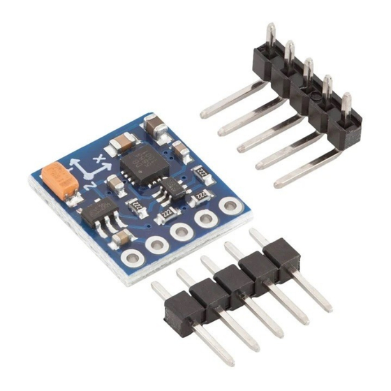
The pinout The GY-271 compass magnetic module has five pins. The pinout is shown on the following image: The power supply and logic pins work on voltages in a range from 3.3V up to 5V. The DRDY pin is used to indicate that measurement is finished. You can use it as an interrupt, as a signal to start reading data from the sensor. -
Page 11: How To Set-Up Arduino Ide
How to set-up Arduino IDE If the Arduino IDE is not installed, follow the link: https://www.arduino.cc/en/Main/Software and download theinstallation file for the operating system of choice. For Windows users, double click on the downloaded .exe file and follow the instructions in the installation window. - 11 -... - Page 12 For Linux users, download a file with the extension .tar.xz, which has to be extracted. When it is extracted, go to the extracted directory and open the terminal in that directory. Two .sh scripts have to be executed, the first called arduino-linux-setup.sh and the second called install.sh.
- Page 13 Almost all operating systems come with a text editor preinstalled (for example, Windows comes with Notepad, Linux Ubuntu comes with Gedit, Linux Raspbian comes with Leafpad, etc.). All of these text editors are perfectly fine for the purpose of the eBook. Next thing is to check if your PC can detect an Arduino board.
- Page 14 If the Arduino IDE is used on Windows, port names are as follows: For Linux users, for example, port name is /dev/ttyUSBx, where x represents integer number between 0 and 9. - 14 -...
-
Page 15: How To Set-Up The Raspberry Pi And The Python
Raspberry Pi itself, power supply and internet connection. All of this is explained in detail in the free eBook: Raspberry Pi Quick Startup Guide which can be found on the following link: https://www.az-delivery.de/products/raspberry-pi-kostenfreies-e-book?ls=en The Raspbian operating system comes with Python preinstalled. - 15 -... -
Page 16: Connecting The Sensor With Uno
Connecting the sensor with Uno Connect the GY-271 compass magnetic module with the Uno as shown on the following connection diagram: Sensor pin > Uno pin > 5V Red wire > GND Black wire > A5 [SCL] Blue wire > A4... -
Page 17: Library For Arduino Ide
Library for Arduino IDE To use the sensor with a Uno, it is recommended to download an external library for it. The library that is used in this eBook is called the QMC5883L. To download and install it, open Arduino IDE and go to: Tools >... -
Page 18: Sketch Example
Sketch example #include <QMC5883LCompass.h> QMC5883LCompass compass; void setup() { Serial.begin(9600); compass.init(); void loop() { compass.read(); // Read compass values byte a = compass.getAzimuth(); // Return Azimuth reading Serial.print("Azimuth: "); Serial.println(a); byte d = compass.getBearing(a); // Output is a value from 0 - 15 // based on the direction of the bearing / azimuth Serial.print("Direction: ");... - Page 19 Upload the sketch to the Uno and open Serial Monitor (Tools > Serial Monitor). The result should look like the output on the following image: To get similar values, rotate the compass board around one of its axis. - 19 -...
- Page 20 The sketch starts with importing a library QMC5883LCompass. Next, an object called compass is created, which represents the module itself. This object is used to initialize and read the data from the modul. In the setup() function the serial communication is started with a baud rate of 9600bps.
- Page 21 Then, the Azimuth values are converted to direction numbers and displayed in the Serial Monitor. There are eight directions on the compass: » North » North-East » East » South-East » South » South-West » West » North-West Which can be seen on the compass circle, there are 16 different areas, like on the following image: - 21 -...
- Page 22 The function called getBearing() has one argument and returns a value. The argument is an integer number, which represents the Azimuth value. The return value is also an integer number, in the range from 0 to 15, which represents one of directions number from the compass circle image. After this, the direction numbers are converted to direction letters with the following lines of code: char compassLetters[3];...
-
Page 23: Connecting The Sensor With Raspberry Pi
Connecting the sensor with Raspberry Pi Connect the GY-271 compass magnetic module with the Raspberry Pi as shown on the following connection diagram: Sensor pin > Raspberry Pi pin > 3V3 [pin 1] Red wire > GND [pin 9] Black wire >... -
Page 24: Enabling I2C Interface
Enabling the I2C interface In order to use the sensor with Raspberry Pi, the I2C interface on the Raspberry Pi has to be enabled. To do so, go to: Application Menu > Preferences > Raspberry Pi Configuration When a new window opens, find the Interfaces tab. Then enable I2C radio button and click OK, like on the following image: - 24 -... -
Page 25: Libraries And Tools For Python
Libraries and tools for Python In order to use the module with the Raspberry Pi it is recommended to download and install an external library for it. The library that is used in this eBook is called gy271compass. Before it is used, several libraries and tools have to be installed. - Page 26 If the I2C interface of the Raspberry Pi is not enabled, when the previous command is executed, the following error will be raised: To download the external library, save the script gy271compass.py from the following link: https://github.com/Slaveche90/gy271compass Or use the git to clone the repository, by running the following command in the terminal: git clone https://github.com/Slaveche90/gy271compass This command will create a directory called gy271compass.
-
Page 27: Python Script
Python script import gy271compass GY271 from time import sleep sensor GY271.compass(address=0x0d) print('[Press CTRL + C to end the script!]') try: while True: angle sensor.get_bearing() temp sensor.read_temp() print('Heading Angle = {}°'.format(angle)) print('Temperature = {:.1f}°C'.format(temp)) sleep(1) except KeyboardInterrupt: print('\nScript end!') - 27 -... - Page 28 Save the script by the name gy271.py in the same directory where you saved the gy271compass script. To run the gy271.py script open terminal in the directory where you saved the script and run the following command: python3 gy271.py The result should look like the output in the following image: To stop the script press CTRL + C on the keyboard.
- Page 29 The script starts by importing external class library gy271compass and the time library. Next, the object called compass is created using the following line of code: sensor = GY271.compass(address=0x0d) where 0x0d is the I2C address of the module. Then, the try-except block of code is created. In the try block of code an indefinite loop (while True:) is created.
- Page 30 The module has several options that can be set at the sensor object creation. You can pass the following arguments to the compass() constructor: - the I2C address of the module address=0x0d - Continuous or stand-by mode: mode=MODE_CONT MODE_CONT or MODE_STBY - Output Data Rate, with values: odr=ODR_10Hz ODR_10Hz,...
-
Page 31: Calculating Declination
Calculating declination To calculate the magnetic declination value, go to the following link: https://www.magnetic-declination.com/YUGOSLAVIA/NEOPLANTA/2970848.html and find your location. Next, click with your PC mouse on the location and pop up will be displayed. Copy the following data: And use the angle minutes to decimal converter, for example: https://www.rapidtables.com/convert/number/degrees-minutes-seconds-to-degrees.html to get the floating point value of the angle. - Page 32 If you are looking for the high quality products for Arduino and Raspberry Pi, AZ-Delivery Vertriebs GmbH is the right company to get them from. You will be provided with numerous application examples, full installation guides, eBooks, libraries and assistance from our technical experts.
Need help?
Do you have a question about the GY-271 and is the answer not in the manual?
Questions and answers