
Related Manuals for AZ-Delivery TP5400


Summary of Contents for AZ-Delivery TP5400
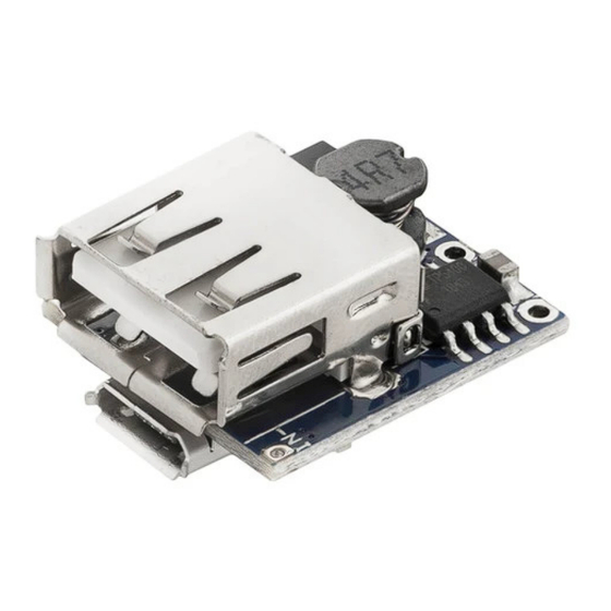
- Page 1 Welcome! Thank you for purchasing our AZ-Delivery TP5400 Power Bank Charger Modul. On the following pages, you will be introduced to how to use and set-up this handy device. Have fun!
- Page 2 Areas of application The module is specifically designed for applications in the areas of prototyping, education, research and teaching. It is used to develop and test chargers and to provide practical knowledge of lithium polymer batteries and electrical circuits. Required knowledge and skills Using the module requires in-depth knowledge of electrical engineering, especially in dealing with Li-Po batteries and char- gers.
- Page 3 charge damaged or swollen Li-Po batteries and never leave batteries unattended while charging.
-
Page 4: Table Of Contents
Table of Contents Introduction....................3 Specifications....................4 Working principle..................5 The pinout.....................6 The schematic....................7 Connection example..................8... -
Page 5: Introduction
It is designed to supply microcontrollers such as Atmega328p, Raspberry Pi and others. It is based around a TP5400 chip. It has the capability to charge Li-Po and LiIon batteries on one hand and capability of the boost converter that provides 5V from the lower battery voltage on the other hand. -
Page 6: Specifications
- 125 Dimensions 22x18x11mm (0.8x0.7x0.4in) The TP5400 charger module has two on-board (Red, Green) LEDs. The red LED indicates the charging process. As soon as the battery is charged, the green LED is activated. WARNING: Reversing polarity on battery pins will damage the module! -
Page 7: Working Principle
When the VOUT terminal is connected to the load, TP5400 can provide a 5V stabilized voltage source with a drive capacity of 1A. When the VCC pin voltage rises to a certain threshold level with the battery connected to the charger, the output charging cycle begins. -
Page 8: The Pinout
The pinout The module has four pins, one female USB connector and one µUSB connector. The pinout is shown on the following image:... -
Page 9: The Schematic
The schematic The following schematic is a basic circuit representation that is designed around TP5400 chip:... -
Page 10: Connection Example
Connection example The following image is an example of how to connect the module with the battery:... - Page 11 Internet. If you are looking for the high quality microelectronics and accessories, AZ-Delivery Vertriebs GmbH is the right company to get them from. You will be provided with numerous application examples, full installation guides, eBooks, libraries and assistance from our technical experts.
Need help?
Do you have a question about the TP5400 and is the answer not in the manual?
Questions and answers