Advertisement
Quick Links
Advertisement

Related Manuals for Eurovema EUROFLEX JUNIOR


Summary of Contents for Eurovema EUROFLEX JUNIOR
- Page 1 User Manual, English Work chair JUNIOR Rev: 01/07/2024...
- Page 2 Contents INTRODUCTION ............................4 CONTACT DETAILS ........................... 4 USER INFORMATION ..........................4 SERVICE AND WARRANTY........................4 ASSEMBLY UPON DELIVERY ........................5 SAFETY RULES ............................5 SYMBOL KEY ............................6 WARNING ..............................7 REPORTING OF ACCIDENTS AND INCIDENTS ................... 8 CLEANING ..............................8 STORAGE..............................
- Page 3 LEVER BRAKE AND FOOT BRAKE ......................31 CHARGING - GENERAL ........................... 33 CHARGER INDICATORS .......................... 34 TECHNICAL DATA - CHARGER ........................ 34 TECHNICAL DATA - ELECTRONICS ......................35 TECHNICAL DATA - BATTERY ......................... 35 REPLACING THE BATTERY ........................35 TECHNICAL DATA - SEAT SYSTEM ......................36 TECHNICAL DATA - CHASSIS ........................
- Page 4 The chair has many options for adjustment, meaning that it can be adapted to every need. Read the User Manual carefully so you can make use of all the options provided by your chair. Eurovema reserves the right to make changes to this manual and its contents.
- Page 5 • safety. Contact the service organisation immediately. • Service and maintenance must only be carried out by a Eurovema authorised technician. Only original parts from Eurovema may be used. • The chair must not be equipped with any accessories or components other than those •...
- Page 6 SYMBOL KEY Warning Read User Manual Warning, risk of crushing Seat tilt Do not iron Adjustable back tilt Do not use dry cleaning solvents stronger than tetrachloroethylene Back height Do not use bleach Seat depth Do not tumble dry Armrest height Operation button, electric function Machine wash 60°...
- Page 7 Aid Centre or Eurovema Mobility AB for advice. Modifications to the product will invali- date the CE mark and Eurovema will no longer accept any liability. Modifications carried out by an authorised technician that have been agreed with Eurovema may allow the CE mark to remain valid.
- Page 8 The awarding of a CE mark shows that the product has undergone a series of risk analyses and tests, with steps taken to minimise any risks identified as far as possible. If, despite everything, accidents or incidents occur, such events must be reported to Eurovema Mobility AB and the relevant national authority.
- Page 9 LABEL The label on the product contains important information. 1) Product name 2) Item number 3) Serial number UDI-PI 4) Barcode 5) Max user weight 6) Medical device 7) CE marking 8) Read the manual before use 9) Manufacturing date 10) Manufacturer’s name SECONDARY LABEL 1) Applied part type B...
- Page 10 OVERVIEW - MARKING Loose covers can be machine washed. Crush risks are reported in connection with instructions for each function that may constitute a risk of crushing. Marking appears on the chair where there is a risk of crushing.
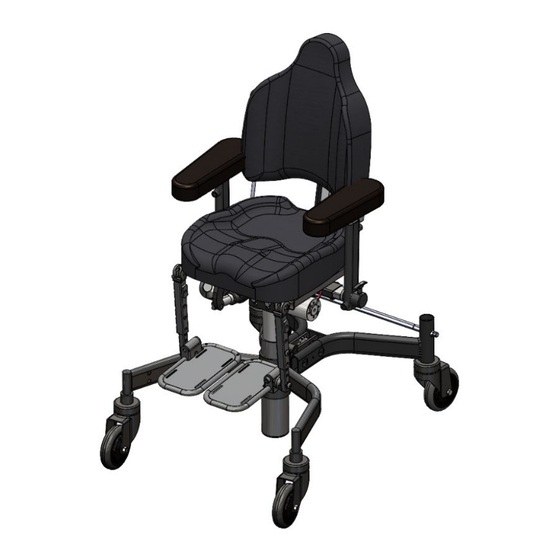
- Page 11 OVERVIEW - SEAT UNIT 1) Seat 2) Back support 3) Armrest 4) Chassis 5) Seat lift 6) Leg support Alternative seat systems and leg supports are available.
- Page 12 CHASSIS OVERVIEW 1) Front wheel 2) Braked wheel 3) Parking brake lever 4) Foot brake 5) Chassis, Junior 52 6) Brake rod...
- Page 13 BACK SUPPORT - HEIGHT The back support is height adjustable using a screw and a lever. 1) Loosen the lever a ½ turn by turning it anticlockwise. 2) Set desired height. 3) Lock the back by turning the lever clockwise a ½ turn. 4) To adjust the height further, loosen the adjustment screw a few turns.
- Page 14 BACK SUPPORT - MANUAL TILT The back tilt and back cushion are individually adjustable. Adjustable back tilt 1) Undo the safety screw and lever to tilt the entire back mechanism backwards or forwards. 2) Set desired back angle. 3) Lock safety screw and lever Back cushion 4) Loosen the lever by turning it anticlockwise a ½...
- Page 15 BACK TILT - ELECTRONIC The back mechanism tilt is electronically adjustable. 1) Tilt back by moving the rocker power switch upwards. 2) Tilt forwards by moving the rocker power switch downwards. Do not adjust the back tilt in the immediate vicinity of another person as there is a risk of crushing.
- Page 16 BACK SUPPORT - SEAT DEPTH Seat depth can be adjusted using the back support. Set the desired seat depth by moving the back support backwards or forwards. Fine tuning of the seat depth can also be done using the back tilt. 1) Loosen the locking screw/knob under the seat on the rear edge.
- Page 17 SEAT TILT - MANUAL The seat angle is adjustable in several ways. Manual tilt mechanisms are: Turnbuckle (1) and Crank (2). 1) The turnbuckle is adjusted using a 17mm box wrench. 2) Crank tilt is adjusted by turning the wheel. Turn clockwise to tilt forwards. Turn anticlockwise to tilt back.
- Page 18 SEAT HEIGHT - GAS AND ELECTRIC 3) Gas-controlled seat tilt is regulated using the control located under the armrest cushion. To adjust the seat angle, press the control upwards towards the armrest cushion and release once the desired angle has been reached. The control can be moved from right to left side. 4) Electric seat tilt is controlled using either the rocker switch located under the armrest or the hand control.
- Page 19 ARMREST - FIXED 1) To adjust the height, loosen the wheel 1) a few turns anticlockwise and set to the desired height. 2) Tighten the wheel clockwise. 3) To adjust width, loosen the lever 2) a ½ turn anticlockwise and adjust to the desired width.
- Page 20 ARMREST - RETRACTABLE The armrest can be folded backwards by pulling the spring-loaded control 1) upwards and pushing the armrest backwards at the same time. 1) The height of the armrest is adjusted by the lever or screw 2) being loosened a ½ turn anticlockwise.
- Page 21 SEAT HEIGHT - MANUAL 1) Raising and lowering of the seat is done by moving the lever (1) down. The seat is lowered using the user's body weight. The lever must be held in the down position. 2) Release the lever once the desired seat height has been reached. Take care when lowering the seat to ensure that nothing or no-one gets crushed when raising the seat.
- Page 22 SEAT HEIGHT - ELECTRIC 1) To raise or lower the seat, move the rocker switch upward to raise the seat and downwards to lower the seat. Hand control are available as an optional extra. Take care when lowering the seat to ensure that nothing or no-one gets crushed when raising the seat.
- Page 23 SEAT ROTATION Seat rotation is available as an optional extra. The seat can be rotated 90° in both directions, with a centre point of 45 degrees. Apply the chair brake. Move the lever upwards whilst turning the seat. Release the lever once the desire position has been reached.
- Page 24 FOOTPLATE - HEIGHT 1) Loosen the safety screw (1) a few turns using Allen key no. 4. 2) Loosen the screw (2) a few turns and adjust to the desired height using Allen key no. 5. 3) Tighten the screw (2) and the safety screw (1). Do not stand on the footplate.
- Page 25 LEG SUPPORT, FULL FOOTPLATE - TILT 1) Loosen the screw (1) a few turns using Allen key no. 5 2) Adjust to the desired angle. 3) Tighten the screw. Do not stand on the footplate, the chair will tip forwards...
- Page 26 FOOTPLATE - TILT The footplate can be adjusted horizontally. To tilt it downwards, turn the screw anticlockwise using Allen key no. 4 until the desired angle is reached. To tilt upwards. turn the screw clockwise. Do not stand on the footplate, the chair will tip forwards...
- Page 27 BIFURCATED FOOTREST - HEIGHT 1) Completely undo the screw (1) and adjust the footplate to the desired height using Allen key no. 5. 2) Once the desired height has been reached, refit the screw and tighten it. Do not stand on the footplate, the chair will tip forwards...
- Page 28 BIFURCATED LEG SUPPORTS - TILT The leg supports are angle adjustable. Loosen the screw a few turns using Allen key no. 5. Adjust to the desired position and tighten the screw. Do not stand on the footplate, the chair will tip forwards...
- Page 29 BIFURCATED FOOTPLATES - ANGLE The angle of the footplate can be adjusted to a position that is comfortable for the user. Undo the screw (1) using Allen key no. 5 a few turns and adjust the angle. Tighten the screw once the desired angle has been reached.
- Page 30 FOOT RING The foot ring can be folded backwards to facilitate getting in and out of the chair. Fold the foot ring away before getting out of the chair in order to reduce the likelihood of a fall.
- Page 31 LEVER BRAKE AND FOOT BRAKE Lever brake Brake the chair by moving the brake lever forwards. Release the brake by moving the lever backwards. Foot brake Brake the chair by stepping on the front part of the pedal. Release the brake by stepping on the rear part of the pedal.
- Page 32 The brake lever is angle adjustable and can be moved from one side to the other, Angle adjustment. Undo the screw a few turns to release the gear lock. NB Do not completely undo the lever. Adjust the angle of the lever to the desired position and firmly tighten the screw.
- Page 33 CHARGING - GENERAL To ensure full battery performance for as long as possible, it is important that the battery is charged regularly. In an average use scenario, charging the battery every other day is a good guideline. If possible, charge the battery during the day. Seat functions cannot be used whilst the battery is charging.
- Page 34 CHARGER INDICATORS Charging at maximum current Top charging, constant voltage Flashes yellow Charge complete, Maintenance charging Battery not connected Flashes green Fault codes 2 red flashes, battery connected but wrong polarity 3 red flashes, charger output shorted 4 red flashes, battery voltage too low 5 red flashes, charging time too long 6 red flashes, damaged battery LED not illuminated, battery voltage too high...
- Page 35 Repairs and other procedures on the battery may only be carried out with the approval of Eurovema. The battery box contains no user serviceable parts and must not be opened. Only Eurovema-approved batteries may be used.
- Page 36 TECHNICAL DATA - SEAT SYSTEM Data Facts Seat (width x depth)* 29x32, 32x36, 36x40,36x45, 40x40, 40x45 **32x36, 36x40, 40x40, 40x46 Seat width between armrests 27-52cm Seat depth 32-45cm Seat height, gas (height to underside of seat)* 37.5–47, 41–56, 48-68cm Seat height, electric (height to underside of seat) 41–57, 45-70cm Seat tilt, electrical and gas -20 to 12°...
- Page 37 Instructions section. Detailed diagrams can also be found on the website in the Exploded Diagrams www.eurovema.se section. Point your browser to Private individuals should contact Eurovema for more information. Eurovema will assume responsibility for destruction. Disassembled components are to be sorted in accordance with the table below.
Need help?
Do you have a question about the EUROFLEX JUNIOR and is the answer not in the manual?
Questions and answers